

使用RealSense D455的空间识别操作myCobot
电子说
描述
1. 简介
先进技术部门正在研究多模态强化学习,包括相机图像和触觉传感器。除其他外,要实现所谓的Sim2Real,其中模拟器中的强化学习结果也在实际机器上运行,必须协作操作真实机器的机械臂和相机。因此,在这种情况下,我们使用ROS测试了链接的6轴机械臂myCobot(由大象机器人制造)和深度摄像头RealSense D455(由英特尔制造),流程和结果将在下面详细描述。
操作环境:
PC:Ubuntu 20.04, ROS Noetic, Python 3.8.10
机械臂:myCobot280 M5Stack
深度摄像头:实感D455
这篇博客描述了如何创建和运行一个简单的程序,但我假设 ROS 和 Python 环境已经设置好了。
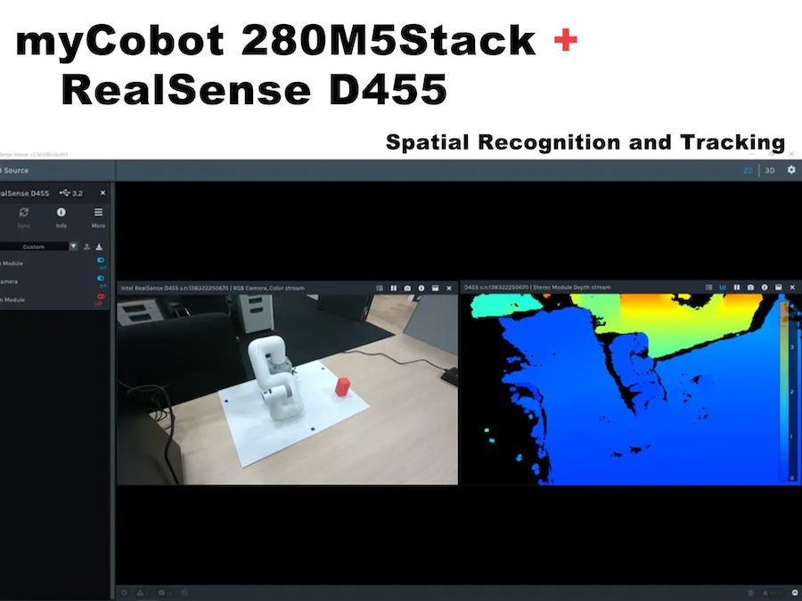
2. 我的协作机器人基础知识
首先,准备myCobot,但我有点困惑,因为由于固件更新等原因,某些部件在使用中发生了变化。这项工作是在 2021 年 3 月左右完成的,当时 myStudio 版本是 1.3.<>。我认为不会有任何重大变化,但如果您看到不同之处,请参阅官方说明。
运行myCobot需要以下三个准备工作。
● 更新固件(基本,原子)
● 机械臂关节校准
● 机械臂与PC机之间的串行通信
更新固件
myCobot 280 M5在底座上有一个M5Stack Basic,在机械臂的末端有一个ATOM(Basic,ATOM),用于将固件写入这两个模块。
首先,使用 USB 连接到 PC,并使用 chmod 允许读取和写入设备。此外,对于Windows或Mac上的USB串行通信,需要安装特殊的驱动程序。
$ sudo chmod 666 /dev/ttyUSB*
接下来,下载更新的固件应用程序-myStudio(在撰写本文时,最新版本是3.1.4,但仅适用于Windows,3.1.3可用于Linux)。
提取源代码并执行 AppImage 后,它将分别启动 Basic 和 ATOM。如图 1 和图 2 所示。
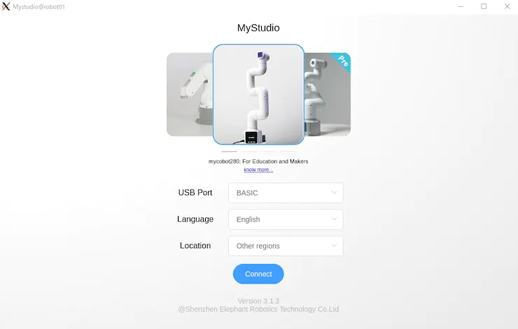
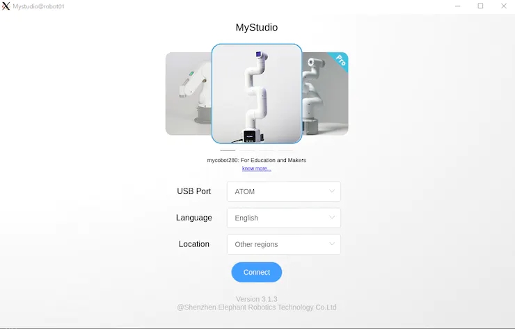
在myStudio 3.1.3中,将出现如图3和图4所示的屏幕,然后下载最新版本的Minirobot for Basic和AtomMain for ATOM,选择Flash,然后写入固件。使用Basic完成写入后,迷你机器人的输出将显示在面板上。(请注意,如果您不使用Basic和ATOM编写最新版本,则机器人手臂可能无法正常工作)。
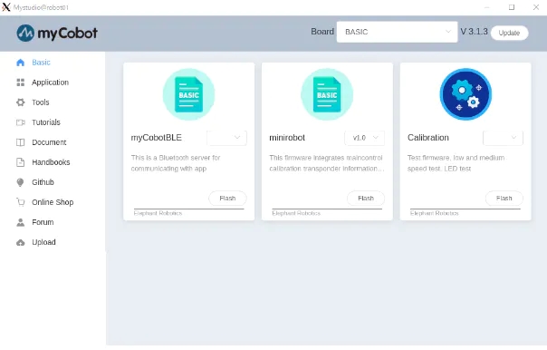
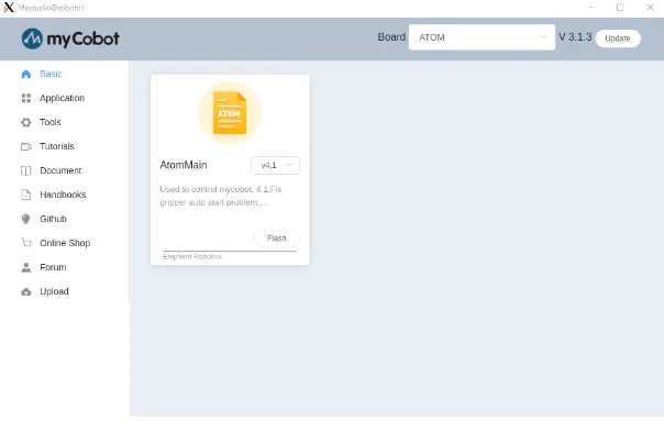
更新固件后,下一步是校准接头角度。
接头角度校准
首先,在“基本”面板中选择“校准”,然后按“确定”。
myCobot 的每个接头都有一个代表原点的凹口,如图 5 所示,因此凹口是手动相互对齐的。
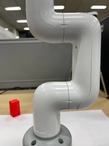
在此状态下,在“基本”面板中选择“校准伺服”,然后按“下一步”完成校准。运行测试伺服将允许电机围绕凹口稍微旋转以确认正确校准。
机械臂和PC之间的串行通信
最后,当您启动应答器时,您可以通过串行通信从PC操作myCobot。这很容易做到,只需在“基本”面板中选择应答器,然后按“确定”。然后显示屏将显示如图6所示,按基本按钮。
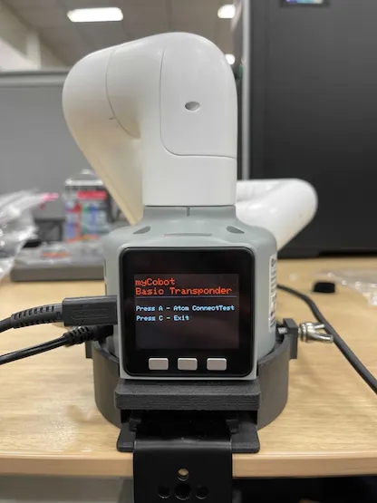
在“基本”面板的其他菜单中,“基本”中的“主控制”控制 ATOM,“信息”检查每个关节是否正确连接。当myCobot在PC上无法正常工作时,您可以检查myCobot本身是否存在问题。
3. 蟒蛇接口
准备完成后,我们可以在PC上操作myCobot。这次,我尝试了使用 pymycobot 从 python 脚本进行操作的方法,以及使用 mycobot_moveit 库从 ROS 操作 MoveIt 的方法 。
首先,安装pymycobot。
$ pip install pymycobot --upgrade
您也可以从 Github 下载安装源代码。
从源代码下载时,示例脚本包含在测试目录中。但是,它不会按原样工作,因此请小心。我做了下面的例子,而不是重写。
# mycobot_control_test.py#!/usr/bin/env pythonimport time from pymycobot.mycobot import MyCobotfrom pymycobot.genre import Angle, Coord if __name__ == "__main__":port = "/dev/ttyUSB0"mycobot = MyCobot(port, baudrate="115200", timeout=0.1, debug=False) #After the baud rate are the default values #Get the operation of the joint angleprint("get angles")print(" degrees: {}n".format(mycobot.get_angles()))time.sleep(0.5) print("get radians")print(" radians: {}n".format(mycobot.get_radians()))time.sleep(0.5) print("send angles: [0, 0, 0, 0, -90, 0]")mycobot.send_angles([0, 0, 0, 0, 0, 0], 80)time.sleep(1.5)mycobot.send_angles([0, 0, 0, 0, -90, 0], 80)print(" Is moving: {}n".format(mycobot.is_moving()))time.sleep(1.5) print("send radians: [0, 0, 0, 0, 1.57, 0]n")mycobot.send_radians([0, 0, 0, 0, 1.57, 0], 80)time.sleep(1.5) print("send angle to joint 4: -90n")mycobot.send_angle(Angle.J4.value, -90, 80)time.sleep(1.5) # Operations to get coordinatesprint("get coordination")print(" coordination {}n".format(mycobot.get_coords()))time.sleep(0.5) print("send coordination: [50, 50, 300, 0, 0, 0] → [50, 50, 300, 90, 90, 0]n")coord_list = [50, 50, 300, 0, 0, 0]mycobot.send_coords(coord_lis, 70, 0)time.sleep(3.0)coord_list = [50, 50, 300, 90, 90, 0]mycobot.send_coords(coord_lis ,70, 0)time.sleep(1.5) # Scenarios using grippers# print("open gripper")# mycobot.set_gripper_state(0,0)# time.sleep(1.0)# print("close gripper")# mycobot.set_gripper_state(1,80)# time.sleep(1.0) time.sleep(1.5)print("release all servos")mycobot.release_all_servos()
运行mycobot_control_test.py文件
$ python3 mycobot_control_test.py
在 mycobot 模块中创建 MyCobot 类的实例,并使用 getter 和 setter 来检查和更改状态。
创建实例
mycobot = MyCobot(port, baudrate="115200", timeout=0.1, debug=False)
设置四个参数。在波特率之后输入默认值。端口是 USB 串行通信端口。您可以通过在终端中运行ls / dev /来查看连接到PC的设备列表。在Linux中,如果没有其他用于串行通信的USB端口,它将是/ dev / ttyUSB0。我认为Mac和Windows是不同的,所以相应地检查。
关于吸气剂
get_angles ( ) 和 get_radians () 是获取关节角度(以度和弧度为单位)的函数。返回值是六个关节角度值的列表。
还有一个get_coords( )函数,它获取以底底中心为原点的坐标系*中手臂尖端的坐标。返回值是一个 6 维列表,其中包含尖端的 x、y、z 坐标 (mm) 和方向 rx、ry、rz(角度)。在没有 MoveIt 的情况下实现反向运动学真是太好了。
*坐标系:以“基本”面板为背面,每个正方向分别为 x:向前、y:向左和 z:向上。请注意,MoveIt 中的向量略有不同,稍后将对此进行介绍。
关于二传手
以度和弧度为单位发送关节角的函数是send_angles ( ) 和 send_radians ( ),并且具有两种类型的参数设置。
首先,在指定并发送所有 6 个关节时,第一个参数与 getter 相同,在列表类型中放入 6 个浮点值,第二个参数中输入关节运动的速度 *(int: 0 ~ 100)。
mycobot .send_angles ( [ 0 , 0 , 0 , 0 , 0 , 0 ] , 80 )
接下来,您取关节的角度并发送它。请将关节角度的代码放在第一个参数中,角度值放在第二个参数中,速度放在第三个参数中。
mycobot .send_angle ( Angle.J4.value , -90,80 )
也可以通过像getter这样的坐标来操作。在这种情况下,放置了 6 个元素的列表 [x, y, z, rx, ry, rz],第一个参数是协调的,第二个参数是速度,第三个参数是模式。模式有两种类型,0:角度和1:线性
mycobot .send_coords ( [ [ 80 , 50 , 300 , 0 , 90 , 0 ] , 70 , 0 )
由于源代码中没有详细说明速度单位,因此我认为您在必要时对其进行测量。
其他接口
一旦机械臂移动,电机将继续施加扭矩以试图保持当前状态,因此如果保持原样,电机将过载。因此,让我们在操作完成后使用函数release_all_servos(y)释放电机扭矩。
如果机器人手臂正在运行,并且您指示它执行另一个操作,则会发生错误,它将继续执行下一个操作。在示例脚本中,python内置函数time.sleep()用于等待每个动作完成,但您可以使用函数is_moving()来获取电机是否正在运行,以便您可以循环while等。(我认为这个函数是错误,并返回一个不断移动的状态。
还有一些其他 API 可用于打开和关闭电源、更改 LED 的颜色以及检查电机状态,但这次我省略了它们,因为目标是移动手臂。
4. 只读标准
接下来,在ROS中使用MoveIt来操纵myCobot。
大象机器人实现mycobot的动作它可以安装并可以安装
有一个MoveIt的志愿者实现,我决定使用它。安装是根据上面的 GitHub 自述文件编写的。
$ cd /src$ git clone https://github.com/Tiryoh/mycobot_ros$ git clone https://github.com/nisshan-x/mycobot_moveit$ rosdep update$ rosdep install -i –from-paths mycobot_moveit$ cd .$ catkin_make #Set up work area$ source devel/setup.bash
完成安装和设置工作区后
$ roslaunch mycobot_moveit mycobot_moveit_control.launch
MoveIt 和 Rviz GUI 将启动,如图 7 所示。通过拖放绿色球,计算出机器人手臂末端位置的姿势,然后按下左下角的计划和执行按钮,Rviz 与实际机器人一起移动。
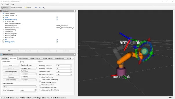
* 当模型和实际机器不能一起工作时
我不知道这是否是所有环境中都会发生的错误,并且模型和真实机器并不总是协同工作。这是电机旋转方向反转时发生的错误,所以有点棘手,但请将模型与真机进行比较,寻找相反方向的关节旋转。
确认有多少关节沿相反方向旋转后,重写描述机器人模型的 URDF 文件。
/ src / mycobot_moveit / urdf / mycobot_urdf_gazebo.urdf
定义的联合信息的说明如下。
mycobot_urdf_gazebo.urdf ~~ ~~
Arm1 ~ arm6_joint 相同的说明。旋转轴的方向设置为<轴xyz = “0 0 1”> ,并且设置1→-1反转关节在相反方向上的旋转。
在我的环境中,似乎除了第三个关节之外的所有关节都是反转的。我不知道这是因为机器人舵机的个体差异还是其他原因,如果您知道,请告诉我。
这就是它的全部内容,从myCobot设置到操作基础。
5. 现实D455基础知识
这次我用D455进行了测试,但基本上D400系列可以以相同的方式使用。只有D435i和D455内置了IMU传感器,但本文没有用到(因为误差累积的缺点比在固定状态下使用IMU的优点更明显)。除了带有红外立体摄像头的D400系列外,还有带有LiDAR的L515,但用途相同。另外,我认为新的性能最好,所以我会买D455。我认为最好在购买前咨询一下您想使用的环境,因为有一些零件(以前的型号基本上是向后兼容的,所以在价格和性能之间有一个权衡)。
查看器的软件安装和基本操作
安装库 librealsense 以运行实感。 没有这个,后面将描述的realsense_ros将无法工作。有一个关于如何在 Linux 上安装它的文档。如果需要,Windows 上的安装方法也位于同一文档库中。
# Server Public Key Registration$ sudo apt-key adv –keyserver keyserver.ubuntu.com –recv-key F6E65AC044F831AC80A06380C8B3A55A6F3EFCDE|| Adding a Repository$ sudo add-apt-repository “deb https://librealsense.intel.com/Debian/apt- repo $(lsb_release -cs) main” -u# install lib$ sudo apt install librealsense2-dkms librealsense2- utils# install dev$ sudo apt install librealsense2-dev librealsense2-dbg
安装完成后,在终端中运行实感查看器进行查看。如果它不起作用,请尝试拔下并插入实感 USB 连接并重新启动 PC。如果启动成功,将显示查看器,如图 8 所示。
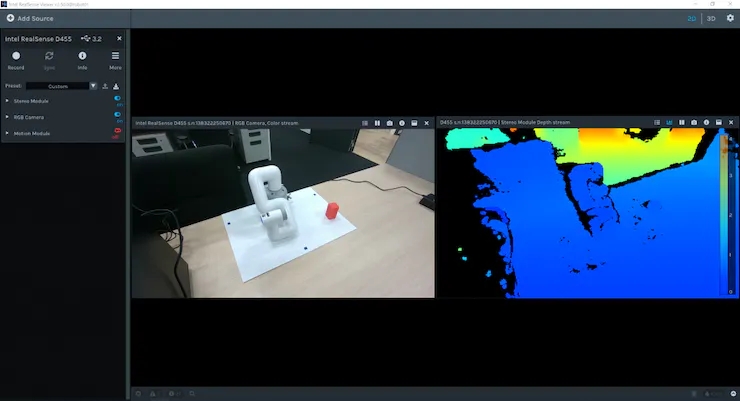
您可以使用右上角的 2D | 3D 按钮在 2D 和 3D 之间切换查看器。此外,您可以通过打开左侧的立体模块和RGB摄像头来查看深度信息和RGB信息。在 2D 中,您可以在 2D 中查看 RGB 和深度信息。在3D中,由深度估计红外立体相机估计的点云用深度彩色图和RGB相机信息着色,可以从各个角度查看。此外,内置 IMU 传感器的 D435i 和 D455 还可以通过运动模块获取姿态信息。接下来,我们来看看使用 ROS 包realsense_ros的 Rviz 点云。这可以使用 apt 安装。
$ sudo apt install ros-$ROS_DISTRO-realsense2-camera
实感摄像头在第一个终端启动,除了每个摄像头的信息外,还提供彩色点云,在第二个终端上启动 Rviz 进行可视化。
$ roslaunch realsense2_camera rs_camera.launch filter:=pointcloud$rviz
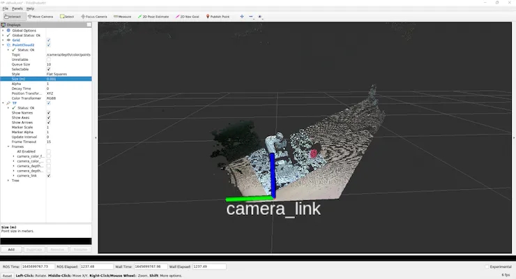
为了如图 9 所示查看点云,我们将使用 GUI 来调整设置。
首先,由于左侧显示面板中的全局选项的 固定框是地图,请单击它并将其更改为camera_link。
然后按显示面板底部的添加按钮,将弹出一个新窗口,列出可以在 Rviz 中显示的 ROS 消息类型。选择 rviz 组中间的 PointCloud2,然后按 OK 将 PointCloud2 添加到显示面板。
此外,如果您单击组中“主题”列右侧的空白并选择出现的 /camera/depth/color/points,则点云将显示在 Rviz 上。默认情况下,点云大小设置为 0.01 m,这是一个很大的值,因此点云相互重叠显示,但如果将其设置为 0.001 m 左右,您可以看到点云的获取非常精细。
此外,如果从“添加”中选择“TF”并添加它,则可以显示摄像机位置和方向(轴向)。默认情况下,RGB 相机原点和立体相机原点分别显示在世界坐标系和光学坐标系中。(camera_link似乎与立体相机起源相同)
保存设置,因为很难每次都弹出此按钮。
在工作区中创建目录配置以保存设置,在 Rviz 的文件中选择将配置另存为,命名创建的配置目录并保存。
$ rviz -d .rviz
如果您更改了某些内容,则可以每次通过保存配置更新相同的文件。如果您只是查看点云和相机位置,您可以使用realsense_viewer轻松做到这一点,但您可以使用 ROS 来处理原始数据。从这里开始就像是理解 ROS 消息数据含义的练习。
(但是,就个人而言,这是一个很大的绊脚石)
执行rs_camera.launch过滤器后:=点云。
让我们看一下 从另一个终端发送的 /camera/depth/color/points 主题的原始数据。
$ rostopic echo /camera/depth/color/points
当然这个值数组是点云数据,它应该用 xyz 坐标和位置中的 RGB 值表示,但很难直接读取。如果您查看数字,您会发现每个值都在 0 到 255 的范围内,并且类似的值以常规模式定期出现。但是,从这里猜测 x 代表哪里以及红色代表哪里是不合理的。
因此,首先,找出此消息的类型。
$ rostopic type /camera/depth/color/pointssensor_msgs/PointCloud2
我们现在知道消息类型是 sensor_msgs/PointCloud2。
另外,如果您从 ROS 文档中查看它,您可以看到如下内容。
Header header # header uint32 height # number of rows of datauint32 width # Number of columns of dataPointField[] fields # 1 point data structurebool is_bigendian # whether the big enduint32 point_step # number of bytes in a point (number of 8-bit numbers)uint32 row_step # number of data in a row (= width * point_step)uint8[] data # raw data (8bit row_step * height data array)bool is_dense # if true, then no invalid data
既然是点云,那么与2D图像不同,数据的顺序有什么意义?正如问题所暗示的那样,高度和宽度似乎没有意义。
目前尚不清楚持有可以从其他值计算并且不太可能使用的变量意味着什么,但结构是这样的。如果要查看每个的实际值,
$ rostopic echo /camera/depth/color/points/
通过执行此操作,您只能在数据中输出一个变量。例如,显示回point_step和字段给出。
$ rostopic echo /camera/depth/color/points/point_step–20—$ rostopic echo /camera/depth/color/points/fields–name: “x”offset: 0datatype: 7count: 1–name: “y”offset: 4datatype: 7count: 1–name: “z”offset: 8datatype: 7count: 1–name: “rgb”offset: 16datatype: 7count: 1—
输出将是 由于 point_step = 20,您可以看到一个点的数据由 20 个字节表示,您可以从字段的内容中看到这 20 个字节是如何组成的。
每个变量的含义是
名称:要表示的数据的名称
偏移量:对应的字节
数据类型:所表示数据的类型代码
计数:包含的数据项数
例如,x 坐标对应于从 0 到 3 的数据,类型代码为 7(对应于 float32),表示数据。 y 和 z 应该以相同的方式处理,但 RGB 也以相同的方式表示。当我查看与 RGB 对应的第 16 个到第 19 个值时,有 GBRA 顺序的十六进制值。到 float32 的转换似乎很难处理,因此似乎需要单独处理 xyz 坐标和 RGB。
现在我们知道了如何表示数据,让我们实际处理它。
(我认为有一个更智能,更快捷的方法来处理下一个脚本,所以如果你有任何建议,请)
将脚本目录添加到mycobot_test包中,并在其中添加 python 脚本。
$ cd /src/mycobot_test$ mkdir scripts$ cd scripts$ touch red_point_detection.py$ touch object_position_search.py
将依赖项添加到 CMakeLists.txt 并打包.xml。
# CMakeLists.txtfind_package(catkin REQUIRED COMPONENTS # Add rospy and sensor_msgs modules to be able to import rospy sensor_msgs ) catkin_package( # Add build package sensor_msgs ) # Add scripts to the executable directory catkin_install_python(PROGRAMS DESTINATION ${CATKIN_PACKAGE_BIN_DESTINATION}/scripts )Python rospy sensor_msgs rospy sensor_msgs
以下red_point_detection.py是一个脚本,它仅从点云中提取红色并创建新消息。
#!/usr/bin/env python3 import time, os, sys, signal, threading import numpy as np import rospy from sensor_msgs.msg import PointCloud2 class RedPointsDetectionNode(object): def __init__(self): super(RedPointsDetectionNode, self).__init__() self.data = PointCloud2() self.point_step = 20 self.R_COL = 18 self.G_COL = 17 self.B_COL = 16 rospy.init_node("red_points_detection_node") rospy.loginfo("red points detection start") # Subscriber def sub_pointcloud(self): def callback(data): self.sub_data = data sub = rospy.Subscriber("camera/depth/color/points", PointCloud2, callback = callback) rospy.spin() # Publisher def pub_red_pointcloud(self): pub = rospy.Publisher("red_point_cloud", PointCloud2, queue_size = 1) while not rospy.is_shutdown(): pub_data = self.red_point_detection(self.sub_data) pub.publish(pub_data) def red_point_detection(sub_data): red_point_data = sub_data red_pointcloud = np.array([d for d in sub_data.data]).reshape(-1, self.point_step) r_flags = red_pointcloud < 180 g_flags = red_pointcloud > 150 b_flags = red_pointcloud > 150 R_under_threshold_row = np.where(r_flags)[0][np.where(np.where(r_flags)[1]==self.R_COL)] G_over_threshold_row = np.where(g_flags)[0][np.where(np.where(g_flags)[1]==self.G_COL)] B_over_threshold_row = np.where(b_flags)[0][np.where(np.where(b_flags)[1]==self.B_COL)] not_red_row = np.unique(np.concatenate([R_under_threshold_row, G_over_threshold_row, B_over_threshold_row])) red_pointcloud = np.delete(red_pointcloud, not_red_row, axis=0).ravel().tolist() red_point_data.width = int(len(red_pointcloud) / self.point_step) red_point_data.height = 1 red_point_data.row_step = pub_pc2_data.width * self.point_step red_point_data.data = red_pointcloud rospy.loginfo("red pointcloud {}".format(int(len(red_pointcloud) / self.point_step))) return red_point_data # node start to subscribe and publish def start_node(self): sub_pointcloud = threading.Thread(target = self.sub_pointcloud) pub_red_pointcloud = threading.Thread(target = self.pub_red_pointcloud) sub_pointcloud.setDaemon(True) sub_pointcloud.start() pub_red_pointcloud.setDaemon(True) pub_red_pointcloud.start() sub_pointcloud.join() pub_red_pointcloud.join() if __name__ == "__main__": color_points_detector = ColorPointsDetectionNode() color_points_detector.start_node() pass
订阅者读取相机/深度/颜色/点数据,发布者仅从数据中提取红点并分发它们。处理红点以从原始点云中删除 RGB 值为f R < 180、G > 150 和 B > 150 的点。使用HSV比RGB更好,RGB容易受到照明条件的影响,但是这次在处理PointCloud2数据时很难转换为HSV,因此被搁置了。如果是C++,使用 PCL 似乎很容易进行 python 转换,但对于 python 来说毫无用处,因为很难编写其他过程)。
写入后,将其移动到工作区,catkin_make并执行它。
$ roslaunch realsense2_camera rs_camera.launch filters:=pointcloud$ rosrun mycobot_test red_point_detection.py$ rviz -d .rviz
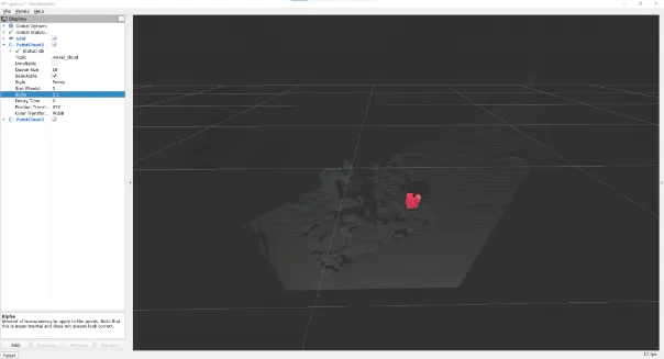
如果在 Rviz 中选择添加到 PointCloud2 消息中的 /red_point_cloud,则可以看到提取的点云,如图 10 所示。
object_position_search.py是一个脚本,用于查找提取的红点坐标的平均值。
# object_position_search.py#!/usr/bin/env python3 import time, os, sys, signal, threading import numpy as np import rospy from sensor_msgs.msg import PointCloud2 import sensor_msgs.point_cloud2 as pc2 from geometry_msgs.msg import Point class ObjectPositionSearchNode(object): def __init__(self): super(ObjectPositionSearchNode, self).__init__() rospy.init_node("object_position_search_node") rospy.loginfo("object position search start") self.object_position = Point() # Subscriber def sub_pointcloud(self): def callback(data): rospy.loginfo("subscribed pointcloud") xyz_generator = pc2.read_points(data, field_names = ("x", "y", "z"), skip_nans=True) xyz_list = [gen for gen in xyz_generator] list_num = len(xyz_list) x = np.array([xyz_list[i][0] for i in range(list_num) if (xyz_list[i][2] < 1.0 and xyz_list[i][2] > -1.0)]) y = np.array([xyz_list[i][1] for i in range(list_num) if (xyz_list[i][2] < 1.0 and xyz_list[i][2] > -1.0)]) z = np.array([xyz_list[i][2] for i in range(list_num) if (xyz_list[i][2] < 1.0 and xyz_list[i][2] > -1.0)]) self.object_position.x = np.average(x) self.object_position.y = np.average(y) self.object_position.z = np.average(z) sub = rospy.Subscriber("red_point_cloud", PointCloud2, callback = callback) rospy.spin() # Publisher def pub_target_position(self): pub = rospy.Publisher("object_position", Point, queue_size=1) while not rospy.is_shutdown(): rospy.loginfo("published object position: {:.5f}, {:.5f}, {:.5f}n".format(self.object_position.x, self.object_position.y, self.object_position.z)) pub.publish(self.object_position) def start_node(self): sub_pointcloud = threading.Thread(target = self.sub_pointcloud) pub_target_position = threading.Thread(target = self.pub_target_position) sub_pointcloud.setDaemon(True) sub_pointcloud.start() pub_target_position.setDaemon(True) pub_target_position.start() sub_pointcloud.join() pub_target_position.join() if __name__ == "__main__": object_position_searcher = ObjectPositionSearchNode() object_position_searcher.start_node() pass
在之前运行red_point_search.py的情况下,启动一个新终端并运行它。
$ rosrun mycobot_test object_position_search.py
它取red_point_cloud坐标值的平均值 并分布它们,同时记录这些值。坐标以米为单位,此脚本检索 1.0 米内的点。由于使用 rospy.loginfo 获得的坐标被记录下来,因此坐标被输出到终端。
sensor_msgs库中有一个point_cloud2模块,用于处理和读取 PointCloud2 数据,将坐标值从 4Byte 转换为 float32。内容很简单,但我很难理解这个模块的存在。如果您有其他复杂的消息数据,最好查看是否有随附的处理模块。这是真正意义上的设置和数据处理。关于数据处理,我认为您仍然需要找到更快处理(或改进算法)的方法,具体取决于应用程序。
6. 使用 ROS 将 myCobot 连接到实感 D455
现在实感数据处理已经完成,我想将其与myCobot结合使用。因此,最重要的是从实感相机坐标系到myCobot坐标系的转换。Rviz 上有一个 TF(变换)显示相机轴,但您需要了解这一点。顾名思义,它描述了描述一个坐标系与另一个坐标系之间关系的坐标变换。首先,让我们看看如果未设置此 TF 会发生什么情况。
$ roslaunch realsense2_camera rs_camera.launch filter:=pointcloud$ roslaunch mycobot_moveit mycobot_moveit_control.launch
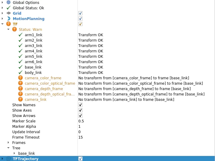
然后,您将在 Rviz 显示面板中看到一条警告,如图 11 所示。消息是相机的每个坐标系都没有变换到base_link(myCobot的起源)。
因此,让我们创建一个包,将 TF(坐标变换)从相机广播到 myCobot。很抱歉在C++和Python之间来回,但这次我将使用roscpp。首先创建一个包。
$ cd /src$ catkin_create_pkg tf_broadcaster roscpp$ cd tf_broadcaster$ touch src/tf_broadcaster.cpp
重写生成的tf_broadcaster.cpp CMakeLists.txt、package.xml如下所示。请注意,C++文件是一个类,因为它是为了练习在类中创建节点而创建的,但可以更轻松地编写。
// tf_broadcaster.cpp#include #include #include #include class TfBroadcaster { public: TfBroadcaster(); ~TfBroadcaster(); // Broadcast void BroadcastStaticTfFromCameraToMyCobot(); private: ros::NodeHandle nh_; // TF Broadcaster tf2_ros::StaticTransformBroadcaster static_tf_broadcaster_; // constant double PI_ = 3.1419265; }; TfBroadcaster::TfBroadcaster(){} TfBroadcaster::~TfBroadcaster(){} void TfMyCobotBroadcaster::BroadcastStaticTfFromCameraToMyCobot() { geometry_msgs::TransformStamped transformStamped; transformStamped.header.stamp = ros::Time::now(); transformStamped.header.frame_id = "camera_color_frame"; //link transformStamped.child_frame_id = "base_link"; // son link // Parallel movement transformStamped.transform.translation.x = -0.3; transformStamped.transform.translation.y = -0.3; transformStamped.transform.translation.z = -0.3; // Turning back tf2::Quaternion q; q.setEuler(0, 0, 0); transformStamped.transform.rotation.x = q.x(); transformStamped.transform.rotation.y = q.y(); transformStamped.transform.rotation.z = q.z(); transformStamped.transform.rotation.w = q.w(); static_tf_broadcaster_.sendTransform(transformStamped); } int main(int argc, char** argv) { ros::init(argc, argv, "tf_mycobot_broadcaster"); TfMyCobotBroadcaster tf_mycobot_broadcaster; tf_mycobot_broadcaster.BroadcastStaticTfFromCameraToMyCobot(); ros::Rate loop_rate(10); while(ros::ok()){ ros::spinOnce(); loop_rate.sleep(); } return 0; }# CMakeLists.txtcmake_minimum_required(VERSION 3.0.2) project(tf_broadcaster) find_package(catkin REQUIRED COMPONENTS roscpp geometry_msgs tf2_geometry_msgs) catkin_package( CATKIN_DEPENDS geometry_msgs tf2_geometry_msgs) include_directories(${catkin_INCLUDE_DIRS}) add_executable(tf_mycobot_broadcaster src/tf_mycobot_broadcaster.cpp) target_link_libraries(tf_mycobot_broadcaster ${catkin_LIBRARIES}) tf_broadcaster 0.0.0 The transform broadcaster package root TODO catkin tf2_geometry_msgs geometry_msgs
如您所见,我们设置 transformStamped 类的实例变量并广播该实例。广播变量类型是tf2_ros::StaticTransformBroadcaster,但这次我们使用静态TF,因为摄像机和机器人的位置是固定的。对于那些感兴趣的人,当职位关系随时间变化时,也可以使用动态 TF。
在这里,位置关系还不知道,所以值是暂时的,但我们可以组成显示,所以让我们尝试一下。此外,父链接camera_color_frame而不是camera_link,因为父链接的原点与点云坐标系匹配。 catkin_make后,像以前一样运行 rs_camera.launch 和 mycobot_moveit_control.launch,并在另一个终端中运行tf_broadcaster。
$ rosrun tf_broadcaster tf_broadcaster
这将广播成像仪和myCobot base_link之间的位置关系,因此TF警告消失。如果在此状态下添加点云,它将如图 12 所示。当然,相机和myCobot之间的位置关系是暂时的,因此相机看到的myCobot位置与Rviz中显示的模型位置不重叠。
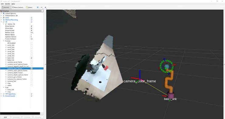
因此,接下来我们将校准从相机中看到的机器人的相对姿势和位置。
我认为还有另一种通过将相机固定在特定位置来指定位置关系的方法,但是这次我们标记三个点以确定机器人坐标,我们通过找到单位向量并相对于相机坐标系进行计算来校准位置关系。
你们中的一些人可能已经注意到,之前的照片是在已经连接标记的情况下拍摄的,但标记的放置方式如图 13 所示。

口粮标记
myCobot 的原点(底部中心)位于标记 2 和 3 的中点,标记 1 垂直于该原点的线段 2 和 3。
1.首先,重写red_point_detection.py并创建blue_point_detection.py以获得蓝色标记的点云。此处省略了该脚本,因为它只是重写了要提取的 RGB 范围。之后,我认为有多种方法可以从那里获得坐标转换,但这次是通过以下过程获得的。确定标记坐标 订阅标记点云
一个。将点云聚类为三个(通过 k 均值方法)
2. 确定原点和单位向量 标记 2 和 3 的中点是原点V_robot
一个。X 和 Y 的单位向量V_X和V_Y分别V_robot →标记 1、V_robot →标记 2。
b.Z 的单位向量是带有标记的平面和法线向量的叉积
3. 使用欧拉角创建从相机姿势到机器人姿势的旋转 theta_1 = 相机相对于水平面的仰角
a.theta_2 = 朝向相机前方的旋转角度
b.theta_3 = 相机与机器人前方方向之间的角度
4. 将 V-Z 方向的原点转换为 myCobot 的固定底座(2.7 厘米)
* 欧拉旋转开始的轴是任意的,因此结果会因所使用的库而异。(我认为不是每个人都费心这样做,所以我想知道您是否传递单位向量和两个坐标系的原点,如果有一些库将其转换为 TF。
以下脚本将添加到脚本目录中。
# mycobot_position_calibration.py#!/usr/bin/env python3 import time, os, sys, signal, threading import numpy as np import rospy from sensor_msgs.msg import PointCloud2 from geometry_msgs.msg import Point import sensor_msgs.point_cloud2 as pc2 class MyCobotPositionCalibrationNode(object): def __init__(self): super(MyCobotPositionCalibrationNode, self).__init__() rospy.init_node("mycobot_position_calibration_node") rospy.loginfo("mycobot position calibration start") # Subscriber def sub_pointcloud(self): def callback(data): self.data = data rospy.loginfo("subscribed pointcloud") xyz_generator = pc2.read_points(self.data, field_names = ("x", "y", "z"), skip_nans=True) xyz_list = [xyz for xyz in xyz_generator if (abs(xyz[0]) < 0.8 and abs(xyz[1]) < 0.8 and abs(xyz[2]) < 0.8)] xyz_array = np.array(xyz_list) if len(xyz_list) > 3: marker_centroids = self.kmeans(3, xyz_array) rospy.loginfo("n marker positionsn{}".format(marker_centroids)) translation = self.cal_translation(marker_centroids) rospy.loginfo("n translationn{}".format(translation)) sub = rospy.Subscriber("blue_point_cloud", PointCloud2, callback = callback) rospy.spin() # node start def start_node(self): sub_pointcloud = threading.Thread(target = self.sub_pointcloud) sub_pointcloud.setDaemon(True) sub_pointcloud.start() sub_pointcloud.join() # clustering method def kmeans(self, k, X, max_iter=30): # k: cluster num, X: numpy array data_size, n_features = X.shape centroids = X[np.random.choice(data_size, k)] new_centroids = np.zeros((k, n_features)) cluster = np.zeros(data_size) for epoch in range(max_iter): for i in range(data_size): distances = np.sum((centroids - X[i]) ** 2, axis=1) cluster[i] = np.argsort(distances)[0] for j in range(k): new_centroids[j] = X[cluster==j].mean(axis=0) if np.sum(new_centroids == centroids) == k: break centroids = new_centroids max_norm = 0 min_norm = 0 sorted_centroids = [] for centroid in centroids: norm = centroid[2] if norm > max_norm: sorted_centroids.append(centroid) max_norm = norm if min_norm == 0: min_norm = sorted_centroids[0][2] else: if norm > min_norm and min_norm != 0: sorted_centroids.insert(1, centroid) else: sorted_centroids.insert(0, centroid) min_norm = norm sorted_centroids = np.array(sorted_centroids) return sorted_centroids # translation angles calculation ## calculation def cal_translation(self, marker_points): # マーカー1, 2, 3の位置ベクトル #Position vector of marker 1, 2, 3 a_1, a_2, a_3 = marker_points # カメラからロボットへのベクトル #Vector from camera to robot V_robot = self.cal_robot_position_vector(a_2, a_3) # ロボットのXYZ単位ベクトル #XYZ unit vector of the robot V_X = (a_2 - V_robot) / (np.linalg.norm(a_2 - V_robot)) V_Y = (a_1 - V_robot) / (np.linalg.norm(a_1 - V_robot)) V_Z = self.cal_normal_vector(marker_points) # カメラの水平面に対する仰角 # Elevation angle of the camera relative to the horizontal plane theta_1 = - (np.pi/2 - self.cal_subtended_angle(-V_robot, V_Z)) # カメラの正面方向の回転角 #Rotation angle of the camera in the frontal direction V_Y_camera = np.array([0, 1, 0]) V_Y_camera_rotated = self.cal_rotate_vector_xaxis(V_Y_camera, -theta_1) theta_2 = - self.cal_subtended_angle(V_Z, -V_Y_camera_rotated) # カメラとロボットのそれぞれの正面方向とのなす角 #Angle between the camera and the respective frontal direction of the robot _, V_robot_projected_to_plane = self.cal_vector_projection(V_robot, V_Z) theta_3 = self.cal_subtended_angle(V_Y, V_robot_projected_to_plane) # mycobotの位置を土台の高さ0.027 m, V_Z方向に平行移動 # mycobot position at foundation height 0.027 m, parallel to V_Z direction V_robot = V_robot + 0.027*V_Z return V_robot, theta_1, theta_2, theta_3 ## vector and angle caluculation def cal_robot_position_vector(self, a_2, a_3): return (a_2 + a_3) / 2 def cal_normal_vector(self, marker_points): a_1 = marker_points[0] a_2 = marker_points[1] a_3 = marker_points[2] A_12 = a_2 - a_1 A_13 = a_3 - a_1 cross = np.cross(A_13, A_12) return cross / np.linalg.norm(cross) def cal_subtended_angle(self, vec_1, vec_2): dot = np.dot(vec_1, vec_2) norm_1 = np.linalg.norm(vec_1) norm_2 = np.linalg.norm(vec_2) return np.arccos( dot / (norm_1 * norm_2) ) def cal_vector_projection(self, org_vec, normal_vec): # org_vec: 射影したいベクトル # org_vec: the vector you want to project # normal_vec: 射影したい平面の法線ベクトル # normal_vec: Normal vector of the plane to be projected projected_to_vertical = np.dot(org_vec, normal_vec) * normal_vec projected_to_horizontal = org_vec + projected_to_vertical return projected_to_vertical, projected_to_horizontal def cal_rotate_vector_xaxis(self, vec, angle): rotate_mat = np.array([[1, 0, 0], [0, np.cos(angle), np.sin(angle)], [0, -np.sin(angle), np.cos(angle)]]) return vec.dot(rotate_mat) def cal_rotate_vector_yaxis(self, vec, angle): rotate_mat = np.array([[np.cos(angle), 0, -np.sin(angle)], [0, 1, 0], [np.sin(angle), 0, np.cos(angle)]]) return vec.dot(rotate_mat) def cal_rotate_vector_zaxis(self, vec, angle): rotate_mat = np.array([[np.cos(angle), np.sin(angle), 0], [-np.sin(angle), np.cos(angle), 0], [0, 0, 1]]) return vec.dot(rotate_mat) if __name__ == "__main__": mycobot_position_calibrator = MyCobotPositionCalibrationNode() mycobot_position_calibrator.start_node() pass
这次我们从最近的marker_1设置相机和机器人,根据它们的位置关系marker_2和marker_3,但需要注意的是,需要根据相机的位置进行调整。
构建完成后,相机、颜色搜索和校准节点将在三个终端中分别启动。
$ roslaunch realsense2_camera rs_camera.launch filter:=pointcloud$ rosrun mycobot_test blue_point_detection.py$ rosrun mycobot_test mycobot_position_calibration.py
这将记录变换 t_x, y, z (m) 和欧拉角 theta_1, 2, 3 (弧度) 到 mycobot_position_calibration.py 的终端。这些值由于点云数据收集和聚类而波动,因此这些值被多次取平均值。(在此设置中,平行平移和欧拉角都波动约 1%)
获取值后,在 tf_broadcaster.cpp 中重写临时值。
// tf_broadcaster.cpp~~ # それぞれ t_x,y,z と theta_1,_2,_3 に得られた値を入れる # Put the obtained values in t_x,y,z and theta_1,_2,_3 respectively transformStamped.transform.translation.x = t_z; transformStamped.transform.translation.y = -t_x; transformStamped.transform.translation.z = -t_y; tf2::Quaternion q; q.setEuler(theta_1, theta_2, theta_3); ~~
我正在寻找从camera_color_frame到base_link的TF,发现点编组坐标系camera_depth_optical_frame,计算后xyz方向不同(我没有注意到差异,我很困惑)所以 x = t_z,y = - t_x,z = - t_y。
重写并catkin_make后,启动节点。
$ roslaunch realsense2_camera rs_camera.launch filter:=pointcloud$ roslaunch mycobot_moveit mycobot_moveit_control.launch$ rosrun tf_broadcaster tf_broadcaster
然后反射摄像头和机器人的位置关系,点云上的机器人和Rviz所示的机器人模型可以叠加,如图14所示。
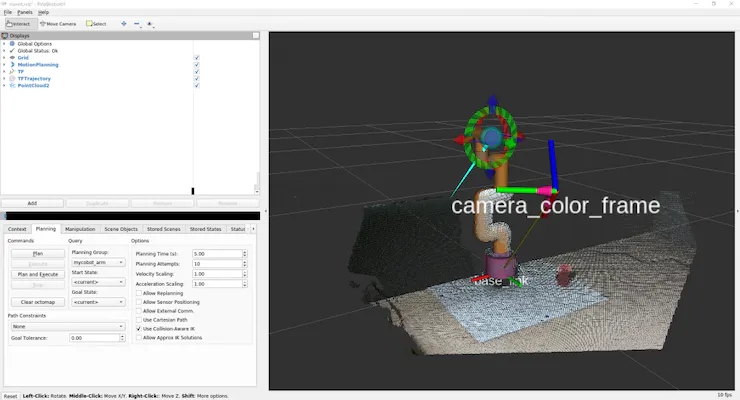
图 14:将从校准中获得的值设置为 TF 并广播它并不完美,但我能够将偏差保持在可接受的范围内,以便简单地到达并拾取物体。
当移动点云和叠加的机器人模型时,您可以看到这一点。
myCobot的关节有一点间隙,这使得很难做出精确的动作。
由于从实感获得的点云坐标系被转换为myCobot的坐标系,因此我们尝试将myCobot的尖端定位为对象。(我试图使用 MoveIt 访问它,但它被困在C++,所以我制作了一个可以使用 pymycobot 轻松操作的脚本)
由于坐标位于相机的光学坐标系中,因此请使用先前获得的平移和旋转将它们转换为myCobot坐标系。将以下内容添加到脚本目录。
# mycobot_reaching.py#!/usr/bin/env python3 import time, os, sys import numpy as np import quaternion from pymycobot.mycobot import MyCobot import rospy from geometry_msgs.msg import Point from tf.transformations import quaternion_from_euler class MyCobotReachingNode(object): def __init__(self): super(MyCobotReachingNode, self).__init__() rospy.init_node("mycobot_reaching_node") rospy.loginfo("mycobot reaching start") # メンバ変数 # mycobot インスタンス # member variable # mycobot instance port = "/dev/ttyUSB0" self.mycobot = MyCobot(port, baudrate="115200", timeout=0.1, debug=False) # 平行移動と回転 # 光学座標系→mycoboto座標系なので4.2節とXYZ軸が違うことに注意 # Translation and rotation # Note that the XYZ axes are different from those in section 4.2 because the optical coordinate system is a mycoboto coordinate system self.translation_from_camera_to_mycobot = np.array([t_x, t_y, t_z]) q = quaternion_from_euler(-theta_2, -theta_3, theta_1) self.rotation_from_camera_to_mycobot = quaternion.as_quat_array(q) # subscriber self.sub_point() # Subscriber def sub_point(self): def callback(data): rospy.loginfo("subscribed target point") self.mycobot_move(data) sub = rospy.Subscriber("object_position", Point, callback = callback) rospy.spin() # move mycobot def mycobot_move(self, point_data): # mycobot座標系への変換 # Convert to mycobot coordinate system target_point = np.array([point_data.x, point_data.y, point_data.z]) target_point -= self.translation_from_camera_to_mycobot target_point = quaternion.rotate_vectors(self.rotation_from_camera_to_mycobot, target_point) # mm単位のため*1000、手前中心付近にリーチングするためx-20mm, z+40mm # *1000 for mm increments, x-20mm, z+40mm for reaching around the center of the front coord_list = [target_point[0]*1000-20, -target_point[2]*1000, target_point[1]*1000+40, 0, 90, 0] self.mycobot.send_coords(coord_list, 70, 0) time.sleep(1.5) if __name__ == "__main__": reaching = MyCobotReachingNode() pass
这一次,我将调动我使用过的所有库和我制作的脚本。
您可以在 6 个终端中运行 rs_camera.launch、mycobot_moveit_control.launch、tf_broadcaster、red_point_detection.py、object_position_search.py、mycobot_reaching.py,但每次打开终端时,您都必须对其进行设置......调试会很困难,因此请创建自己的启动文件。
转到工作区,创建用于启动的目录和文件,并将启动路径添加到 CMakeLists.txt。
$ cd /src/mycobot_test$ mkdir launch$ cd launch$ touch mycobot_reaching.launch # CMakeLists.txt~~# Add launch fileinstall(FILES DESTINATION ${CATKIN_PACKAGE_SHARE_DESTINATION}/launch ) ~~
启动文件的结构很简单,只需将要同时运行的节点和启动文件中的启动文件排列在启动选项卡中即可。要执行节点,请在节点标记中写入任何节点名称,并像 rosrun 一样写入包名称和可执行文件名称。添加输出=“屏幕”,如果您希望输出显示在命令行上。
在引导文件中执行启动时,在包含标记中包含文件路径。尝试catkin_make并运行它。
$ roslaunch mycobot_test mycobot_reaching.launch
我能够移动myCobot来跟踪RealSense捕获的红色物体,就像在电影1中一样。
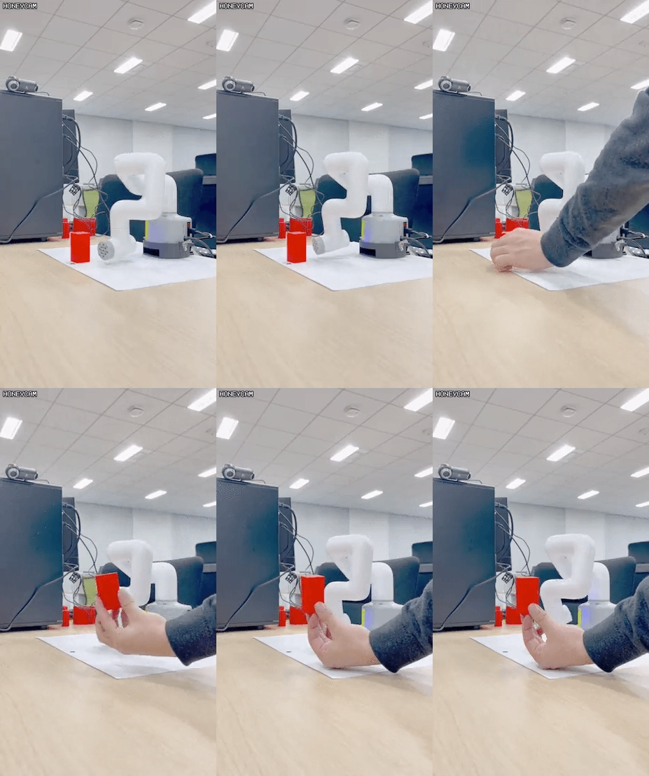
跟着项目跟着做之前有很多滞后,总觉得自己在各方面都学得还不够。
7. 总结
在本文中,我总结了如何使用 ROS 来协调 6 轴机械臂 myCobot 和深度摄像头实感 D455。我没有机器人开发的经验,包括ROS。我认为没有一个博客总结了我到目前为止从头开始尝试的内容,所以如果你买了一个机械臂或深度相机但不知道如何使用它,我希望它对那些想知道如何使用它的人有所帮助。另外,如果具有机器人开发经验或擅长数据处理的人可以指出最好做这样的事情,我将不胜感激。
这次我将我在模拟器中学到的强化学习模型应用于myCobot,并进行了拾取实验,所以我可能会写另一篇博客作为第2部分。
参考
1. 松林达志, 2022.12.21, 实感D455による空間認識でmyCobotを操作.
2. 阿尔伯特公司
审核编辑 黄宇
-
使用myCobot 280 Jeston Nano进行物体精确识别追踪2023-05-24 2692
-
MAX6394US455D3+T PMIC - 监控器2022-12-26 65
-
英特尔推出基于RealSense技术的3D人脸验证解决方案2021-01-19 3409
-
英特尔发布了RealSense ID 开发了一种面部识别系统2021-01-16 2669
-
英特尔RealSense ID结合了深度传感器与人脸识别系统2021-01-10 2828
-
英特尔RealSense D455发布,拍摄范围对上一代产品增大一倍2020-06-18 7263
-
RealSense400系列相机介绍和使用实践资料免费下载2019-07-09 1418
-
怎么将RealSense D415包文件转换为PCD2018-11-23 11052
-
哪个实际相机在2到5米范围内具有最佳的深度感知和物体识别平衡?2018-11-20 2757
-
英特尔将IMU搭载到RealSense摄像头D435i系统中2018-11-19 19324
-
如何将D435 realsense连接到intel aero现有的RealSense R200引脚2018-10-11 3540
-
Q455C/D/F阀门联动装置用户手册2017-10-24 1082
-
试用 Intel RealSense2017-09-25 4104
全部0条评论

快来发表一下你的评论吧 !

