

稳压二极管组成的基本稳压电路
电工基础电路图
描述
稳压二极管组成的基本稳压电路图:
图1电路是一个采用稳压二极管(齐纳二极管)的简单稳压器电路。

Figure 1. Simple Zener Shunt Stabilizer Circuit Diagram
The circuit in Figure 1 is a simple voltage stabilizer circuit that employs a zener diode and a single resistor. In this circuit, the zener diode, which is the stabilizing component, is in parallel (or in shunt) with the load, which is why it is also called a shunt stabilizing circuit. The value of R must be chosen so that a 'holding current' of 2 mA will flow into the zener diode even at the lowest input voltage and maximum load current. The zener diode maintains the output voltage level by 'conducting' the excess current to ground whenever the voltage across it becomes excessive.
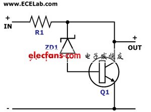
Figure 2. Amplified Zener Shunt Stabilizer Circuit Diagram
The circuit in Figure 2 is another shunt voltage stabilizer circuit that employs an additional NPN transistor to the simple circuit in Figure 1. In this circuit, the zener diode no longer has to conduct large currents to stabilize the output voltage. The transistor takes care of conducting the excess current whenever the current required by the load drops. This circuit is also known as the "amplified zener' shunt stabilizer.
-
稳压二极管是什么?有什么用处?2024-12-17 5453
-
稳压二极管怎么看型号 稳压二极管的工作原理2024-10-21 7203
-
稳压二极管怎么接入电路 稳压二极管型号参数2024-02-04 11297
-
什么是稳压二极管?稳压二极管的应用电路和原理分析2023-11-07 15681
-
稳压二极管稳压电路原理2023-08-27 6647
-
硅稳压二极管稳压电路原理说明2022-08-11 4620
-
稳压二极管的应用电路介绍2022-05-06 6998
-
什么是稳压二极管_稳压二极管的作用2021-01-01 42338
-
稳压二极管是什么_稳压二极管的故障特点2019-08-09 10730
-
稳压二极管的原理及应用2010-01-13 6027
-
稳压二极管稳压电路图2009-05-06 5594
-
加稳压二极管并联稳压电路2008-12-21 5520
全部0条评论

快来发表一下你的评论吧 !
