
Alarm Sounds When RF Transmitter is Out of Range
RF/无线
描述
This design idea explains how a 915MHz receiver can sound an alarm when a transmitter moves beyond a predetermined boundary.
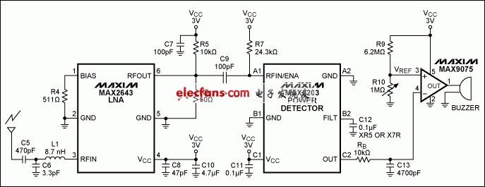
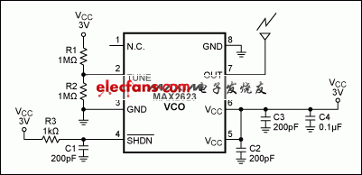
The receiver circuit of Figure 1 sounds an audio alarm when the MAX2623 transmitter (Figure 2) moves beyond a designated perimeter.The trigger distance depends on conditions and antenna design. In tests in a home environment with simple wire antennas, the distance was about five feet (1.5 meters).
The transmitter is a voltage-controlled oscillator, set to approximately 915MHz in the unlicensed industrial/scientific/medical (ISM) band. It has a tuning voltage of 1.5V = 3 × R2/(R1 + R2), which lets you easily adjust the frequency by varying resistor values R1 and R2.

Figure 1. This 915MHz receiver sounds an alarm when the comparator's inverting-input voltage drops below 400mV.

Figure 2. The transmitter consists of a voltage-controlled oscillator, tuned by R1 and R2 to approximately 915MHz.
The receiver consists of the MAX2643 low-noise amplifier (LNA), the MAX2203 power detector, the MAX9075 comparator, and a buzzer. When the transmitter is within range (carried by a child or a pet, for example), the receiver detects the RF signal and provides a voltage greater than 400mV at the inverting terminal of the comparator. Because the reference voltage at the comparator's noninverting terminal is preset to approximately 400mV by resistors R9 and R10 (VREF = 3 × R10/(R9 + R10)), the comparator output remains low.
When the transmitter moves outside the predetermined boundary, the detected RF produces less than 400mV at the comparator. The comparator then generates an output of approximately 3V, which turns on the buzzer and sounds an alert that the child or pet has wandered beyond the restricted perimeter. To increase the detection range, you can place additional LNAs or variable-gain amplifiers (VGAs) in front of the power detector. You can also increase or decrease the desired perimeter by adjusting R10 to change the comparator reference voltage VREF.
- 相关推荐
- 热点推荐
- RF
- Sounds
- Transmitter
-
STM8AF5189使用STVP,出现Address 0x9F2 is out of range and is ignored的原因?2024-05-07 524
-
AD9986: 4T2R Direct RF Transmitter and Observation Receiver Preliminary Data Sheet2021-01-27 815
-
使用HEW程序链接时提示“16-bits signed value is out of range -32768 32767”是什么原因?2020-05-19 3029
-
仪表放大器共模计算器AD620提示out of Range2018-10-26 1497
-
6632B在进入电压校准点P2时显示“OUT OF RANGE”2018-10-11 2572
-
水位告警器,Water level alarm2018-09-20 1480
-
报错:ERROR: argument to option -f ("value") is out of range2016-10-13 4916
-
When you buy used test equipme2010-07-16 790
-
Controlling Impedances When Ne2010-01-15 875
-
Medium range transmitter2009-12-22 1251
-
Light Is On When Power Is Out2009-04-27 1066
-
nRF904 RF and antenna layout2008-09-08 682
-
[图文]Zone Alarm System2006-04-16 1177
全部0条评论

快来发表一下你的评论吧 !

