ubuntu下编程——杰发科技AC7802x串口控制LED灯

描述

ubuntu20.04+vscode下对杰发科技的AC7802x Cortex-M0+进行编程、编译、下载等。

开发板

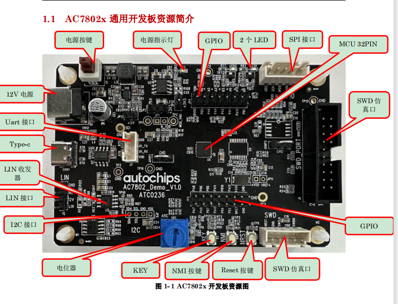
开发板为杰发科技的AC780x,板载的主控芯片为AC78022,32PIN。内核为Cortex-M0+。
编程

流程图

编程

控制部分的原理图

1、本次实验选用LED1来实现灯的开与关。原理图如下:

编程

编程

从原理图上看,LED1控制IO接到PA2,高电平制三极管导通,LED1亮,反之则关断。

串口选择

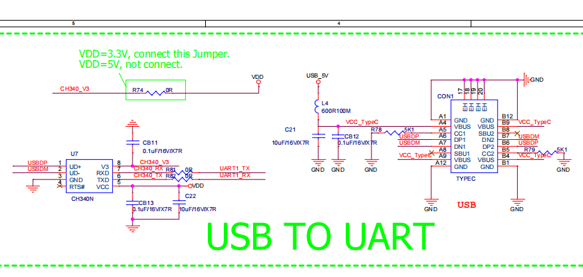
从开发板原理图上,uart1接到了ch340,并配备了typc接口,本次实验选用uart1为实验串口。
编程

实验步聚

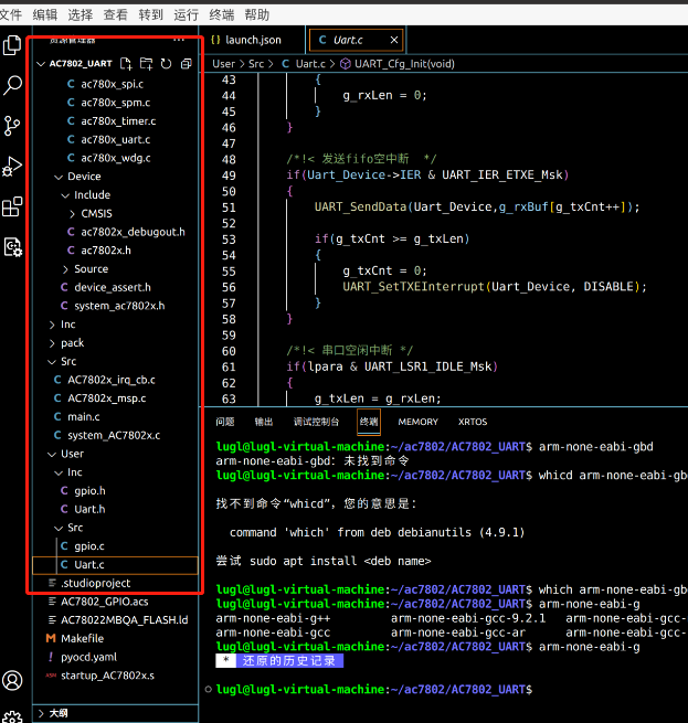
  1. 拷贝一份模版到AC7802_UART。并用vscode打开。

    编程

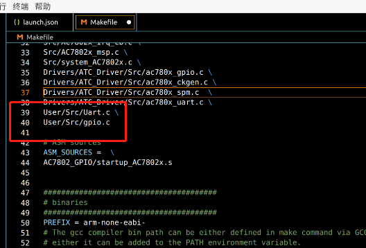
  2. 在User/Src下新建Uart.c,gpio.c,在Inc目录下新建Uart.h、gpio.h,并把Uart.c、gpio.c加入到makefile的source中
    编程

  3. 编写gpio.h 以及 gpio.c的Led初始化代码:

#ifndef _GPIO_H__
#define _GPIO_H__

#include "ac780x_gpio.h"

#define LED1_PORT           (GPIOA)
#define LED1_PIN            (GPIO_PIN2)


/*LED1动作定义.*/
#define LED1_ON             do{GPIO_SetPinLevel(LED1_PORT, LED1_PIN, GPIO_LEVEL_HIGH);}while(0)
#define LED1_OFF            do{GPIO_SetPinLevel(LED1_PORT, LED1_PIN, GPIO_LEVEL_LOW);}while(0)
#define LED1_TOGGLE         do{if(GPIO_GetPinLevel(LED1_PORT, LED1_PIN)){LED1_OFF;}else{LED1_ON;}}while(0)


void GPIO_LedInit(void);


#endif

gpio.c

#include "gpio.h"
#include "stdbool.h"

void GPIO_LedInit(void)
{
    /*初始化引脚功能,如果引脚上电后默认为GPIO,可省略掉初始化步骤.
      有部分引脚上电默认为非GPIO,则必须选择其功能为GPIO才能作为GPIO使用.*/
    GPIO_SetFunc(LED1_PORT, LED1_PIN, GPIO_FUN0);/*! 功能复用选择.*/


    /*! 设置LED引脚为GPIO输出.*/
    GPIO_SetDir(LED1_PORT, LED1_PIN, GPIO_OUT);


    LED1_ON;

}
  1. 编写uart.h、usrt.c内容如下:
#ifndef __UART_H__
#define __UART_H__
#include "ac780x_uart.h"

void UART_Cfg_Init(void);

#endif

uart.c

/* ===========================================  Includes  =========================================== */
#include < stdbool.h >
#include "ac780x_gpio.h"
#include "ac780x_uart_reg.h"
#include "Uart.h"


/* ============================================  Define  ============================================ */
#define RX_BUF_LEN   100U

/* ===========================================  Typedef  ============================================ */


/* ==========================================  Variables  =========================================== */
uint8_t g_rxLen  = 0;                 /*!< 串口接收长度变量 */        
uint8_t g_txLen  = 0;                 /*!< 串口发送长度变量 */
uint8_t g_txCnt  = 0;
uint8_t g_rxBuf[RX_BUF_LEN] = {0};    /*!< 串口接收数组 */     
uint8_t g_rec_state = 0;
/* ====================================  Functions declaration  ===================================== */


/* ======================================  Functions define  ======================================== */

/*!
 * @brief   串口回调函数
 *
 * @param   void *device:UART_Type pointer
            uint32_t wpara:UART lsr0 register
            uint32_t lpara:UART lsr1 register
 * @return  none
 */
void UART_Callback(void *device, uint32_t wpara, uint32_t lpara)
{
    UART_Type *Uart_Device = (UART_Type *)device;

    /*! 串口接收中断 */
    if(wpara & UART_LSR0_DR_Msk)
    {
        g_rxBuf[g_rxLen++] = UART_ReceiveData(Uart_Device);

        if(g_rxLen > RX_BUF_LEN)
        {
            g_rxLen = 0;
        }
    }

    /*!< 发送fifo空中断  */
    if(Uart_Device- >IER & UART_IER_ETXE_Msk)
    {
        UART_SendData(Uart_Device,g_rxBuf[g_txCnt++]);

        if(g_txCnt >= g_txLen)
        {
            g_txCnt = 0;
            UART_SetTXEInterrupt(Uart_Device, DISABLE);
        }
    }

    /*!< 串口空闲中断 */
    if(lpara & UART_LSR1_IDLE_Msk)
    {
        g_rec_state = 1;

        //UART_SetTXEInterrupt(Uart_Device, ENABLE);
    }
}

/*!
 * @brief   uart configuration init
 *
 * @param   none
 * @return  none
 */
void UART_Cfg_Init(void)
{
    UART_ConfigType uart_config;

    GPIO_SetFunc(GPIOA, GPIO_PIN4, GPIO_FUN3);    /*! uart tx */
    GPIO_SetFunc(GPIOA, GPIO_PIN5, GPIO_FUN3);    /*! uart rx */

    uart_config.baudrate   = 115200;              /*! 波特率115200 */
    uart_config.dataBits   = UART_WORD_LEN_8BIT;  /*! 数据8bit */
    uart_config.stopBits   = UART_STOP_1BIT;      /*! 停止位1bit */
    uart_config.fifoByteEn = DISABLE;   
    uart_config.sampleCnt  = UART_SMP_CNT0;       /*! 16倍采样 */
    uart_config.callBack   = UART_Callback;       /*! 回调函数设置 */

    UART_Init(UART1,&uart_config);                /*! 串口初始化 */

    UART_SetRXNEInterrupt(UART1, ENABLE);         /*! 串口接收中断使能 */

    UART_SetIdleFuncEn(UART1, ENABLE);
    UART_SetIdleInterrupt(UART1, ENABLE);         /*! 使能串口空闲中断 */

    NVIC_SetPriority(UART1_IRQn, 3);              /*! 串口中断优先级 */
    NVIC_ClearPendingIRQ(UART1_IRQn);
    NVIC_EnableIRQ(UART1_IRQn);
}

编程的要点主要是串口中断中的空闲中断,如果触发了空闲中断,我们就认为接收一次命令完毕,更新接收标志为1.为主程序来判断提供标志位。

  1. 编写主程序如下:
/* --------------------------------- Includes -------------------------------*/
#include "main.h"
#include "ac780x_uart_reg.h"
#include "Uart.h"
#include "gpio.h"

/* --------------------------------- Function Prototypes --------------------*/
void SystemClock_Config(void);

extern uint8_t g_rxLen;                 /*!< 串口接收长度变量 */        

extern uint8_t g_rxBuf[RX_BUF_LEN];    /*!< 串口接收数组 */     
extern uint8_t g_rec_state;

/**
  * @brief  The application entry point.
  *
  * @retval int
  */
int main(void)
{

    SystemClock_Config();
    InitDelay();
    GPIO_LedInit();

    UART_Cfg_Init();
    while(1)
    {
      if(g_rec_state == 1)
      {
        g_rec_state = 0;
        if(g_rxLen >=4)
        {
          if(g_rxBuf[0] == 'L' && g_rxBuf[1] == 'E' && g_rxBuf[2] == 'D' && g_rxBuf[3] == 'O' && g_rxBuf[4] == 'N')
          {
            LED1_ON;
          }
          else if(g_rxBuf[0] == 'L' && g_rxBuf[1] == 'E' && g_rxBuf[2] == 'D' && g_rxBuf[3] == 'O' && g_rxBuf[4] == 'F'  && g_rxBuf[5] == 'F')
          {
            LED1_OFF;
          }
          g_rxLen = 0;
        }
      }
      

    }

}


/**
    * @brief System Clock Configuration
    * @retval None
    */
void SystemClock_Config(void)
{
    CKGEN_SetSysclkSrc(SYSCLK_SRC_INTERNAL_OSC);
    CKGEN_SetSysclkDiv(SYSCLK_DIVIDER_1);
    CKGEN_SetAPBClockDivider(APBCLK_DIVIDER_2);
}


/**
  * @brief  This function is executed in case of error occurrence.
  * @param  file: The file name as string.
  * @param  line: The line in file as a number.
  * @retval None
  */
void Error_Handler(char *file, int line)
{
    /* USER CODE BEGIN Error_Handler_Debug */
    /* User can add his own implementation to handle the driver error */
    while(1)
    {
    }
    /* USER CODE END Error_Handler_Debug */
}

/************************ (C) COPYRIGHT AutoChips *****END OF FILE****/
  1. 编译,然后执行make flash:
lugl@lugl-virtual-machine:~/ac7802/AC7802_UART$ make
arm-none-eabi-gcc -c -mcpu=cortex-m0plus -mthumb    -IInc -IDrivers/ATC_Driver/Inc -IDrivers/Device/Include -IDrivers/Device -IDrivers/Device/Include/CMSIS -IUser/Inc -O0 -Wall -fdata-sections -ffunction-sections -g -gdwarf-2 -MMD -MP -MF"build/Uart.d" -Wa,-a,-ad,-alms=build/Uart.lst User/Src/Uart.c -o build/Uart.o
arm-none-eabi-gcc build/main.o build/AC7802x_irq_cb.o build/AC7802x_msp.o build/system_AC7802x.o build/ac780x_gpio.o build/ac780x_ckgen.o build/ac780x_spm.o build/ac780x_uart.o build/Uart.o build/gpio.o build/startup_AC7802x.o -mcpu=cortex-m0plus -mthumb   -specs=nano.specs -TAC78022MBQA_FLASH.ld  -lc -lm -lnosys  -Wl,-Map=build/AC7802_UART.map,--cref -Wl,--gc-sections -o build/AC7802_UART.elf
arm-none-eabi-size build/AC7802_UART.elf
   text    data     bss     dec     hex filename
  12384      12    2228   14624    3920 build/AC7802_UART.elf
arm-none-eabi-objcopy -O ihex build/AC7802_UART.elf build/AC7802_UART.hex
arm-none-eabi-objcopy -O binary -S build/AC7802_UART.elf build/AC7802_UART.bin
lugl@lugl-virtual-machine:~/ac7802/AC7802_UART$ make flash
pyocd flash ./build/AC7802_UART.elf --target ac78022mbqa
0000415 I Loading /home/lugl/ac7802/AC7802_UART/build/AC7802_UART.elf [load_cmd]
[==================================================] 100%
0001737 I Erased 4096 bytes (8 sectors), programmed 4096 bytes (8 pages), skipped 8704 bytes (17 pages) at 9.46 kB/s [loader]

实现效果

我们打开串口助手,发送LEDON、LEDOFF就可以控制LED灯的亮与灭了。

打开APP阅读更多精彩内容
声明:本文内容及配图由入驻作者撰写或者入驻合作网站授权转载。文章观点仅代表作者本人,不代表电子发烧友网立场。文章及其配图仅供工程师学习之用,如有内容侵权或者其他违规问题,请联系本站处理。 举报投诉

全部0条评论

快来发表一下你的评论吧 !

×
20
完善资料,
赚取积分