
如何设计边沿采样的触发器呢?
电子说
描述
下降沿采样寄存器
01
在设计双边沿采样电路(Dual-edge triggered flip-flop)之前,先从单边沿采样电路设计(Edge capture register)开始。
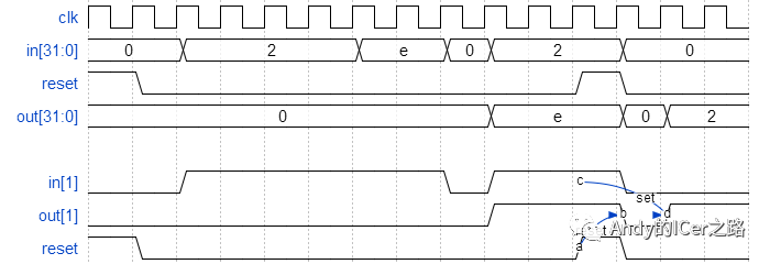
题目:对于32位向量中的每个位,当输入信号从一个时钟周期的1变为下一个时钟周期的0时捕获。“捕获”表示在寄存器复位(同步复位)之前,输出将保持为1。
每个输出位的行为都类似于SR触发器:应在从1到0的跳变发生后的周期内将输出位设置(设置为1)。复位为高电平时,应在时钟的上升沿将输出位复位(清零)。如果以上两个事件同时发生,则复位优先。
在下面的示例波形中,为清楚起见,分别显示了reset,in [1]和out [1]。

这里要注意的是,这题与专题十的边缘检测不一样,本题是边缘“捕获”,即捕获到下降沿之后要一直保持1,直到复位信号为1才变位0。
module top_module (
    input clk,
    input reset,
    input [31:0] in,
    output [31:0] out
);
    reg[31:0] p1,in_last;
    always@(posedge clk) begin
        in_last <= in;
        if(reset)
            out <= 0;
        else begin
            p1 = in_last&~in;
            if(p1!=0)
                out <= p1|out;
            else
                out <= out;
        end
    end
endmodule
第9行 in_last <= in ; 记录信号in上一个cycle的状态;
第13行 p1 = in_last&~ in ;检测下降沿,简答来说就是检测输入信号in由1变0。
第14-17行的mux是保持“捕获”or“未捕获”状态,**if(p1!=0)**表示有下降沿信号发生,**out <= p1|out; **表示继续更新置1的位数;else p1==0,则out保持原来的状态,即已经被捕获的位保持“1”状态、还未被捕获的位保持“0”状态。
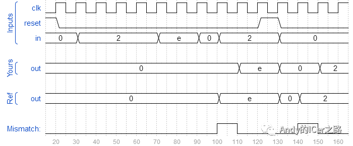
正确的仿真波形如下图所示:

这里有一个很重要的细节: 第十三行用的是阻塞赋值p1 = in_last&~in; 。即要等p1信号更新完毕之后才能进行if的判断,假如用非阻塞语句会导致out会晚一个周期才有反应,错误波形如下:

双边沿采样触发器
02
题目:您熟悉在时钟的上升沿或时钟的下降沿触发的触发器。双沿触发触发器在时钟的两个边沿触发。但是,FPGA没有双沿触发触发器,因此始终不接受@(posedge clk或negedge clk)作为合法敏感性列表。
构建功能上类似于双沿触发触发器的电路:

module top_module (
    input clk,
    input d,
    output q
);
    reg q1,q2;
    always@(posedge clk)begin
        q1 <= d;
    end

    always@(negedge clk)begin
        q2 <= d;
    end
    assign q = clk?q1:q2;

endmodule
还有一种可行的方案:
module top_module(
  input clk,
  input d,
  output q);

  reg p, n;

  // A positive-edge triggered flip-flop
    always @(posedge clk)
        p <= d ^ n;

    // A negative-edge triggered flip-flop
    always @(negedge clk)
        n <= d ^ p;

    // Why does this work?
    // After posedge clk, p changes to d^n. Thus q = (p^n) = (d^n^n) = d.
    // After negedge clk, n changes to p^n. Thus q = (p^n) = (p^p^n) = d.
    // At each (positive or negative) clock edge, p and n FFs alternately
    // load a value that will cancel out the other and cause the new value of d to remain.
    assign q = p ^ n;
endmodule
-
同步触发器和边沿触发器的区别2024-08-12 3551
-
边沿触发器的类型有哪些2024-08-11 1914
-
边沿触发器的状态变化由什么控制2024-08-09 1742
-
一文详解边沿触发器2023-03-16 12938
-
什么是边沿触发器_边沿D触发器介绍2018-01-31 73149
-
jk边沿触发器工作原理2018-01-30 38491
-
边沿触发SR触发器2010-08-10 7101
-
CMOS触发器在CP边沿的工作特性研究2009-10-17 2370
全部0条评论

快来发表一下你的评论吧 !

