
用MAX2742构建GPS接收机
描述
利用集成CMOS RF前端GPS接收机MAX2742,附加极少的外部元件,即可构成一个完整的GPS解决方案。
概述
MAX2742是CMOS、单芯片、GPS前端下变频器。这款性能优异的器件只需消耗极低的功率(32mW,2.4V),并且不需要昂贵的IF SAW滤波器和体积庞大的分立IF SAW滤波器。MAX2742片内集成了低噪声放大器(LNA)、混频器、BPF、自动增益控制放大器(AGC)、本振合成器、时钟缓冲器和内部数字采样器。
该器件能够与许多商用GPS基带IC接口,适合多种应用,其中包括:汽车导航、远程信息处理、自动安全监控、资产跟踪、定位服务(LBS)及其它消费类电子产品。用MAX2742构成一个完整的GPS RF解决方案只需少量的外部元件。以下给出了系统框图。
MAX2742工作于18.414MHz*晶体或TXCO,提供差分或单端** IF输出(1.023MHz)。总的信号变换增益为120dB,噪声系数4.5dB。IF信号以18.414MHz的参考时钟频率进行采样。
完备的GPS RF前端方案
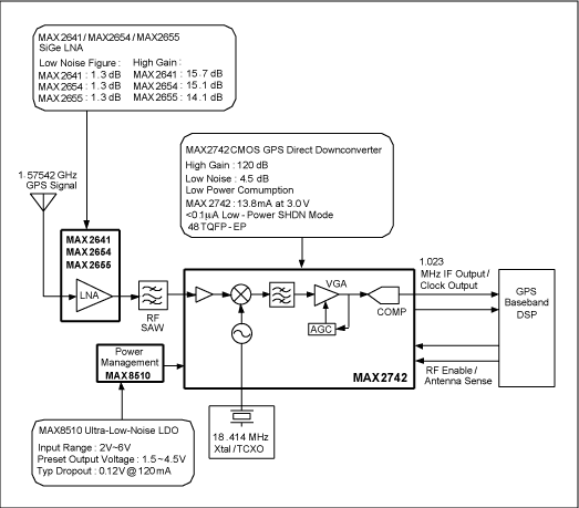
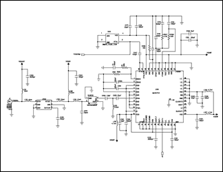
图1给示了Maxim完整的GPS RF方案的重要结构框图和特点。表1给出了框图说明,表2给出了级联特性。图2所示电路是用MAX2742构成的GPS接收机的RF电路。

图1. GPS RF前端框图
表1. RF部分系统框图
| Block | Description | Note |
| GPS antenna | Active GPS antenna, commonly has ~1.5dB NF and ~20dB gain | |
| LNA | MAX2641/MAX2654/MAX2655 LNA | External LNA is required when active GPS antenna may not be present. |
| RF SAW | RF bandpass filter centered at 1575.42MHz | RF BPF is required for jammer immunity |
| Power management | MAX8510 low-noise LDO | |
| RF downconverter | MAX2742 | |
| Reference clock | 18.414MHz crystal/TCXO | |
| DSP | Baseband processor |
表2. 系统级联特性
| Specification | Cascaded Performance | Note |
| Gain | 131dB | Without active antenna, assuming 15dB external LNA gain, 3dB BPF loss, and 1dB matching network loss |
| Noise Figure | 1.9dB | Without active antenna, assuming 1.5dB external LNA NF |
| Power Consumption | 20mA | MAX2744+MAX2654 as an example |

图2. 用MAX2742构成的GPS RF部分原理图
完备的GPS接收机方案
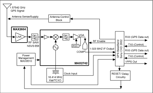
构建一个完整的GPS接收机,除了RF和基带IC外,还需要其它电路。如图3所示,天线电源控制电路、复位电路、延时电路等都是必需的。表3给出了框图说明;表4给出了级联特性。

图3. 完整的GPS接收机框图
表3. 系统各部分电路
| Block | Description | Note |
| GPS Antenna | GPS antenna | Refer to the RF portion for details. |
| LNA | MAX2654 LNA | Refer to the RF portion for details. |
| RF SAW | RF bandpass | Refer to the RF portion for details. |
| Power management | MAX8510 low-noise LDO | |
| RF downconverter | MAX2742 | |
| Reference clock | 18.414MHz TCXO | The TCXO also supplies the baseband clock. In this reference design, GPS clock output from the MAX2742 is not used. |
| GPS baseband | Sony CXD2932 | The CXD2932 also controls active antenna supply, RESET function. See details below. |
| Antenna control block | Antenna supply control with p-MOSFET and current-sense resistor | The sense resistor feeds the antenna supply information back to CXD2932. There are three possible conditions: normal, short, and open. |
| RESET/delay circuitry | Different levels of RESET, and delay circuit required by CXD2932 | To ensure successful startup, CXD2932 requires two RESET signals 100ms apart. |
| Baseband interface | TX: external control command | |
| RX: GPS data out | Data-rate programmable | |
| 1PPS: one pulse-per-second signal | This signal is aligned with GPS atomic clock. |
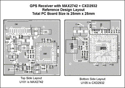
图4
给出了参考设计的实际PCB布线图。这个完整的解决方案仅占用25mm x 25mm的PCB空间。

图4. GPS接收机PCB布线
表4. 模块性能(LNA + MAX2742 + SONY CXD2932)
| No. | Parameter | Symbol | Conditions | System Specifications | Maxim Target | Measured | Units |
| 1 | Power supply | VCC | (Note 1) | 2.7 ~ 3.6 | T.C. | V | |
| 2 | Current consumption | ICC | VCC = 3.0V | 91 | 88 | mA | |
| 3.1 | Sensitivity | Sens | Acquisition | Tracking | -145 | -145 | dBm |
| 3.2 | -138 | -138 | |||||
| 4 | TTFF | TFC | Cold start | 58 (typ) | 60 (max) | s | |
| 5 | TFW | Warm start | 45 | 30 (max) | s | ||
| 6 | TFH | Hot start | 17 | 6 (max) | s | ||
| 7 | Position drift range | PR | 95% possibility | 100 | 90 | ft | |
| 8 | 1PPS output accuracy | 1PPS | 1 | N.M. | ns |
注1:T.C. = 测试条件,N.M. = 没有测试。
审核编辑:郭婷
-
微型GPS接收机的设计2023-11-07 528
-
完整的独立GPS接收机方案,采用MAX27422023-03-03 2848
-
基于FPGA的GPS接收机实现2021-04-09 1443
-
基于DSP的GPS软件接收机的设计2021-03-30 995
-
基于MCU的手持GPS接收机的设计2017-02-07 780
-
maxim推出通用型支持GLONASS的GPS接收机MAX2769B2011-09-11 3470
-
GPS接收机基本工作原理2011-09-03 23340
-
GPS\DGPS概述和基于Maxim GPS芯片的RF前端设2010-06-03 1425
-
GPS的接收机2010-01-29 677
-
国内外测地型GPS接收机简介2010-01-14 1123
-
什么是GPS接收机2009-12-31 2764
-
GPS和DGPS概述和完整的RF前端设计2008-12-13 1696
-
GPS接收机原理图2008-08-06 3207
-
MAX2742 pdf2008-06-30 977
全部0条评论

快来发表一下你的评论吧 !

