

【产品应用】AWorksLP 样例详解(MR6450)—— HWTimer
描述
AWorksLP 对外设进行了高度抽象化,为同一类外设提供了相同的接口,应用程序可以轻松跨平台。本文以MR6450平台为例,介绍AWorksLP HWTimer 外设基本用法。 简介在AWorksLP中将硬件定时器分为了4类,即延时型、计数型、周期型和输入捕获型硬件定时器。
- 延时型硬件定时器:
由硬件定时器外设提供的延时功能。
- 计数型硬件定时器:
提供较精确的类似时间戳的功能。
- 周期型硬件定时器:
可设置中断频率的计数器,不仅能提供计数器的功能,也能根据中断频率提供更精确的定时。
- 输入捕获定时器:可测量脉冲宽度或者测量频率。
接口介绍延时型硬件定时器:
函数原型 | 简要描述 |
aw_err_t aw_hwtimer_delay (int fd, struct aw_timespec *p_tv); | 延时 |
aw_err_t aw_hwtimer_delay_cancel (int fd); | 取消延时 |
计数型硬件定时器:
函数原型 | 简要描述 |
aw_err_t aw_hwtimer_count_start (int fd); | 启动一个计数型硬件定时器 |
aw_err_t aw_hwtimer_count_stop (int fd); | 停止一个计数型硬件定时器 |
aw_err_t aw_hwtimer_count_get (int fd, uint64_t *p_count); | 读取计数值 |
aw_err_t aw_hwtimer_count_rate_get (int fd, uint32_t *p_rate); | 获取计数时钟频率 |
aw_err_t aw_hwtimer_count_rate_set (int fd, uint32_t rate); | 设置计数时钟频率 |
aw_err_t aw_hwtimer_count_rate_set_accurate (int fd, uint32_t rate_numerator, uint32_t rate_denominator); | 以精确化的方式设置计数时钟频率 |
aw_err_t aw_hwtimer_count_rate_get_accurate (int fd, uint32_t *p_rate_numerator, uint32_t *p_rate_denominator); | 获取计数时钟频率的精确描述 |
周期型硬件定时器:
函数原型 | 简要描述 |
aw_err_t aw_hwtimer_period_wait (int fd, uint32_t wait_ms); | 等待定时器周期中断 |
aw_err_t aw_hwtimer_period_intr (int fd); | 打断周期型定时器的等待操作 |
aw_err_t aw_hwtimer_period_start (int fd); | 启动定时器 |
aw_err_t aw_hwtimer_period_stop (int fd); | 停止定时器 |
aw_err_t aw_hwtimer_period_count_get (int fd, uint64_t *p_count); | 读取计数值 |
aw_err_t aw_hwtimer_period_count_freq_get (int fd, uint32_t *p_rate); | 获取周期型定时器的硬件计数频率(不是中断频率) |
aw_err_t aw_hwtimer_period_count_freq_get_frac (int fd, aw_hwtimer_rate_t *p_rate); | 以更精确的分数形式获取周期型定时器的硬件计数频率(不是中断频率) |
aw_err_t aw_hwtimer_period_intr_freq_set (int fd, uint32_t intr_freq); | 设置中断频率 |
aw_err_t aw_hwtimer_period_intr_freq_get (int fd, uint32_t *p_intr_freq); | 获取中断频率 |
aw_err_t aw_hwtimer_period_intr_freq_set_frac (int fd, aw_const aw_hwtimer_rate_t *p_intr_freq); | 设置中断频率(以更精确的分数形式) |
aw_err_t aw_hwtimer_period_intr_freq_get_frac (int fd, aw_hwtimer_rate_t *p_intr_freq); | 获取中断频率(以更精确的分数形式) |
输入捕获型硬件定时器:
函数原型 | 简要描述 |
aw_err_t aw_hwtimer_cap_start (int fd); | 启动输入捕获型硬件定时器 |
aw_err_t aw_hwtimer_cap_stop (int fd); | 停止输入捕获型硬件定时器 |
aw_err_t aw_hwtimer_cap_read (int fd, uint64_t *p_cap_val, uint32_t timeout_ms); | 读取一个捕获到的事件的计数值 |
aw_err_t aw_hwtimer_cap_intr (int fd); | 打断阻塞read读操作 |
aw_err_t aw_hwtimer_cap_config_set (int fd, aw_const aw_hwtimer_cap_config_t *p_config); | 配置输入捕获型硬件定时器 |
aw_err_t aw_hwtimer_cap_config_get (int fd, aw_hwtimer_cap_config_t *p_config); | 获取输入捕获型硬件定时器的配置 |
使用样例AWorksLP SDK相关使用请参考《AWorksLP SDK快速入门(MR6450)——开箱体验》一文,本文不在赘述。1. 周期型定时器{SDK}\demos\peripheral\hwtimer路径下为硬件定时器例程,默认运行的是demo_hwtimer.c 周期型定时器的代码,例程关键代码如下:
/** * \brief 硬件定时器中断服务函数。 * \param[in] p_arg : 任务参数 */static void mytimer_isr (void *p_arg){ aw_gpio_toggle((int)p_arg); aw_kprintf("enter isr \n\r");}
/** * \brief hwtimer 测试函数 */aw_local void* __task_handle (void *arg){ int fd; aw_err_t ret; uint32_t count = 5; aw_hwtimer_rate_t p_intr_freq;
p_intr_freq.rate_denominator = 5; p_intr_freq.rate_numerator = 1;
fd = aw_open(CONFIG_DEMO_HWTIMER_PEROID_DEV_NAME, AW_O_RDWR, 0); if (fd < 0) { aw_kprintf("hwtimer open failed:%d \n\r", fd); while(1); }
ret = aw_hwtimer_period_intr_freq_set_frac(fd, &p_intr_freq); while (count) { aw_hwtimer_period_wait(fd, 500); mytimer_isr(arg); count --; }
// 配置每秒中断2次 ret = aw_hwtimer_period_intr_freq_set(fd, 2);
ret = aw_hwtimer_period_start(fd); if (ret != AW_OK) { aw_kprintf("Timer allocation fail!\n"); }
ret = aw_hwtimer_period_wait(fd, AW_WAIT_FOREVER);
while (1) { aw_hwtimer_period_wait(fd, AW_WAIT_FOREVER); mytimer_isr(arg); }
for (;;) { aw_mdelay(1000); } aw_close(fd);
return 0;}
在代码中先使用了aw_hwtimer_period_intr_freq_set_frac 接口,以分数的形式设置中断频率,使用aw_hwtimer_period_start接口启动定时器。在循环中使用aw_hwtimer_period_wait 接口阻塞等待中断的产生、中断产生后继续执行mytimer_isr函数使LED 灯状态翻转,由于设置的频率为五分之一,所以5秒LED 灯的状态翻转一次;循环一定次数后用aw_hwtimer_period_intr_freq_set 接口设置中断频率为2HZ,循环等待中断、翻转LED。实验现象为LED灯先以5s的频率闪烁,同时串口打印同时信息。闪烁一定次数后以0.5s的频率LED闪烁,同时串口打印信息。
下表为使用硬件周期型定时器,在中断中进行引脚翻转,通过逻辑分析仪所测量出的实际数据,在使用设计时可作为部分参考依据。
定时时间(s) | 实际时间(s) |
0.010000000 | 0.010000115 |
0.020000000 | 0.019999940 |
0.030000000 | 0.029999980 |
0.040000000 | 0.040000035 |
0.050000000 | 0.049999830 |
0.100000000 | 0.100000075 |
0.200000000 | 0.200000020 |
0.500000000 | 0.500000070 |
1.000000000 | 1.000000760 |
2.000000000 | 1.999999340 |
3.000000000 | 3.000002760 |
4.000000000 | 4.000001980 |
5.000000000 | 5.000004310 |
10.000000000 | 10.000008300 |
2. 计数型定时器在config配置脚本中选择hwtimer count计数型定时器测试如图1所示。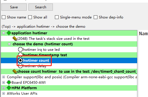 图1 计数型定时器例程保存后重新Build工程,编译好后运行的是demo_hwtimer_count.c的代码,例程关键代码如下:
aw_local void* __task_handle (void *arg){ uint32_t count = 0; int fd, led_fd; int ret; uint32_t start_count; fd = aw_open(CONFIG_DEMO_HWTIMER_PEROID_DEV_NAME, AW_O_RDWR, 0); if (fd < 0) { aw_kprintf("hwtimer open fail! :%d\n",fd); return; } /* 打开设备会点亮LED */ led_fd = aw_open("/dev/led_run", AW_O_RDWR, 0); if (led_fd < 0) { aw_kprintf("led open fail! :%d\n", led_fd); aw_close(fd); return; } ret = aw_hwtimer_count_rate_get(fd, &start_count); if (ret != AW_OK) { aw_kprintf("Timer count rate get fail!\n"); aw_close(fd); aw_close(led_fd); return; } // 设置时钟频率 ret = aw_hwtimer_count_rate_set(fd, start_count/2); if (ret != AW_OK) { aw_kprintf("Timer count rate set fail!\n"); aw_close(fd); aw_close(led_fd); return; } ret = aw_hwtimer_count_start(fd); if (ret != AW_OK) { aw_kprintf("Timer start fail!\n"); aw_close(fd); aw_close(led_fd); return; } for (;;) { aw_led_toggle(led_fd); aw_mdelay(500); aw_led_toggle(led_fd); aw_hwtimer_count_get(fd, &count); aw_kprintf("Count is %d\r\n", count); } aw_close(fd); aw_close(led_fd); return 0;}
在上述代码中使用了aw_hwtimer_count_rate_get接口获取改定时器时钟频率,可以在调试模式下查看获取到的参数,为100M 如图2所示。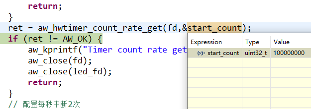 图2 查看参数使用aw_hwtimer_count_rate_set接口设置定时器时钟的频率为50M,使用aw_hwtimer_count_start接口开启定时器,使用aw_hwtimer_count_get接口在循环中每延时500ms获取一次计数值,并在串口中打印,打印结果如图3所示。
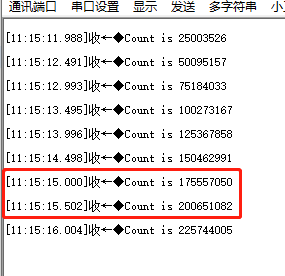
图3 串口打印计数值打印出的计数值中,相邻两个计数值之差为25M,是由于设置定时器频率为50M,每延时500ms计数值增加25M。3. 延时型定时器在config配置脚本中选择hwtimer delay延时型定时器测试如图4所示。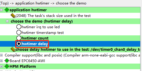 图4 计数型定时器例程保存后重新Build工程,编译好后运行的是demo_hwtimer_count.c的代码,例程关键代码如下:
aw_local void* __task_handle (void *arg){ int i; int fd; aw_err_t ret; aw_timespec_t timespec; aw_timestamp_t start_timestamp, stop_timestamp; aw_timestamp_freq_t timestamp_freq; uint64_t delay_ns, diff; uint32_t ns_numerator = 1000000000;
timestamp_freq = aw_timestamp_freq_get(); while (0 == (timestamp_freq % 10)) { timestamp_freq /= 10; ns_numerator /= 10;}
fd = aw_open(CONFIG_DEMO_HWTIMER_DELAY_DEV_NAME, AW_O_RDWR, 0); if (fd < 0) { aw_kprintf("hwtimer open failed:%d \n\r", fd); while(1); }
delay_ns = 2001000; for (i = 0; i < 100; i++) { timespec.tv_sec = delay_ns / 1000000000u; timespec.tv_nsec = (uint32_t)(delay_ns % 1000000000u);
start_timestamp = aw_timestamp_get(); ret = aw_hwtimer_delay(fd, ×pec); if (ret !=AW_OK) { aw_kprintf("hwtimer delay failed:%d \n\r", ret); } aw_barrier(); stop_timestamp = aw_timestamp_get();
stop_timestamp -= start_timestamp; diff = stop_timestamp; diff *= ns_numerator; diff /= timestamp_freq;
diff = diff - delay_ns; aw_kprintf( "hwtimer_delay delay = %u,diff = %u ns\n", (uint32_t)delay_ns, (uint32_t)diff); delay_ns += 100000; } aw_close(fd); return 0;}
上述代码中在延时开始前使用aw_timestamp_get接口记录时间戳,使用aw_hwtimer_delay接口进行延时,延时结束后记录结束时间戳,用两个时间戳的差值通过换算,用于对比延时不同时间下与timestamp相比的误差,并在串口中打印,打印后增加延时时间,再次循环,串口打印结果如下图所示。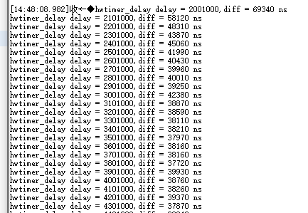 图5 串口打印结果因外设接口调用时代码执行需要时间以及晶振等硬件会导致误差,分析例程打印数据可得,延时性定时器的软件开销在同一硬件以及接口下,其误差基本是一致的。4. 捕获型定时器
{SDK}\demos\peripheral\cap路径下为捕获型定时器例程,例程关键代码如下:
/* 单边沿触发*/static void test_cap_single_edge( int fd, int gpio_cap, uint32_t ms, aw_hwtimer_cap_config_t *p_config, int is_rising){ uint64_t cap_val1, cap_val2; aw_err_t ret;
// 制造两次上升沿 mk_edge(gpio_cap, 5); aw_task_delay(ms); mk_edge(gpio_cap, 5);
// 此时应该产生了两次捕获事件 // 把它们读出来 ret = aw_hwtimer_cap_read(fd, &cap_val1, AW_WAIT_FOREVER); if (AW_OK != ret) { aw_kprintf("cap read cap_val1 failed \n"); return; } ret = aw_hwtimer_cap_read(fd, &cap_val2, AW_WAIT_FOREVER); if (AW_OK != ret) { aw_kprintf("cap read cap_val2 failed \n"); return; }
cap_val2 -= cap_val1; cap_val2 *= 1000000; cap_val2 /= p_config->sample_rate;
if (is_rising) { aw_kprintf("two rising edge between %u ms \n", ms + 5); } else { aw_kprintf("two falling edge between %u ms \n", ms + 5); } aw_kprintf("two capture events between %llu us \n", cap_val2);}
static void demo_cap_base(int gpio_cap){ int fd; aw_err_t ret; aw_hwtimer_cap_config_t config;
// 使得测试GPIO输出为0 aw_gpio_set(gpio_cap, 0);
fd = aw_open(CONFIG_DEMO_HWTIMER_CAP_DEV_NAME, AW_O_RDWR, 0); if (fd < 0) { aw_kprintf("cap open failed!\n"); return; }
// 获取捕获定时器的配置 ret = aw_hwtimer_cap_config_get(fd, &config); if (ret != AW_OK) { aw_kprintf("cap config get failed...\r\n"); aw_close(fd); return ; }
#if CONFIG_SINGLE_EDGE int is_rising; // 配置为上升沿触发捕获 config.cap_edge_flags = AW_CAPTURE_RISING_EDGE; is_rising = 1; ret = aw_hwtimer_cap_config_set(fd, &config); if (ret != AW_OK) { aw_kprintf("cap config set failed...\r\n"); aw_close(fd); return ; }
ret = aw_hwtimer_cap_start(fd); if (ret != AW_OK) { aw_kprintf("cap start failed...\r\n"); aw_close(fd); return ; } test_cap_single_edge(fd, gpio_cap, 20, &config, is_rising);#endif
aw_close(fd);}
在CAP 例程中默认使用的是timer5_chan0,这个通道对应的引脚是PF08,可以通过查看工程下timer5_chan0 对应的.h文件得知所使用的引脚的编号为168,通过查看hpm_pin.h头文件可知编号168对应的引脚为PF08 如下图所示。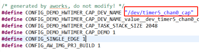 图6 默认通道
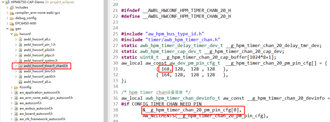 图7 对应引脚编号
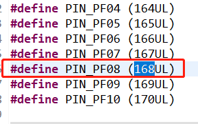
图8 对应引脚本实验中还用到了PF09 这个引脚,用于产生捕获事件,PF09 和 PF08 这两个引脚在开发板上并没有引出来,不利于这次实验,需要修改这两个引脚。 图9 捕获产生引脚参考{SDK} platforms\platform-hpm-aworks-lp\boards\EPC6450-AWI\dts 下的pins.dts 引脚描述文件,找到timer4_chan1 如图10所示,timer4_chan1 使用的引脚是PE25, 对应着开发板排针 UTX1 丝印的位置。
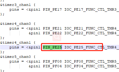 图10 捕获产生引脚打开配置界面将timer5_chan0 修改为timer4_chan1 如图11所示,修改后点击保存,重新build工程。
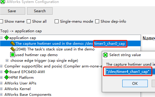 图11 配置界面将CAP_GPIO 对应的引脚改为PIN_PE24,对应着开发板排针 URX1 丝印的位置,如图12所示。
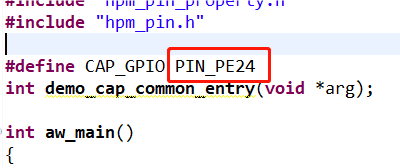
图12 CAP引脚将 PE25 , PE24 这两个引脚,也就是排针上 URX1 和 UTX1 短接。
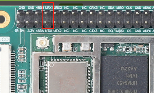
图13 引脚位置上诉代码中使用aw_hwtimer_cap_config_get接口获取捕获定时器的配置信息,配置AW_CAPTURE_RISING_EDGE单通道模式后使用aw_hwtimer_cap_config_set接口配置捕获定时器。使用aw_hwtimer_cap_start接口启动定时器。在test_cap_single_edge函数中调用mk_edge函数制造两次上升沿,使用aw_hwtimer_cap_read接口读取这两次事件捕获到的计数值,计算出差值后在串口上显示。在test_cap_single_edge函数中使用mk_edge函数中控制CAP_GPIO引脚输出高电平后延时5ms再输出低电平。延时20ms后再次调用mk_edge函数,因此两次上升沿事件间隔应为25ms。串口打印结果如下图所示。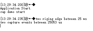 图14 串口打印结果
至此,所有类型的硬件定时器样例均已展示完毕,在软件应用设计中可根据实际需求选取不同类型的定时器进行使用。更多其他类型外设的用法介绍,请关注后续同系列推文~
-
AWorksLP 样例详解(MR6750)——双核调试2023-09-23 1429
-
AWorksLP 样例详解(MR6750)——双核烧录2023-09-21 1562
-
【产品应用】AWorksLP例程介绍(MR6450)—— SD卡2023-05-10 1566
-
EPC6450-AWI工控板搭载MR6450核心板,强势来袭!2023-02-23 1953
-
【产品应用】AWorksLP 样例详解(MR6450)—— HWTimer2023-02-01 1448
-
【产品应用】AWorksLP 样例详解(MR6450)——PWM(单通道)2023-01-04 1217
-
【产品应用】AWorksLP 样例详解(MR6450)——UART2022-12-23 1583
-
【产品应用】AWorksLP样例详解(MR6450)-- GPIO2022-12-16 1457
-
【产品应用】AWorksLP SDK快速入门(MR6450)——开箱体验2022-12-09 1324
-
【深度解析】MR6450系列RISC-V核心板究竟有哪些过人之处?2022-12-05 1558
全部0条评论

快来发表一下你的评论吧 !
