

 为什么MISRA要求你不要使用位域-本文告诉你真相
描述
为什么MISRA要求你不要使用位域-本文告诉你真相 (qq.com)
一.前言
做过嵌入式开发的一般会看到一条编程规范:”不要使用位域”,一般都是知其然不其所以然,了解的多一点的可能知道位域是实现相关不具备可移植性,那么继续追问哪些行为是实现相关哪些行为导致移植性问题? 或者还有人知道,存储布局,对齐等行为是实现相关会导致不可移植性。如果再追问位域产生的汇编代码是什么样的,怎么进行读-修改-写操作的?知道这些内容的就更加少之又少了。 读写肯定不能读指定位数,只能字节,或者16位,32位这种,那么编译器到底读写用什么宽度? 这时基本大部分人都不知道了。
知其然知其所以然,尤其是嵌入式开发和硬件结合比较紧密,所以一定要了解细节,我们这一篇从一个问题引出然后去分析查找原因,只有遇到问题然后去分析解决它才会有更深刻的映像。
二.问题分析过程
问题是驱动程序中一个寄存器的某个位域修改,导致其他位域的值被修改了。
关键代码如下,
1.typedef union nfc_ena_union {
2. uint32_t w;
3. struct {
4. /* spi enable, once the spi trans is completed, this bit will be cleared by HW automaticlly */
5. uint32_t nfc_ena:1; // [0]
6. uint32_t reserved_0:3; // [1,3]
7. /* sw request to use dp */
8. uint32_t nfc_dp_req:1; // [4]
9. uint32_t reserved_1:3; // [5,7]
10. /* due to delay in receiving data, nfc delay one beat to rx */
11. uint32_t nfc_rx_delay_en:1; // [8]
12. uint32_t reserved_2:7; // [9,15]
13. /* spi trans data length, unit is byte,once the spi trans is completed, this bit will be cleared by HW automaticlly */
14. uint32_t nfc_data_len:16; // [16,31]
15. } _b;
16.} nfc_ena_u;
1./**
2. * fn int nfc_set_datalen(uint8_t id, uint16_t len)
3. * param[in] id port id
4. * param[in] len data len
5. * retval 0 ok
6. * retval <0 param err
7. *
8.*/
9.NFC_INLINE int nfc_set_datalen(uint8_t id, uint16_t len)
10.{
11. if(id >= HW_NFC_PORT_MAX)
12. {
13. return -1;
14. }
15. nfc_base[id]->nfc_ena._b.nfc_data_len = len;
16. return 0;
17.}
执行之前该寄存器值为0x00020100
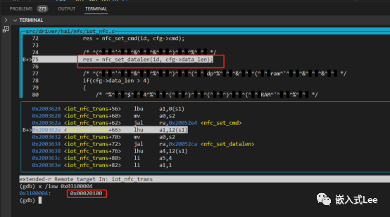
nfc_base[id]->nfc_ena._b.nfc_data_len = len
汇编代码被优化为了写高16位
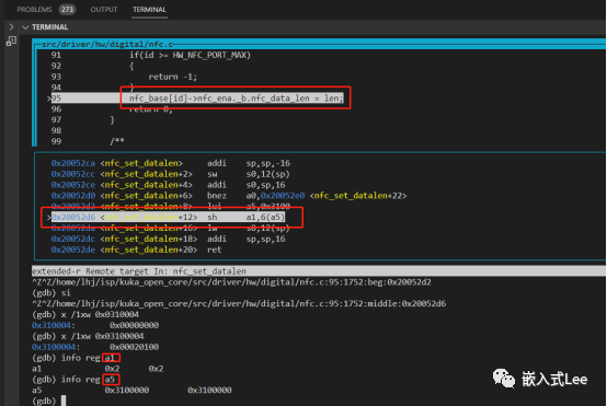
执行完后寄存器低16位变为了0
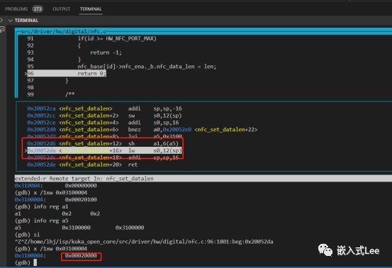
这是因为寄存器硬件上只支持32位的写操作,所以写高16位导致低16位清零了,这是硬件决定的。
二.验证
一般想到的就是优化相关,加volatile等,我们分别验证下。
3.1不使能编译器优化
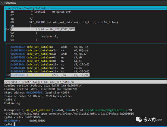
编译器优化选项改为”-O0”
代码不变
依然会按照16位访问,导致低16位被清掉。
所以可以看到这个和编译器行为有关,编译器显然不是根据优化等级决定位域的操作宽度,这里而是根据位域的宽度刚好是16位对齐,所以优化为了16位操作指令。
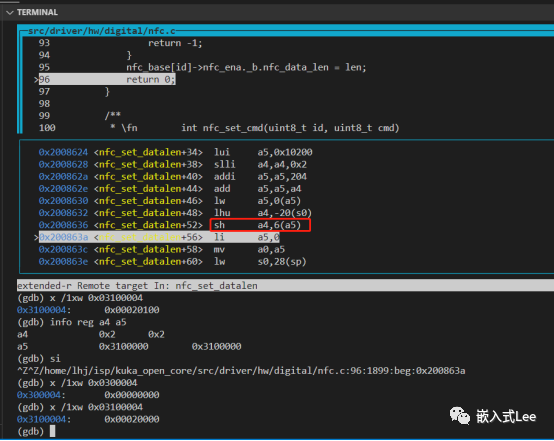
3.2使用volatile避免编译器优化
#ifndef __IOM
#define __IOM volatile
#endif
所有uint32_t替换为__IOM uint32_t
还是一样的
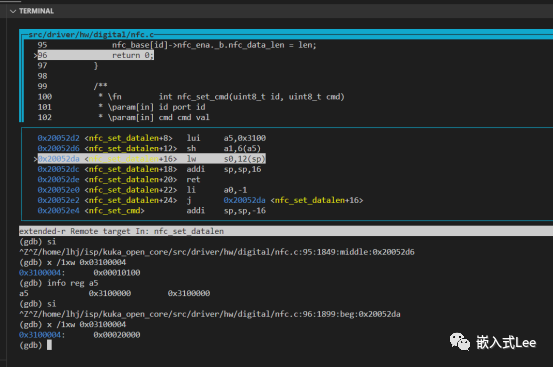
显然汇编代码的访问宽度也不受volatile影响。
3.3为什么指定了uint32_t和volatile还会优化。
问题来了为什么告诉了编译器是uint32_t和volatile,为什么其还要一意孤行,要优化为16位访问指令呢,答案就是因为是标准没有规定,这是编译器实现行为决定的,所以编译器设计者决定的(当然也会有一些现实考虑的),可能不同编译器行为不同,这里以GCC为例。
GCC编译器文档中可以找到答案
GCC的文档可以看到如下内容,也给出了最好是不使用位域的原因


另外也介绍了位域哪些行为也是编译器实现相关的,所以嵌入式可移植性考虑不要使用位域
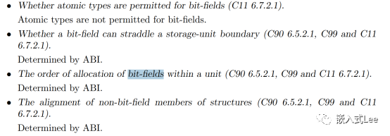
那么有没有办法指定编译按照一定大小访问呢,GCC有编译选项可以控制见下一节。
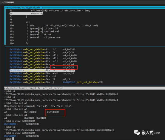
3.4使用编译器选项-fstrict-volatile-bitfields
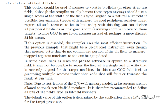
可以看到改为了sw指令,按照32位进行了操作
四.一些厂家做法
如下可见
4.1CMSIS
core_cmxx.h中定义
CMSIS中进行了定义,寄存器个别使用位域
1./* IO definitions (access restrictions to peripheral registers) */
2./**
3.    defgroup CMSIS_glob_defs CMSIS Global Defines
4.
5.    <  strong  >IO Type Qualifiers<  /strong  > are used
6.    li to specify the access to peripheral variables.
7.    li for automatic generation of peripheral register debug information.
8.*/
9.#ifdef __cplusplus
10.  #define   __I     volatile             /*!<   Defines 'read only' permissions */
11.#else
12.  #define   __I     volatile const       /*!<   Defines 'read only' permissions */
13.#endif
14.#define     __O     volatile             /*!<   Defines 'write only' permissions */
15.#define     __IO    volatile             /*!<   Defines 'read / write' permissions */
16.
17./* following defines should be used for structure members */
18.#define     __IM     volatile const      /*! Defines 'read only' structure member permissions */
19.#define     __OM     volatile            /*! Defines 'write only' structure member permissions */
20.#define     __IOM    volatile            /*! Defines 'read / write' structure member permissions */

1.
/**
2.  brief  Structure type to access the Instrumentation Trace Macrocell Register (ITM).
3. */
4.typedef struct
5.{
6.  __OM  union
7.  {
8.    __OM  uint8_t    u8;                 /*!<   Offset: 0x000 ( /W)  ITM Stimulus Port 8-bit */
9.    __OM  uint16_t   u16;                /*!<   Offset: 0x000 ( /W)  ITM Stimulus Port 16-bit */
10.    __OM  uint32_t   u32;                /*!<   Offset: 0x000 ( /W)  ITM Stimulus Port 32-bit */
11.  }  PORT [32U];                         /*!<   Offset: 0x000 ( /W)  ITM Stimulus Port Registers */
12.        uint32_t RESERVED0[864U];
13.  __IOM uint32_t TER;                    /*!<   Offset: 0xE00 (R/W)  ITM Trace Enable Register */
14.        uint32_t RESERVED1[15U];
15.  __IOM uint32_t TPR;                    /*!<   Offset: 0xE40 (R/W)  ITM Trace Privilege Register */
16.        uint32_t RESERVED2[15U];
17.  __IOM uint32_t TCR;                    /*!<   Offset: 0xE80 (R/W)  ITM Trace Control Register */
18.        uint32_t RESERVED3[29U];
19.  __OM  uint32_t IWR;                    /*!<   Offset: 0xEF8 ( /W)  ITM Integration Write Register */
20.  __IM  uint32_t IRR;                    /*!<   Offset: 0xEFC (R/ )  ITM Integration Read Register */
21.  __IOM uint32_t IMCR;                   /*!<   Offset: 0xF00 (R/W)  ITM Integration Mode Control Register */
22.        uint32_t RESERVED4[43U];
23.  __OM  uint32_t LAR;                    /*!<   Offset: 0xFB0 ( /W)  ITM Lock Access Register */
24.  __IM  uint32_t LSR;                    /*!<   Offset: 0xFB4 (R/ )  ITM Lock Status Register */
25.        uint32_t RESERVED5[6U];
26.  __IM  uint32_t PID4;                   /*!<   Offset: 0xFD0 (R/ )  ITM Peripheral Identification Register #4 */
27.  __IM  uint32_t PID5;                   /*!<   Offset: 0xFD4 (R/ )  ITM Peripheral Identification Register #5 */
28.  __IM  uint32_t PID6;                   /*!<   Offset: 0xFD8 (R/ )  ITM Peripheral Identification Register #6 */
29.  __IM  uint32_t PID7;                   /*!<   Offset: 0xFDC (R/ )  ITM Peripheral Identification Register #7 */
30.  __IM  uint32_t PID0;                   /*!<   Offset: 0xFE0 (R/ )  ITM Peripheral Identification Register #0 */
31.  __IM  uint32_t PID1;                   /*!<   Offset: 0xFE4 (R/ )  ITM Peripheral Identification Register #1 */
32.  __IM  uint32_t PID2;                   /*!<   Offset: 0xFE8 (R/ )  ITM Peripheral Identification Register #2 */
33.  __IM  uint32_t PID3;                   /*!<   Offset: 0xFEC (R/ )  ITM Peripheral Identification Register #3 */
34.  __IM  uint32_t CID0;                   /*!<   Offset: 0xFF0 (R/ )  ITM Component  Identification Register #0 */
35.  __IM  uint32_t CID1;                   /*!<   Offset: 0xFF4 (R/ )  ITM Component  Identification Register #1 */
36.  __IM  uint32_t CID2;                   /*!<   Offset: 0xFF8 (R/ )  ITM Component  Identification Register #2 */
37.  __IM  uint32_t CID3;                   /*!<   Offset: 0xFFC (R/ )  ITM Component  Identification Register #3 */
38.} ITM_Type;

1./**
2.  brief  Union type to access the Application Program Status Register (APSR).
3. */
4.typedef union
5.{
6.  struct
7.  {
8.    uint32_t _reserved0:27;              /*!<   bit:  0..26  Reserved */
9.    uint32_t Q:1;                        /*!<   bit:     27  Saturation condition flag */
10.    uint32_t V:1;                        /*!<   bit:     28  Overflow condition code flag */
11.    uint32_t C:1;                        /*!<   bit:     29  Carry condition code flag */
12.    uint32_t Z:1;                        /*!<   bit:     30  Zero condition code flag */
13.    uint32_t N:1;                        /*!<   bit:     31  Negative condition code flag */
14.  } b;                                   /*!<   Structure used for bit  access */
15.  uint32_t w;                            /*!<   Type      used for word access */
16.} APSR_Type;
4.2ST
1./**
2.  * @brief Universal Serial Bus Full Speed Device
3.  */
4.
5.typedef struct
6.{
7.  __IO uint16_t EP0R;                 /*!<   USB Endpoint 0 register,                   Address offset: 0x00 */
8.  __IO uint16_t RESERVED0;            /*!<   Reserved */
9.  __IO uint16_t EP1R;                 /*!<   USB Endpoint 1 register,                   Address offset: 0x04 */
10.  __IO uint16_t RESERVED1;            /*!<   Reserved */
11.  __IO uint16_t EP2R;                 /*!<   USB Endpoint 2 register,                   Address offset: 0x08 */
12.  __IO uint16_t RESERVED2;            /*!<   Reserved */
13.  __IO uint16_t EP3R;                 /*!<   USB Endpoint 3 register,                   Address offset: 0x0C */
14.  __IO uint16_t RESERVED3;            /*!<   Reserved */
15.  __IO uint16_t EP4R;                 /*!<   USB Endpoint 4 register,                   Address offset: 0x10 */
16.  __IO uint16_t RESERVED4;            /*!<   Reserved */
17.  __IO uint16_t EP5R;                 /*!<   USB Endpoint 5 register,                   Address offset: 0x14 */
18.  __IO uint16_t RESERVED5;            /*!<   Reserved */
19.  __IO uint16_t EP6R;                 /*!<   USB Endpoint 6 register,                   Address offset: 0x18 */
20.  __IO uint16_t RESERVED6;            /*!<   Reserved */
21.  __IO uint16_t EP7R;                 /*!<   USB Endpoint 7 register,                   Address offset: 0x1C */
22.  __IO uint16_t RESERVED7[17];        /*!<   Reserved */
23.  __IO uint16_t CNTR;                 /*!<   Control register,                          Address offset: 0x40 */
24.  __IO uint16_t RESERVED8;            /*!<   Reserved */
25.  __IO uint16_t ISTR;                 /*!<   Interrupt status register,                 Address offset: 0x44 */
26.  __IO uint16_t RESERVED9;            /*!<   Reserved */
27.  __IO uint16_t FNR;                  /*!<   Frame number register,                     Address offset: 0x48 */
28.  __IO uint16_t RESERVEDA;            /*!<   Reserved */
29.  __IO uint16_t DADDR;                /*!<   Device address register,                   Address offset: 0x4C */
30.  __IO uint16_t RESERVEDB;            /*!<   Reserved */
31.  __IO uint16_t BTABLE;               /*!<   Buffer Table address register,             Address offset: 0x50 */
32.  __IO uint16_t RESERVEDC;            /*!<   Reserved */
33.} USB_TypeDef;


1./** @defgroup USBD_SCSI_Exported_TypesDefinitions
2.  * @{
3.  */
4.
5.typedef struct _SENSE_ITEM
6.{
7.  char Skey;
8.  union
9.  {
10.    struct _ASCs
11.    {
12.      char ASC;
13.      char ASCQ;
14.    } b;
15.    uint8_t ASC;
16.    char *pData;
17.  } w;
18.} USBD_SCSI_SenseTypeDef;
4.3瑞萨
__I,__O__ROM也是core_cmxx.h中定义,大量使用位域
1. #ifndef __IM                              /*!<   Fallback for older CMSIS versions                                         */
2.  #define __IM     __I
3. #endif
4. #ifndef __OM                              /*!<   Fallback for older CMSIS versions                                         */
5.  #define __OM     __O
6. #endif
7. #ifndef __IOM                             /*!<   Fallback for older CMSIS versions                                         */
8.  #define __IOM    __IO
9. #endif

1./**
2. * @brief R_BUS_CSa [CSa] (CS Registers)
3. */
4.typedef struct
5.{
6.    __IM uint16_t RESERVED;
7.
8.    union
9.    {
10.        __IOM uint16_t MOD;            /*!<   (@ 0x00000002) Mode Register                                              */
11.
12.        struct
13.        {
14.            __IOM uint16_t WRMOD : 1;  /*!<   [0..0] Write Access Mode Select                                           */
15.            uint16_t             : 2;
16.            __IOM uint16_t EWENB : 1;  /*!<   [3..3] External Wait Enable                                               */
17.            uint16_t             : 4;
18.            __IOM uint16_t PRENB : 1;  /*!<   [8..8] Page Read Access Enable                                            */
19.            __IOM uint16_t PWENB : 1;  /*!<   [9..9] Page Write Access Enable                                           */
20.            uint16_t             : 5;
21.            __IOM uint16_t PRMOD : 1;  /*!<   [15..15] Page Read Access Mode Select                                     */
22.        } MOD_b;
23.    };
24.
25.    union
26.    {
27.        __IOM uint32_t WCR1;             /*!<   (@ 0x00000004) Wait Control Register 1                                    */
28.
29.        struct
30.        {
31.            __IOM uint32_t CSPWWAIT : 3; /*!<   [2..0] Page Write Cycle Wait SelectNOTE: The CSPWWAIT value
32.                                          *   is valid only when the PWENB bit in CSnMOD is set to 1.                   */
33.            uint32_t                : 5;
34.            __IOM uint32_t CSPRWAIT : 3; /*!<   [10..8] Page Read Cycle Wait SelectNOTE: The CSPRWAIT value
35.                                          *   is valid only when the PRENB bit in CSnMOD is set to 1.                   */
36.            uint32_t               : 5;
37.            __IOM uint32_t CSWWAIT : 5;  /*!<   [20..16] Normal Write Cycle Wait Select                                   */
38.            uint32_t               : 3;
39.            __IOM uint32_t CSRWAIT : 5;  /*!<   [28..24] Normal Read Cycle Wait Select                                    */
40.            uint32_t               : 3;
41.        } WCR1_b;
42.    };
43.
44.    union
45.    {
46.        __IOM uint32_t WCR2;           /*!<   (@ 0x00000008) Wait Control Register 2                                    */
47.
48.        struct
49.        {
50.            __IOM uint32_t CSROFF : 3; /*!<   [2..0] Read-Access CS Extension Cycle Select                              */
51.            uint32_t              : 1;
52.            __IOM uint32_t CSWOFF : 3; /*!<   [6..4] Write-Access CS Extension Cycle Select                             */
53.            uint32_t              : 1;
54.            __IOM uint32_t WDOFF  : 3; /*!<   [10..8] Write Data Output Extension Cycle Select                          */
55.            uint32_t              : 1;
56.            __IOM uint32_t AWAIT  : 2; /*!<   [13..12] CS Assert Wait Select                                            */
57.            uint32_t              : 2;
58.            __IOM uint32_t RDON   : 3; /*!<   [18..16] RD Assert Wait Select                                            */
59.            uint32_t              : 1;
60.            __IOM uint32_t WRON   : 3; /*!<   [22..20] WR Assert Wait Select                                            */
61.            uint32_t              : 1;
62.            __IOM uint32_t WDON   : 3; /*!<   [26..24] Write Data Output Wait Select                                    */
63.            uint32_t              : 1;
64.            __IOM uint32_t CSON   : 3; /*!<   [30..28] CS Assert Wait Select                                            */
65.            uint32_t              : 1;
66.        } WCR2_b;
67.    };
68.    __IM uint32_t RESERVED1;
69.} R_BUS_CSa_Type;                      /*!<   Size = 16 (0x10)                                                          */
五.总结
结论就是正如很多嵌入式编程规范所描述的(比如MISRA),一般不建议使用位域,因为涉及到位域的访问,存储等行为都是实现定义的,不具备可移植性。
嵌入式领域寄存器的定义也最好不要使用位域,到寄存器级别以寄存器操作为单位即可,每个寄存器都要使用__IM,__OM,__IOM描述。
如果一定要使用位域可以使用-fstrict-volatile-bitfields选项,使用GCC测试可以保证按照固定指定大小访问,但是不保证其他编译器也支持该选项,最好能不使用就不使用位域。
审核编辑 黄宇
-
服务器ups运行时间,图文告诉你关于UPS电源的一些基础知识2021-11-08 788
-
MISRA C编程规范标准有什么规则要求?2021-04-19 1971
-
一文告诉你单相电机运转无力该如何检测2020-12-14 2601
-
智慧城市该如何建设 本文告诉你答案2019-05-29 1525
-
怎么放置洗衣机最好 本文告诉你答案2019-02-15 1303
-
2018的量子计算是怎么跟AI一起两开花的 本文告诉你答案2019-01-15 1101
-
怎么分辨机器人种类 本文告诉你答案2019-01-14 5508
-
智能音箱究竟有哪些用处?本文告诉你答案!2018-09-20 2769
-
如何区分FPGA与CPLD?本文告诉你答案!2018-09-04 2786
-
什么是分层架构的依据与原则?本文告诉你答案!2018-07-27 8018
-
你所不知道的关于iPhone7的几个真相,看完让所有人震惊!2017-02-23 3597
全部0条评论

快来发表一下你的评论吧 !

