

基于STM32+SHT30设计的环境温度与湿度检测系统(IIC模拟时序)
描述
一、项目功能介绍
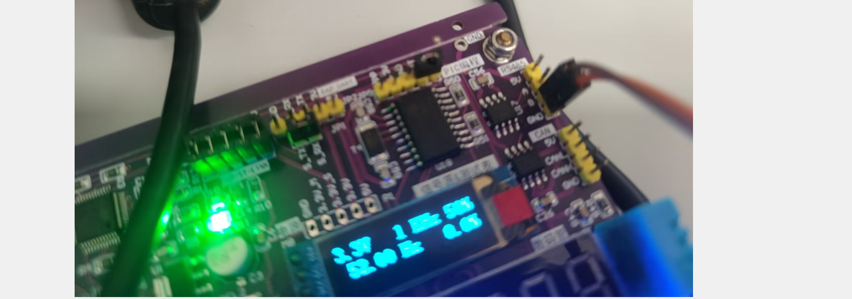
当前介绍基于STM32F103ZCT6芯片设计的环境温度与湿度检测系统设计过程。当前系统通过SHT30温湿度传感器采集环境温度和湿度数据,并通过模拟IIC时序协议将数据传输到STM32芯片上。然后,STM32芯片通过处理这些数据并将它们显示在0.91寸OLED显示屏上,以便用户能够方便地观察环境温度和湿度的变化情况。
系统的主控芯片采用了STM32F103ZCT6,这是一款高性能的32位ARM Cortex-M3微控制器,具有丰富的外设和存储器资源,可满足各种应用的需求。温湿度检测传感器采用了SHT30,这是一款高精度的数字式温湿度传感器,具有快速响应、低功耗、高可靠性等特点。
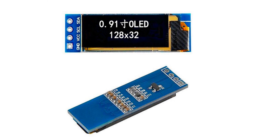
为了实现数据的显示,系统采用了0.91寸OLED显示屏,驱动芯片是SSD1306,接口是IIC协议。OLED显示屏也是通过模拟IIC时序进行驱动,这种方式具有简单、可靠、低功耗等优点。
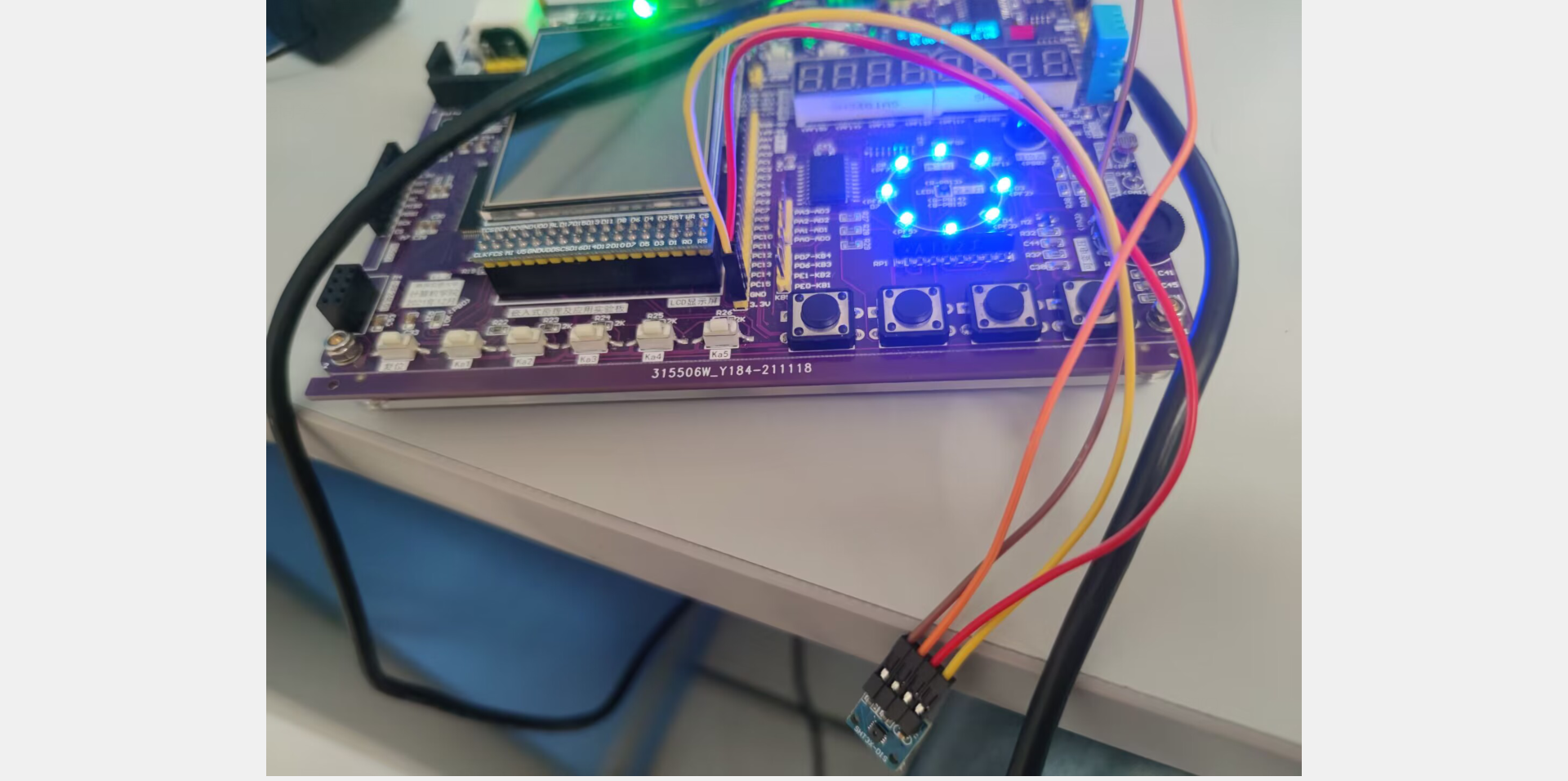
(1)开发板连接SHT30实物图
(2)OLED显示屏


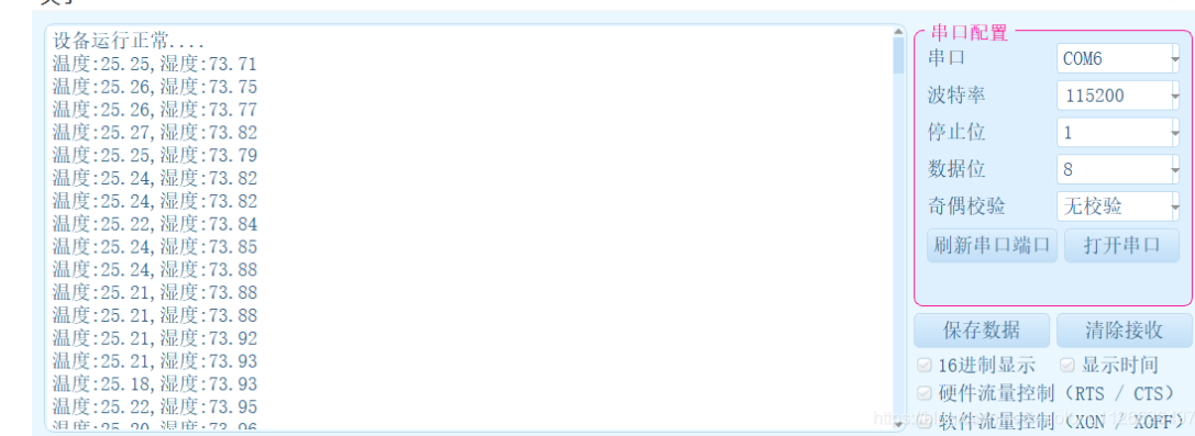
(3)测量的温度湿度串口打印
二、设计思路
2.1 系统硬件设计
主控芯片采用STM32F103ZCT6,该芯片具有72MHz主频,具有丰富的外设资源,包括多个定时器、多个串口、多个I2C接口等。温湿度传感器采用IIC接口的SHT30,该传感器具有高精度、低功耗、数字输出等特点,可提供温度和湿度数据。OLED显示屏采用0.91寸OLED显示屏,驱动芯片是SSD1306,接口也是是IIC协议。
2.2 系统软件设计
系统软件设计采用STM32CubeMX和Keil MDK-ARM工具进行开发。
实现步骤:
(1)使用STM32CubeMX进行芯片引脚配置和初始化代码生成。
(2)编写SHT30温湿度传感器的IIC通信驱动程序。
(3)编写SSD1306 OLED显示屏的IIC通信驱动程序。
(4)编写温湿度检测程序,通过SHT30传感器读取温度和湿度数据,并将数据显示在OLED显示屏上。
(5)编写主程序,将以上各个程序整合在一起,并进行系统初始化和数据处理。
2.3 系统实现
(1)系统硬件实现
系统硬件实现包括主控板、SHT30传感器模块和OLED显示屏模块。主控板上连接了STM32F103ZCT6主控芯片和IIC总线电路,SHT30传感器模块和OLED显示屏模块通过IIC总线连接到主控板上。
(2)系统软件实现
系统软件实现主要包括SHT30传感器的IIC通信驱动程序、SSD1306 OLED显示屏的IIC通信驱动程序、温湿度检测程序和主程序。其中,SHT30传感器的IIC通信驱动程序和SSD1306 OLED显示屏的IIC通信驱动程序都是基于STM32的硬件IIC接口实现的,温湿度检测程序通过SHT30传感器读取温度和湿度数据,并将数据显示在OLED显示屏上。主程序将以上各个程序整合在一起,并进行系统初始化和数据处理。
三、代码实现
3.1 主程序代码
以下是基于STM32设计的环境温度与湿度检测系统的主函数main.c的代码实现:
#include "stm32f10x.h"
#include "systick.h"
#include "sht30.h"
#include "i2c.h"
#include "oled.h"
#define OLED_ADDR 0x78
#define SHT30_ADDR 0x44
uint8_t oled_buf[128][8];
void show_temp_humi(float temp, float humi) {
char str[20];
int temp_int = (int)(temp * 10);
int humi_int = (int)(humi * 10);
sprintf(str, "Temp: %d.%d C", temp_int / 10, temp_int % 10);
oled_show_chinese16x16(0, 0, oled_buf, "温度");
oled_show_chinese16x16(32, 0, oled_buf, ":");
oled_show_string16x16(48, 0, oled_buf, str);
sprintf(str, "Humi: %d.%d %%", humi_int / 10, humi_int % 10);
oled_show_chinese16x16(0, 2, oled_buf, "湿度");
oled_show_chinese16x16(32, 2, oled_buf, ":");
oled_show_string16x16(48, 2, oled_buf, str);
oled_refresh(0, 7, oled_buf);
}
int main(void)
{
RCC_APB2PeriphClockCmd(RCC_APB2Periph_GPIOC, ENABLE);
i2c_init();
systick_init(72);
sht30_init(SHT30_ADDR);
oled_init();
while(1)
{
float temp, humi;
sht30_read_temp_humi(&temp, &humi);
show_temp_humi(temp, humi);
delay_ms(1000);
}
}