

大型网络部署综合配置案例分享
通信网络
描述
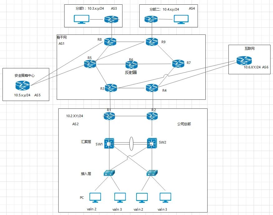
组网需求
公司总部 用户希望在存在冗余备份链路的同时消除网络中的环路,在一条上行链路断开的时候,流量能切换到另外一条上行链路转发,还能合理利用网络带宽。 骨干网 七台路由设备底层均使用OSPF,设备之间使用BGP,路径丰富、可靠性高; R6作为BGP的反射器,帮R5,R6分摊骨干网中控制层的压力; 安全策略中心 所有数据都需引入安全策略中心;对流量的的策略以及清洗; 互联网 与互联网之间使用NAT; 分部1和分部2 可与总部正常通信,并且可以连接到互联网;
配置思路
公司总部
在处于环形网络中的交换设备上配置MSTP基本功能
配置保护功能,实现对设备或链路的保护。
配置设备的二层转发功能。
配置各设备端口IP地址及路由协议,使各设备间网络层连通。
在Sw1和Sw2上创建VRRP备份组1和VRRP备份组2,在备份组1中,配置Sw1为Master设备,Sw2为Backup设备;在备份组2中,配置Sw2为Master设备,Sw1为Backup设备,实现流量的负载均衡。
骨干网
在MPLS骨干网上(R3-R9)配置OSPF,实现骨干网互通。
R6作为BGP反射器,R3,R4,R8,R9做为反射器客户端;
配置BGP-VPNv4路由反射功能
骨干所有路由设备运行MPLS,LDP模式;
分别在各PE设备(R3/4/8/9)上配置VPN实例,将CE接入;
将R10,R11,建立EBGP邻居并且将路由宣告进来
安全策略中心
做4个VRF(BGP MPLS VPN 的设计),另外为R8创建4个VRF
配置步骤
公司总部
1、配置LACP模式的链路聚合 创建Eth-Trunk,配置Eth-Trunk为LACP模式,实现链路聚合功能 在SwitchA上创建Eth-Trunk1并配置为LACP模式。SwitchB的配置与SwitchA类似,不再赘述
[SwitchA] interface eth-trunk 1
[SwitchA-Eth-Trunk1] mode lacp
[SwitchA-Eth-Trunk1] quit
配置SwitchA上的成员接口加入Eth-Trunk。SwitchB的配置与SwitchA类似,不再赘述
  [SwitchA] interface gigabitethernet 0/0/1
  [SwitchA-GigabitEthernet0/0/1] eth-trunk 1
  [SwitchA-GigabitEthernet0/0/1] quit
  [SwitchA] interface gigabitethernet 0/0/2
  [SwitchA-GigabitEthernet0/0/2] eth-trunk 1
  [SwitchA-GigabitEthernet0/0/2] quit
在SwitchA上配置系统优先级为100,使其成为LACP主动端
[SwitchA] lacp priority 1002、配置处于环网中的设备的二层转发功能 在交换设备SwitchA、SwitchB、SwitchC、SwitchD上创建VLAN2~3,这里以SwitchA为例。 # 在SwitchA上创建VLAN2~3
[sw1]vlan batch 2 3
将交换设备上接入终端中的端口加入VLAN
#将SwitchC端口GE0/0/3和G0/0/4加入VLAN。SwitchD的配置与SwitchC类似,详见配置文件
[sw1]interface GigabitEthernet 0/0/3
[sw1-GigabitEthernet0/0/3]port link-type access
[sw1-GigabitEthernet0/0/3]port default vlan 2
[sw1-GigabitEthernet0/0/3]quit
[sw1]interface GigabitEthernet 0/0/4
[sw1-GigabitEthernet0/0/3]port link-type access
[sw1-GigabitEthernet0/0/3]port default vlan 3
将交换设备上接入环路中的端口加入VLAN
# 将SwitchC端口GE0/0/1,G0/0/2加入VLAN。witchD的配置与SwitchC类似,详见配置文件。
[SwitchA] interface gigabitethernet 0/0/1
[SwitchA-GigabitEthernet0/0/1] port link-type trunk
[SwitchA-GigabitEthernet0/0/1] port trunk allow-pass vlan 2 to 3
[SwitchA-GigabitEthernet0/0/1] quit
[SwitchA] interface gigabitethernet 0/0/2
[SwitchA-GigabitEthernet0/0/1] port link-type trunk
[SwitchA-GigabitEthernet0/0/1] port trunk allow-pass vlan 2 to 3
[SwitchA-GigabitEthernet0/0/1] quit
# 将SwitchA端口GE0/0/3,G0/0/4,Eth-Trunk1加入VLAN。witchA的配置与SwitchD类似,详见配置文件
[SwitchA]interface Eth-Trunk 1
[SwitchA-Eth-Trunk1]port link-type trunk
[SwitchA-Eth-Trunk1]port trunk allow-pass vlan 2 to 3
[SwitchA-Eth-Trunk1]quit
[SwitchA]interface GigabitEthernet 0/0/3
[SwitchA-GigabitEthernet0/0/4] port link-type trunk
[SwitchA-GigabitEthernet0/0/4] port trunk allow-pass vlan 2 to 3
[SwitchA-GigabitEthernet0/0/4] quit
[SwitchA]interface GigabitEthernet 0/0/4
[SwitchA-GigabitEthernet0/0/4] port link-type trunk
[SwitchA-GigabitEthernet0/0/4] port trunk allow-pass vlan 2 to 3
[SwitchA-GigabitEthernet0/0/4] quit
3、配置MSTP基本功能
配置SwitchA、SwitchB、SwitchC、SwitchC到域名为HW的域内,创建实例MSTI1和实例MSTI2,SwitchB/C/D的配置与SwitchA类似,详见配置文件
[SwitchA]stp region-configuration
[SwitchA-mst-region]region-name HW
[SwitchA-mst-region]revision-level 1
[SwitchA-mst-region]instance 1 vlan 2
[SwitchA-mst-region]instance 2 vlan 3
[SwitchA-mst-region] quit
在域HW内,配置MSTI1与MSTI2的根桥与备份根桥
配置MSTI1的根桥与备份根桥
# 配置SwitchA为MSTI1的根桥
[SwitchA] stp instance 1 root primary
# 配置SwitchB为MSTI1的备份根桥。
[SwitchB] stp instance 1 root secondary
配置MSTI2的根桥与备份根桥
# 配置SwitchB为MSTI2的根桥
[SwitchB] stp instance 2 root primary
# 配置SwitchA为MSTI2的备份根桥
[SwitchA] stp instance 2 root secondary
配置实例MSTI1和MSTI2中将要被阻塞端口的路径开销值大于缺省值
# 配置SwitchA的端口路径开销计算方法为华为计算方法。SwitchB/CD的配置与SwitchA类似,详见配置文件
[SwitchA] stp pathcost-standard legacy
SwitchC将端口GE0/0/1在实例MSTI2中的路径开销值配置为20000,SwitchD将端口GE0/0/1在实例MSTI1中的路径开销值配置为20000。SwitchD的配置与SwitchC类似,详见配置文件
[SwitchC]interface GigabitEthernet 0/0/1
[SwitchC-GigabitEthernet0/0/1]stp instance 2 cost 2000
[SwitchC-GigabitEthernet0/0/1] quit
使能MSTP,实现破除环路
设备全局使能MSTP,SwitchB/CD的配置与SwitchA类似,详见配置文件
[SwitchA]stp enable
[SwitchA]stp mode mstp
将与Host相连的端口设置为边缘端口
# 配置SwitchC端口GE0/0/4和GE0/0/3为边缘端口。SwitchD的配置与SwitchC类似,详见配置文件
[SwitchC]interface GigabitEthernet 0/0/3
[SwitchC-GigabitEthernet0/0/3]stp edged-port enable
[SwitchC-GigabitEthernet0/0/3]quit
[SwitchC]interface GigabitEthernet 0/0/4
[SwitchC-GigabitEthernet0/0/4]stp edged-port enable
[SwitchC-GigabitEthernet0/0/4]quit
(可选)全局配置SwitchC的BPDU保护功能。SwitchB/CD的配置与SwitchA类似,详见配置文件
[SwitchC] stp bpdu-protection
将与Router相连的端口设置为边缘端口,SwitchB的配置与SwitchA类似,详见配置文件
[SwitchA]interface GigabitEthernet 0/0/5
[SwitchA-GigabitEthernet0/0/5]stp edged-port enable
配置保护功能,如在各实例的根桥设备的指定端口配置根保护功能
# 在SwitchA端口GE0/0/3上启动根保护。SwitchB类似
[SwitchA] interface gigabitethernet 0/0/3
[SwitchA-GigabitEthernet0/0/1] stp root-protection
[SwitchA-GigabitEthernet0/0/1] quit
4.配置VRRP基本功能
配置设备间的网络互连**
# 配置设备各端口的IP地址,以SwitchA为例。SwitchB的配置与SwitchA类似,详见配置文件。
[SwitchA]interface Vlanif 2
[SwitchA-Vlanif2]ip add 10.2.2.100 24
[SwitchA-Vlanif2]quit
[SwitchA]interface Vlanif 3
[SwitchA-Vlanif3]ip add 10.2.3.100 24
[SwitchA-Vlanif3]quit
[SwitchA]interface Vlanif 101
[SwitchA-Vlanif101]ip add 10.2.101.1 24
[SwitchA-Vlanif101] quit
# 配置SwitchA、SwitchB和路由器间采用OSPF协议进行互连。以SwitchA为例,SwitchB的配置与SwitchA类似,详见配置文件。
[SwitchB]interface GigabitEthernet 0/0/05
[SwitchB-GigabitEthernet0/0/5]port link-type access
[SwitchB-GigabitEthernet0/0/5]port default vlan 202
[SwitchB-GigabitEthernet0/0/5]quit
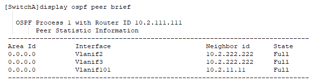
[SwitchA]ospf 1 router-id 10.2.111.111
[SwitchA-ospf-1-area-0.0.0.0]network 10.2.101.1 0.0.0.0
[SwitchA-ospf-1-area-0.0.0.0]network 10.2.2.100 0.0.0.0
[SwitchA-ospf-1-area-0.0.0.0]network 10.2.3.100 0.0.0.0
查看结果(以SwitchA为例)
配置VRRP备份组
# 在SwitchA和SwitchB上创建VRRP备份组1,配置SwitchA的优先级为120,抢占延时为10秒,作为Master设备;SwitchB的优先级为缺省值,作为Backup设备。
interface Vlanif2
 ip address 10.2.2.100 255.255.255.0
 vrrp vrid 1 virtual-ip 10.2.2.254
 vrrp vrid 1 priority 120
 vrrp vrid 1 preempt-mode timer delay 10
 vrrp vrid 1 track interface GigabitEthernet0/0/5 reduced 30
 quit
interface Vlanif3
 ip address 10.2.3.100 255.255.255.0
 vrrp vrid 2 virtual-ip 10.2.3.254
interface Vlanif3
ip address 10.2.3.101 255.255.255.0
vrrp vrid 1 virtual-ip 10.2.3.254
vrrp vrid 1 priority 120
vrrp vrid 1 preempt-mode timer delay 10
vrrp vrid 1 track interface GigabitEthernet0/0/5 reduced 30
quit
interface Vlanif2
ip address 10.2.2.101 255.255.255.0
vrrp vrid 1 virtual-ip 10.2.2.254
骨干网
P、PE之间配置OSPF,实现骨干网的IP连通性。
PE、P上配置MPLS基本能力和MPLS LDP,建立MPLS LSP公网隧道,传输VPN数据。
PE1和PE2之间配置MP-IBGP,交换VPN路由信息。
P、PE之间配置OSPF,实现骨干网的IP连通性。
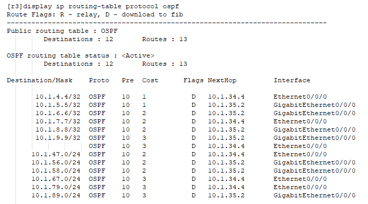
配置OSFP(R3为例)
[r3-ospf-1-area-0.0.0.0]network 10.1.0.0 0.0.255.255
PE、P上配置MPLS基本能力和MPLS LDP,建立MPLS LSP公网隧道,传输VPN数据。配置MPLS LDP(R3为例)
[r3]mpls lsr-id 10.1.3.3
  Info: Mpls starting, please wait... OK!

  [r3]mpls
  [r3-mpls]quit
  [r3]mpls ldp
  [r3-mpls-ldp]quit
  [r3]interface G0/0/0
  [r3-GigabitEthernet0/0/0]mpls
  [r3-GigabitEthernet0/0/0]mpls  ldp
  [r3-GigabitEthernet0/0/0]quit

  [r3]interface Eth0/0/0
  [r3-Ethernet0/0/0]mpls
  [r3-Ethernet0/0/0]mpls ldp
  [r3-Ethernet0/0/0]quit
在PE设备上配置VPN实例,将CE接入PE
以R1为例子
  ip vpn-instance AS2
   ipv4-family
    route-distinguisher 3:3
    vpn-target 3:3 export-extcommunity
    vpn-target 12:2 12:22 import-extcommunity


  [r3]interface Ethernet0/0/1
  [r3-Ethernet0/0/1] ip binding vpn-instance AS2
R8 作为中转路由器将数据汇聚向AS5的安全策略中心
 ip vpn-instance AS3
   ipv4-family
    route-distinguisher 8:8
    vpn-target 8:8 export-extcommunity
    vpn-target 12:3 12:33 import-extcommunity


  ip vpn-instance toAS2
   ipv4-family
    route-distinguisher 12:2
    vpn-target 12:2 export-extcommunity
    vpn-target 3:3 4:4 import-extcommunity

  ip vpn-instance toAS3
   ipv4-family
    route-distinguisher 12:3
    vpn-target 12:3 export-extcommunity
    vpn-target 8:8 import-extcommunity

  ip vpn-instance toAS4
   ipv4-family
    route-distinguisher 12:4
    vpn-target 12:4 export-extcommunity
    vpn-target 9:9 import-extcommunity

  ip vpn-instance toAS6
   ipv4-family
    route-distinguisher 12:6
    vpn-target 12:6 export-extcommunity
    vpn-target 3:6 4:6 import-extcommunity
创建四个子接口用来接收Vpnv4路由
以g0/0/1.2为例子
  interface GigabitEthernet0/0/1.2
   dot1q termination vid 2
   ip binding vpn-instance toAS2
   ip address 10.5.2.1 255.255.255.0
   arp broadcast enable
在PE与CE之间建立EBGP对等体关系,引入VPN路由
# 配置CE1。CE2、CE3和CE4的配置与CE1类似,详见配置文件。
[R4]
  ipv4-family vpn-instance AS2
    peer 10.2.24.1 as-number 2
  ------------------------------------------
  bgp 2
   peer 10.2.1.1 as-number 2
   peer 10.2.1.1 connect-interface LoopBack0
   peer 10.2.24.2 as-number 1
   #
   ipv4-family unicast
    undo synchronization
    import-route ospf 1
    peer 10.2.1.1 enable
    peer 10.2.1.1 next-hop-local
    peer 10.2.24.2 enable
在PE之间建立MP-IBGP对等体关系
R6为反射器
 bgp 1
   group IBGP internal
   peer IBGP connect-interface LoopBack0
   peer 10.1.3.3 as-number 1
   peer 10.1.3.3 group IBGP
   peer 10.1.4.4 as-number 1
   peer 10.1.4.4 group IBGP
   peer 10.1.8.8 as-number 1
   peer 10.1.8.8 group IBGP
   peer 10.1.9.9 as-number 1
   peer 10.1.9.9 group IBGP
   #
   ipv4-family unicast
    undo synchronization
    peer IBGP enable
    peer IBGP reflect-client
    peer 10.1.3.3 enable
    peer 10.1.3.3 group IBGP
    peer 10.1.4.4 enable
    peer 10.1.4.4 group IBGP
    peer 10.1.8.8 enable
    peer 10.1.8.8 group IBGP
    peer 10.1.9.9 enable
    peer 10.1.9.9 group IBGP
   #
   ipv4-family vpnv4
    undo policy vpn-target
    peer IBGP enable
    peer IBGP reflect-client
    peer IBGP advertise-community
    peer 10.1.3.3 enable
    peer 10.1.3.3 group IBGP
    peer 10.1.4.4 enable
    peer 10.1.4.4 group IBGP
    peer 10.1.8.8 enable
    peer 10.1.8.8 group IBGP
    peer 10.1.9.9 enable
    peer 10.1.9.9 group IBGP
R3,R4,R8,R9为反射器客户端(配置相同)
  bgp 1
   peer 10.1.6.6 as-number 1
   peer 10.1.6.6 connect-interface LoopBack0
   peer 10.1.6.6 advertise-community
编辑:黄飞
-
浅析综合能耗监测系统在大型园区的应用2024-09-18 1129
-
浅谈基于多能源的大型智慧园区安科瑞综合能耗监测系统研究与应用2023-06-14 1962
-
智能配电系统在大型综合建筑中的应用2023-04-12 1127
-
综合能效管理系统在大型数据中心的应用2022-02-08 934
-
如何使用stm32cube.ai部署神经网络?2021-10-11 4827
-
为什么安装对大型物联网部署如此重要?2021-03-26 2319
-
网络综合布线的特点2020-06-13 1696
-
基于LoRaWAN协议的网络网络部署2019-07-26 2383
-
华为天线在LTE网络部署的应用2019-07-15 2754
-
eRelay成功解决Small Cell的传输部署问题2019-07-12 2414
-
TETRA的网络配置2019-06-14 1317
-
基于大型装备维修计划综合评估2017-12-19 955
-
电网络分析与综合2012-09-14 1994
全部0条评论

快来发表一下你的评论吧 !
