

为什么时钟树上要用clock inverter(min pulse width check)?
电子说
描述
Min pulse width定义
最小脉冲宽度检查可确保时钟信号的宽度足够宽,以便采集到正确的数据,保证设计功能。即为了获得稳定的输出,需要确保时钟信号宽度至少达到某个“最小宽度”。比如lib中就对寄存器Flipflop的CLK pin有min pulse width的check。
- High pulse width
If you need a formal definition of the term, it is the interval between the rising edge of the signal crossing 50% of VDD and the falling edge of the signal crossing 50% of VDD.
- Low pulse width
If talking in terms of low signals, it is the the interval between falling edge of the signal crossing 50% of VDD and the rising edge of signal crossing 50% of VDD.
以下图为例,一个时钟信号CLK,经过六级普通buffer(各自的rise time和fall time是不相同的)到达一个寄存器的CK 端。我们来计算下high pulse width,low pulse width以及判断是否存在min pulse width违例(uncertainty:80ps Reg ck pin requirement min pulse width:0.420ns)。
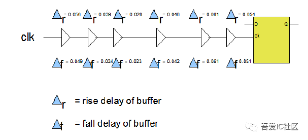
High pulse width = 0.5 + (0.049-0.056) + (0.034 -0.039) + (0.023-0.026) + (0.042-0.046) + (0.061 – 0.061) + (0.051-0.054) = 0.478ns
Low Pulse width = 0.5 + (0.056 – 0.049) + (0.038 – 0.034) + (0.026 – 0.023) + (0.046 – 0.042) + (0.061 – 0.061) + (0.054 – 0.051) = 0.522ns
high pulse width = 0.478-0.080 = 0.398ns (小于0.420ns)
因此, 存在min pulse width violation 。
Min pulse width检查方式
- Liberty文件
Liberty文件中对寄存器的CLK pin和reset pin均有一个默认的min pulse width check值。在STA分析时工具会自动载入进行check。如图1所示,index_1为input transition。
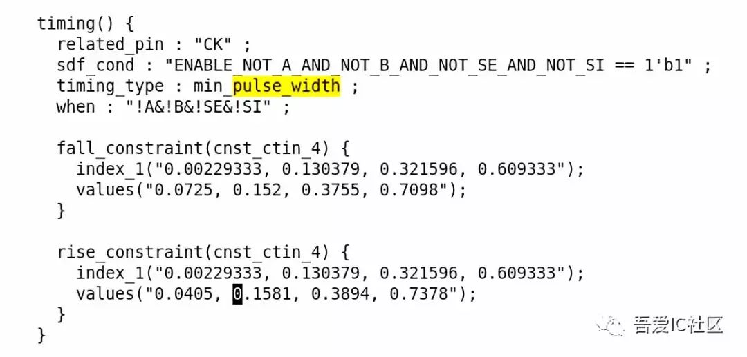
图1 lib中min_pulse_width属性定义
- SDC约束
除了采用lib文件中默认的min pulse width值check外,我们还可以通过如下SDC命令来设置特殊的约束条件。
set_min_pulse_width -high 2 [get_clocks clk]
set_min_pulse_width -low 1 [get_clocks clk]
理想clock buffer/inverter的特性
- Equal rise and fall times
- Less delay variations with PVT and OCV
- Clock buffer能够驱动较长的net以及更多的fanout
普通buffer如何导致pulse width violation?
图2显示了Wp = 100nm&Wn = 100nm的Buffer电路的示意图。β比率(PMOS的宽度与NMOS的宽度的比率)由于NMOS的迁移率高于PMOS,因此上升时间大于下降时间。这个结论是根据电流公式得出的,不懂的请移步模拟电路查阅。
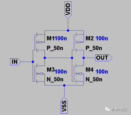
图2 Unbalanced Buffer电路原理图
这里的每个buffer都需要更多的时间来充电(相比放电过程)。输入为占空比为50%的周期为4ns的脉冲信号。当时钟信号通过buffer chain传播时,脉冲宽度如下图4所示减少相当多。最后一个buffer的输出具有相同的周期,但占空比发生了变化。在最坏的情况下,这种情况可能会小于设计所需的脉冲宽度(最小脉冲宽度)。

图3 Unbalanced Buffer Chain
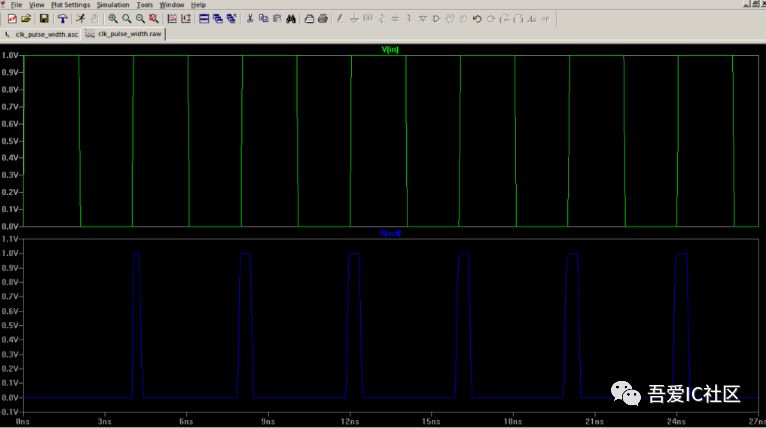
图4 pulse width reduction
Balanced buffers have equal rise and fall time
为了使得buffer的上升和下降时间一致,PMOS的宽度应该约为NMOS的两倍(具体倍数关系取决于工艺)。Balance buffer电路结构图如图5所示。图6为一堆balanced buffer级联的buffer chain的输出波形。从输出波形看到,当我们在clock path上使用这种balanced buffer,输出时钟信号周期未发生变化且占空比仍然为1:1,即不会出现pulse width violation。
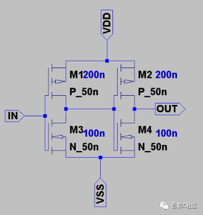
图5 balance buffer电路结构图
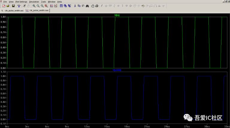
图6 Balanced Buffer Chain 输出波形
unbalanced inverter有没有min pulse width问题?
如果在时钟路径中使用偶数个反相器,一对反相器上升和下降时间会相互补偿,所以脉冲宽度并不会改变。所以反相器输出不会导致脉冲宽度违规。
图7所示为一个反相器的电路结构图。其中Wp = 100nm,Wn = 300nm。根据P管和N管的尺寸,我们得知上升时间比下降时间小得多。
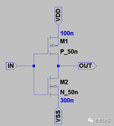
图7 Unbalanced 反相器原理图
图8所示为一个十级反相器级联的电路图。图9为第九级和第十级反相器输出波形图。从图中可以得知,unbalance inverter同样也不会导致min pulse width问题。

图8 unbalanced inverter chain
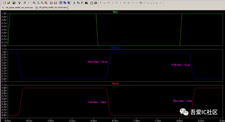
图9 第九级,第十级反相器输出波形图
所以,在做时钟树综合时,我们往往选用clock inverter来长clock tree。
-
时钟子系统中clock驱动实例2023-09-27 1912
-
时序分析概念min pulse width介绍2023-07-03 4904
-
什么是Min Period检查?2023-06-17 3519
-
PULSE WIDTH VHDL程序2016-11-11 498
-
Check Bus width mismatch2016-04-24 8864
-
Pulse Width Modulation2016-03-21 449
-
TMS320x28xx,28xxx_High-Resolution_Pulse_Width_Modulator(HRPWM)Reference_Guide2016-01-19 3047
-
cadence16.6----------Check Bus width mismatch2015-10-30 14222
-
TL1451A,pdf(Dual Pulse-Width-M2010-10-05 988
-
TL598,pdf,(PULSE-WIDTH-MODULAT2010-09-29 822
-
LM5021,off-line pulse width mo2009-09-29 659
-
脉宽调制器工作在不同层次的频率和功耗-Pulse-Width2009-05-03 748
-
TL494 Pulse-Width-Modulation C2008-12-12 758
-
Pulse Width Modulator circuits2008-03-14 2012
全部0条评论

快来发表一下你的评论吧 !

