

Microchip PIC系列8位单片机入门教程(2):点亮LED灯
控制/MCU
1933人已加入
描述
01第一节 配置字
前言:器件选择PIC18F4520
(1)配置字的含义:PIC系列的单片机都有配置字,这是从宏观设置单片机功能的寄存器,我们不需要手动配置。
首先我们新建一个源文件main.c
在包含头文件的前面单击,让光标在前面。
在工具栏中点击Production->set Configutation Bits
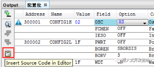
配置好之后点击红色框就将配置的信息插入到main.c 的头文件包含语句的前面了。这个必须在包含头文件的语句之前。
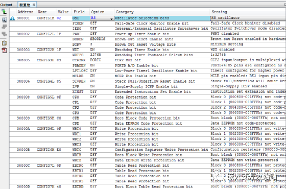
(2)配置字的解释:
// CONFIG1H
#pragma config OSC = HS         // Oscillator Selection bits (HS oscillator)--振荡器选择位(HS振荡器)
#pragma config FCMEN = OFF      // Fail-Safe Clock Monitor Enable bit (Fail-Safe Clock Monitor disabled)--失效保护时钟监视器启用位(失效保护时钟监视器禁用)
#pragma config IESO = OFF       // Internal/External Oscillator Switchover bit (Oscillator Switchover mode disabled)--内部/外部振荡器切换位(振荡器切换模式禁用)


// CONFIG2L
#pragma config PWRT = OFF       // Power-up Timer Enable bit (PWRT disabled)--通电定时器启用位(PWRT禁用)
#pragma config BOREN = SBORDIS  // Brown-out Reset Enable bits (Brown-out Reset enabled in hardware only (SBOREN is disabled))--失电输出复位启用位(仅在硬件中启用失电输出复位(禁用SBOREN))
#pragma config BORV = 3         // Brown Out Reset Voltage bits (Minimum setting)--失电复位电压位(最小设置)


// CONFIG2H
#pragma config WDT = OFF        // Watchdog Timer Enable bit (WDT disabled (control is placed on the SWDTEN bit))
#pragma config WDTPS = 32768    // Watchdog Timer Postscale Select bits (1:32768)--看门狗定时器启用位(WDT禁用(控制置于SWDTEN位))


// CONFIG3H
#pragma config CCP2MX = PORTC   // CCP2 MUX bit (CCP2 input/output is multiplexed with RC1)--看门狗定时器启用位(WDT禁用(控制置于SWDTEN位上))CCP2 MUX位(CCP2输入/输出与RC1多路复用)
#pragma config PBADEN = OFF      // PORTB A/D Enable bit (PORTB< 4:0 >pins are configured as analog input channels on Reset)--端口B A/D启用位(端口B< 4:0 >引脚在复位时配置为模拟输入通道)
#pragma config LPT1OSC = OFF    // Low-Power Timer1 Oscillator Enable bit (Timer1 configured for higher power operation)--端口B A/D启用位(复位时端口B< 4:0 >引脚配置为模拟输入通道)低功率定时器1振荡器启用位(定时器1配置为高功率操作)
#pragma config MCLRE = OFF      // MCLR Pin Enable bit (RE3 input pin enabled; MCLR disabled) ---MCLR引脚启用位(RE3输入引脚启用;MCLR禁用)


// CONFIG4L
#pragma config STVREN = OFF     // Stack Full/Underflow Reset Enable bit (Stack full/underflow will not cause Reset)--堆栈满/下溢复位启用位(堆栈满/下溢不会导致复位)
#pragma config LVP = OFF        // Single-Supply ICSP Enable bit (Single-Supply ICSP disabled)--单电源ICSP启用位(单电源ICSP禁用)
#pragma config XINST = OFF      // Extended Instruction Set Enable bit (Instruction set extension and Indexed Addressing mode disabled (Legacy mode))--扩展指令集启用位(禁用指令集扩展和索引寻址模式(传统模式))


// CONFIG5L
#pragma config CP0 = OFF        // Code Protection bit (Block 0 (000800-001FFFh) not code-protected)--代码保护位(块0(000800-001FFFh)不受代码保护)
#pragma config CP1 = OFF        // Code Protection bit (Block 1 (002000-003FFFh) not code-protected)--代码保护位(块1(002000-003FFFh)不受代码保护)
#pragma config CP2 = OFF        // Code Protection bit (Block 2 (004000-005FFFh) not code-protected)--代码保护位(块2(004000-005FFFh)不受代码保护)
#pragma config CP3 = OFF        // Code Protection bit (Block 3 (006000-007FFFh) not code-protected)--代码保护位(块3(006000-007FFFh)不受代码保护)


// CONFIG5H
#pragma config CPB = OFF        // Boot Block Code Protection bit (Boot block (000000-0007FFh) not code-protected)--引导块代码保护位(引导块(000000-0007FFh)不受代码保护)
#pragma config CPD = OFF        // Data EEPROM Code Protection bit (Data EEPROM not code-protected)--数据EEPROM代码保护位(数据EEPROM不受代码保护)


// CONFIG6L
#pragma config WRT0 = OFF       // Write Protection bit (Block 0 (000800-001FFFh) not write-protected)--写保护位(块0(000800-001FFFh)未写保护)
#pragma config WRT1 = OFF       // Write Protection bit (Block 1 (002000-003FFFh) not write-protected)--写保护位(块1(002000-003FFFh)未写保护)
#pragma config WRT2 = OFF       // Write Protection bit (Block 2 (004000-005FFFh) not write-protected)--写保护位(块2(004000-005FFFh)不写保护)
#pragma config WRT3 = OFF       // Write Protection bit (Block 3 (006000-007FFFh) not write-protected)--写保护位(块3(006000-007FFFh)未写保护)


// CONFIG6H
#pragma config WRTC = OFF       // Configuration Register Write Protection bit (Configuration registers (300000-3000FFh) not write-protected)--配置寄存器写保护位(配置寄存器(300000-3000FFh)不写保护)
#pragma config WRTB = OFF       // Boot Block Write Protection bit (Boot block (000000-0007FFh) not write-protected)--引导块写保护位(引导块(000000-0007FFh)未写保护)
#pragma config WRTD = OFF       // Data EEPROM Write Protection bit (Data EEPROM not write-protected)--数据EEPROM写保护位(数据EEPROM不写保护)


// CONFIG7L
#pragma config EBTR0 = OFF      // Table Read Protection bit (Block 0 (000800-001FFFh) not protected from table reads executed in other blocks)--表读取保护位(块0(000800-001FFFh)不受其他块中执行的表读取的保护)
#pragma config EBTR1 = OFF      // Table Read Protection bit (Block 1 (002000-003FFFh) not protected from table reads executed in other blocks)--表读取保护位(块1(002000-003FFFh)不受其他块中执行的表读取的保护)
#pragma config EBTR2 = OFF      // Table Read Protection bit (Block 2 (004000-005FFFh) not protected from table reads executed in other blocks)--表读取保护位(块2(004000-005FFFh)不受其他块中执行的表读取的保护)
#pragma config EBTR3 = OFF      // Table Read Protection bit (Block 3 (006000-007FFFh) not protected from table reads executed in other blocks)--表读取保护位(块3(006000-007FFFh)不受在其他块中执行的表读取的保护)


// CONFIG7H
#pragma config EBTRB = OFF      // Boot Block Table Read Protection bit (Boot block (000000-0007FFh) not protected from table reads executed in other blocks)--引导块表读取保护位(引导块(000000-0007FFh)不受在其他块中执行的表读取的保护)


// #pragma config statements should precede project file includes.--pragma config语句应该在project file includes之前
// Use project enums instead of #define for ON and OFF.
我们主要选择配置好时钟、关闭看门狗,其他的默认就可以了。如果在产品中要保护代码段可以根据具体要求设置,使用ADC是要打开PBADED ON;
02第二节 代码编写
我们在main.c 中添加宏:
#define _XTAL_FREQ 40000000 //定义时钟为40MHz
#define LED_PORT_DIR TRISD
#define LED_PORT_DATD LATD
const unsigned char LED[8]={0x01,0x02,0x04,0x08,0x10,0x20,0x40,0x80};
第一个宏是定义时钟的频率,第二是定义led灯的端口方向寄存器,第三个是定义端口的寄存器。
第一个函数:初始化控制LED灯的端口,配置为输出方向,初始值为0;
第四个是变量,实现流水灯的。
void pic18_led_port_init(void)
{
  LED_PORT_DIR=0;   //Setting output direction for LED stream .
  LED_PORT_DATD=0;  // Init LED port data to low voltage.
}
第二个函数是实现流水灯:
void led_stream_show(void)
{
    unsigned char i;
    for(i=0;i< < span="" >8;i++)
    {
        LATD=LED[i];
        __delay_ms(1000);  //延时1s
    }
    LATD=0xFF;
    __delay_ms(1000);
    LATD=0;
    __delay_ms(1000);
}
使用_delayms(1000);这个是系统函数,前面定义了时钟频率,就可以直接使用了。
我们编写main函数看效果:
void main(void)
{
    pic18_led_port_init();
    while(1)
    {
        led_stream_show();
    }
}
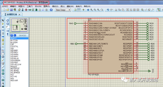
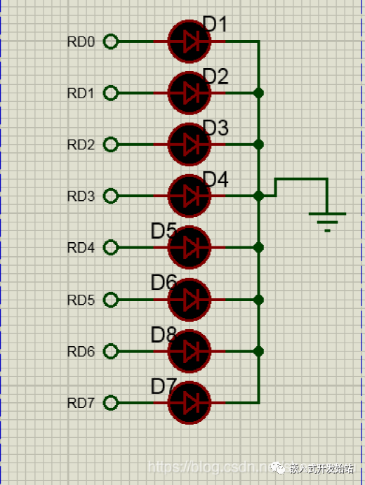
因为手头开发板不在,所以在proteus中PORTD端口安放了8个led灯仿真了下,是可以的。
03总结
LED灯的实现主要使用了单片机的I/O 端口,方向寄存器设置为0,输出,在PORTD端口的数据锁存器写入值就可以控制LED灯的亮灭。
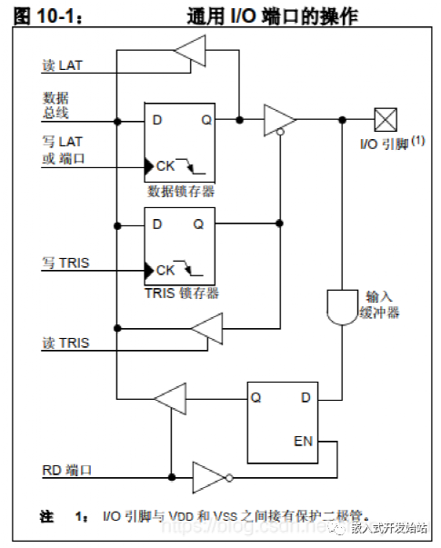
从图中就可以看出,如果要读PORTD端口的值则要使用PORTD寄存器。写使用LATD。再加一点延迟函数,就实现流水灯的效果。
声明:本文内容及配图由入驻作者撰写或者入驻合作网站授权转载。文章观点仅代表作者本人,不代表电子发烧友网立场。文章及其配图仅供工程师学习之用,如有内容侵权或者其他违规问题,请联系本站处理。
举报投诉
-
基于51单片机点亮LED灯2023-07-11 3089
-
单片机入门之点亮LED灯2023-06-26 3508
-
基于单片机点亮LED灯2023-05-24 2889
-
51单片机——点亮一个LED灯2021-11-23 3040
-
单片机零基础入门(1):点亮1个LED灯2021-11-18 1474
-
PIC系列单片机2021-11-16 2944
-
51单片机入门教程(1)——点亮一个LED灯 精选资料推荐2021-07-15 1086
-
如何使用单片机点亮LED灯2019-07-16 3242
-
Microchip扩展通用8位PIC单片机系列2013-05-15 2132
-
Microchip推出全新的8位PIC单片机2011-09-28 7705
-
PIC单片机图解入门教程2011-05-26 2264
-
PIC 8位单片机的分类和特点2010-03-27 2402
-
Microchip推出多款全新8位PIC单片机2010-03-10 1019
-
单片机入门教程2006-03-21 2806
全部0条评论

快来发表一下你的评论吧 !
