

 RA4M2开发(3)----读取ISL29035数据,并在OLED上显示,串口打印
描述
概述
- 首先导入必要的库文件,包括I2C驱动和OLED驱动。
- 在代码中配置I2C接口,并初始化I2C驱动。
- 配置ISL29035传感器,包括配置传感器的工作模式和量程。
- 使用I2C读取ISL29035传感器的数据,并将其存储在变量中。
- 初始化OLED驱动,并在OLED屏幕上显示读取的数据。 请注意,这仅是一个大致的步骤,具体实现可能因硬件和软件环境而异。 对于OLED的配置,可以查看往期的博客。
视频教学
[https://www.bilibili.com/video/BV1wc411g7xU/]
csdn课程
csdn课程更加详细。
[https://edu.csdn.net/course/detail/36131]
样品申请
[https://www.wjx.top/vm/wBbmSFp.aspx#]
硬件准备
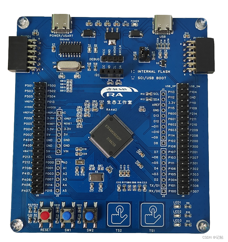
首先需要准备一个开发板,这里我准备的是芯片型号R7FAM2AD3CFP的开发板:
样品申请
[https://www.wjx.top/vm/wBbmSFp.aspx#]
IIC配置
配置RA4M2的I2C接口,使其作为I2C master进行通信。 对于OLED的IIC配置,可以查看往期的博客。 查看ISL29035说明书,最小电路图如下所示。

由于需要读取ISL29035数据,需要使用IIC接口,这里使用PMOD2上的接口(P410和P411)。

点击Stacks->New Stack->Connectivity -> I2C Master(r_sci_i2c)。

查看说明书可以得知,ISL29035的地址为0x44(1000100)。

设置IIC的配置。

R_SCI_I2C_Open()函数原型

R_SCI_I2C_Open()函数为执行IIC初始化,开启配置如下所示。
/* Initialize the I2C module */
        err = R_SCI_I2C_Open(&g_i2c0_ctrl, &g_i2c0_cfg);
        /* Handle any errors. This function should be defined by the user. */
        assert(FSP_SUCCESS == err);
R_SCI_I2C_Write()函数原型

R_SCI_I2C_Write()函数是向IIC设备中写入数据,写入格式如下所示。
err = R_SCI_I2C_Write(&g_i2c0_ctrl, &g_i2c_tx_buffer[0], I2C_BUFFER_SIZE_BYTES, false);
    assert(FSP_SUCCESS == err);
R_SCI_I2C_Read()函数原型

R_SCI_I2C_Read()函数是向IIC设备中读取数据,读取格式如下所示。
err = R_SCI_I2C_Write(&g_i2c0_ctrl, &g_i2c_tx_buffer[0], I2C_BUFFER_SIZE_BYTES, false);
    assert(FSP_SUCCESS == err);
sci_i2c_master_callback()回调函数
对于数据是否发送完毕,可以查看是否获取到I2C_MASTER_EVENT_TX_COMPLETE字段。

/* Callback function */
i2c_master_event_t i2c_event1 = I2C_MASTER_EVENT_ABORTED;
void sci_i2c_master_callback0(i2c_master_callback_args_t *p_args)
{
    /* TODO: add your own code here */
    i2c_event1 = I2C_MASTER_EVENT_ABORTED;
    if (NULL != p_args)
    {
        /* capture callback event for validating the i2c transfer event*/
        i2c_event1 = p_args- >event;
    }
}
ISL29035写数据
对于ISL29035写数据,手册上的操作方式如下所示。 设备地址+操作地址+数据

初始化程序如下所示。
void DigitalLightISL29035_writeRegister( int reg_address, uint8_t val) {

    uint8_t ii[2]={0x00,0x00};
    ii[0] = reg_address;
    ii[1] = val;


    err = R_SCI_I2C_Write(&g_i2c0_ctrl, ii, 0x02, false);
           assert(FSP_SUCCESS == err);
           /* Since there is nothing else to do, block until Callback triggers*/
           //while ((I2C_MASTER_EVENT_TX_COMPLETE != i2c_event) && timeout_ms)
           while ((I2C_MASTER_EVENT_TX_COMPLETE != i2c_event1) && timeout_ms1 >0)
           {
               R_BSP_SoftwareDelay(1U, BSP_DELAY_UNITS_MICROSECONDS);
               timeout_ms1--;
           }
           if (I2C_MASTER_EVENT_ABORTED == i2c_event1)
           {
               __BKPT(0);
           }
           /* Read data back from the I2C slave */
           i2c_event1 = I2C_MASTER_EVENT_ABORTED;
           timeout_ms1           = 100000;


}
ISL29035读数据
对于ISL29035读数据,手册上的操作方式如下所示。 设备地址+操作地址+设备地址+数据读取

读取操作函数如下所示,先发送操作地址,在进行读取。
uint8_t DigitalLightISL29035_readRegister(uint8_t reg_address) {

    uint8_t value;
    err = R_SCI_I2C_Write(&g_i2c0_ctrl, ®_address, 0x01, false);
    assert(FSP_SUCCESS == err);
    /* Since there is nothing else to do, block until Callback triggers*/
    while ((I2C_MASTER_EVENT_TX_COMPLETE != i2c_event1) && timeout_ms1 >0)
    {
        R_BSP_SoftwareDelay(1U, BSP_DELAY_UNITS_MICROSECONDS);
        timeout_ms1--;
        }
    if (I2C_MASTER_EVENT_ABORTED == i2c_event1)
    {
        __BKPT(0);
        }
    /* Read data back from the I2C slave */
    i2c_event1 = I2C_MASTER_EVENT_ABORTED;
    timeout_ms1           = 100000;

    /* Read data from I2C slave */
    err = R_SCI_I2C_Read(&g_i2c0_ctrl, &value, 0x01, false);
    assert(FSP_SUCCESS == err);
    while ((I2C_MASTER_EVENT_RX_COMPLETE != i2c_event1) && timeout_ms1)
    {
        R_BSP_SoftwareDelay(1U, BSP_DELAY_UNITS_MILLISECONDS);
        timeout_ms1--;
    }
    if (I2C_MASTER_EVENT_ABORTED == i2c_event1)
    {
        __BKPT(0);
    }

    i2c_event1 = I2C_MASTER_EVENT_ABORTED;
    timeout_ms1           = 100000;
    return value;
}
ISL29035初始化
- 读取设备ID,查看是否链接上
- 清除标志位
- 确保芯片处于停止模式
- 设置分辨率
- 设置模式,如单次模式 读取设备ID使用0x0F指令,可以判断DEVICE ID BITS (B3-B5),之后需要对BROWNOUT STATUS BIT - BOUT (B7)清0。

初始化的时候需要确保芯片处于停止模式,需要对0x00指令的OPERATION MODE BITS (B5-B7)写入000。

设置分辨率可以通过0x01指令,光照强度有4种模式,1k, 4k, 16k和64k,通过FULL SCALE LUX RANGE (B0-B1)进行设置;ADC分辨率也有4种模式,通过ADC RESOLUTION (B3-B2)进行设置。

设置采样模式,可以通过0x00指令,对OPERATION MODE BITS (B5-B7)写入010。

int DigitalLightISL29035_init(void) {
    uint8_t reg = 0;
    reg=   DigitalLightISL29035_readRegister( CHIP_ID);//CHIP_ID- >0x0f
    //Serial.println(reg, HEX);
    uint8_t chip_id = (reg > > 3) & 0x7;
    if (chip_id != 0x5) {
        return -1;
    }

    //清除BOUT位
    DigitalLightISL29035_writeRegister(CHIP_ID, reg & 0x7f);//CHIP_ID- >0x0f

    //确保芯片处于停止模式
    DigitalLightISL29035_writeRegister( COMMAND_I, 0);//COMMAND_I- >0x00
    //设置分辨率
    DigitalLightISL29035_writeRegister(COMMAND_II, full_scale_lux_range | (integration_time < < 2) );//COMMAND_2- >0x01
    //设置为单次模式
    DigitalLightISL29035_writeRegister( COMMAND_I, OPMODE_ALS_ONCE);//COMMAND_I- >0x00
    return 0;
}
ISL29035读取光照强度
设置采样模式,可以通过0x00指令,对OPERATION MODE BITS (B5-B7)写入010。
不同的ADC精度需要等待的时间不同,16位的等待时间最久,需要105ms。

对于读取数据,可以使用Data Registers (Addresses: 0x02 and 0x03),高位字节通过0x03读取,低位字节通过0x02读取,之后进行组合,就是完整的数据。

读取到原始数据之后,可以通过下面公式计算光照强度。

uint32_t DigitalLightISL29035_readIRLux(void) {
    uint16_t data = 0;
    uint8_t l, h;
    //设置为单次模式
    DigitalLightISL29035_writeRegister( COMMAND_I, OPMODE_ALS_ONCE);
    //等待时间
    if(integration_time==0)
    {
        R_BSP_SoftwareDelay(105, BSP_DELAY_UNITS_MILLISECONDS);
    }
    else if(integration_time==1 || integration_time==2)
    {
        R_BSP_SoftwareDelay(7, BSP_DELAY_UNITS_MILLISECONDS);
    }
    else if(integration_time==3)
    {
        R_BSP_SoftwareDelay(1, BSP_DELAY_UNITS_MILLISECONDS);
    }

    l=DigitalLightISL29035_readRegister(DATA_L);//DATA_L- >0x02
    h=DigitalLightISL29035_readRegister(DATA_H);//DATA_H- >0x03

    data=(h < < 8) | l;

    uint32_t ranges=0;
    if(full_scale_lux_range==0)
        ranges=1000;
    else if(full_scale_lux_range==1)
        ranges=4000;
    else if(full_scale_lux_range==2)
        ranges=16000;
    else if(full_scale_lux_range==3)
        ranges=64000;

    uint32_t adc_count_max=0;
    if(integration_time==0)
        adc_count_max=65536;
    else if(integration_time==1)
        adc_count_max=4096;
    else if(integration_time==2)
        adc_count_max=256;
    else if(integration_time==3)
        adc_count_max=16;
    return ranges * (uint32_t)data /adc_count_max;


}
实现效果
正常显示数据。

同时可以通过串口打印数据。

由于设置光照采样为1K,故只能读取到999。

重新设置光照采样范围为4k,就可以读取0-4K的范围了,具体设置需要考虑使用环境。

主程序
#include "hal_data.h"
#include < stdio.h >
#include "Digital_Light_ISL29035.h"
#include "oled.h"
#include "bmp.h"

FSP_CPP_HEADER
void R_BSP_WarmStart(bsp_warm_start_event_t event);
FSP_CPP_FOOTER


fsp_err_t err = FSP_SUCCESS;
volatile bool uart_send_complete_flag = false;
/* Callback function */
void user_uart_callback(uart_callback_args_t *p_args)
{
    /* TODO: add your own code here */
    if(p_args- >event == UART_EVENT_TX_COMPLETE)
     {
         uart_send_complete_flag = true;
     }
}


#ifdef __GNUC__                                 //串口重定向
    #define PUTCHAR_PROTOTYPE int __io_putchar(int ch)
#else
    #define PUTCHAR_PROTOTYPE int fputc(int ch, FILE *f)
#endif

PUTCHAR_PROTOTYPE
{
        err = R_SCI_UART_Write(&g_uart9_ctrl, (uint8_t *)&ch, 1);
        if(FSP_SUCCESS != err) __BKPT();
        while(uart_send_complete_flag == false){}
        uart_send_complete_flag = false;
        return ch;
}

int _write(int fd,char *pBuffer,int size)
{
    for(int i=0;i< size;i++)
    {
        __io_putchar(*pBuffer++);
    }
    return size;
}

/* Callback function */
i2c_master_event_t i2c_event = I2C_MASTER_EVENT_ABORTED;
void sci_i2c_master_callback(i2c_master_callback_args_t *p_args)
{
    i2c_event = I2C_MASTER_EVENT_ABORTED;
    if (NULL != p_args)
    {
        /* capture callback event for validating the i2c transfer event*/
        i2c_event = p_args- >event;
    }
}


/* Callback function */
i2c_master_event_t i2c_event1 = I2C_MASTER_EVENT_ABORTED;
void sci_i2c_master_callback0(i2c_master_callback_args_t *p_args)
{
    /* TODO: add your own code here */
    i2c_event1 = I2C_MASTER_EVENT_ABORTED;
    if (NULL != p_args)
    {
        /* capture callback event for validating the i2c transfer event*/
        i2c_event1 = p_args- >event;
    }
}


uint32_t  timeout_ms = 100000;
uint32_t  timeout_ms1 = 100000;
uint32_t lux =0;

/*******************************************************************************************************************//**
 * main() is generated by the RA Configuration editor and is used to generate threads if an RTOS is used.  This function
 * is called by main() when no RTOS is used.
 **********************************************************************************************************************/
void hal_entry(void)
{
    /* TODO: add your own code here */


    /* Initialize the I2C module */
    err = R_SCI_I2C_Open(&g_i2c3_ctrl, &g_i2c3_cfg);
    /* Handle any errors. This function should be defined by the user. */
    assert(FSP_SUCCESS == err);


    /* Open the transfer instance with initial configuration. */
        fsp_err_t err = R_SCI_UART_Open(&g_uart9_ctrl, &g_uart9_cfg);
        assert(FSP_SUCCESS == err);

        printf("hello world!n");
        /* Initialize the I2C module */
        err = R_SCI_I2C_Open(&g_i2c0_ctrl, &g_i2c0_cfg);
        /* Handle any errors. This function should be defined by the user. */
        assert(FSP_SUCCESS == err);


        DigitalLightISL29035_init();
        R_BSP_SoftwareDelay(500U, BSP_DELAY_UNITS_MILLISECONDS);
        lux = DigitalLightISL29035_readIRLux();
        printf("lux=%dn",lux);

        OLED_Init();            //初始化OLED
        OLED_Clear()    ;
        OLED_ShowCHinese(0,0,0);//记
        OLED_ShowCHinese(16,0,1);//帖
        OLED_ShowString(0,2,"Lux:",16);
        OLED_ShowNum(32,2,lux,3,16);


        /* Wait for minimum time required between transfers. */
        R_BSP_SoftwareDelay(2, BSP_DELAY_UNITS_SECONDS);

        while(1)
        {

            OLED_Clear()    ;
            OLED_ShowCHinese(0,0,0);//记
            OLED_ShowCHinese(16,0,1);//帖
            OLED_ShowString(0,2,"Lux:",16);
            lux = DigitalLightISL29035_readIRLux();
            if(lux< 10)
                OLED_ShowNum(32,2,lux,1,16);
            else if(lux >=10&&lux< 100)
                OLED_ShowNum(32,2,lux,2,16);
            else if(lux >=100&&lux< 1000)
                OLED_ShowNum(32,2,lux,3,16);
            else if(lux >=1000&&lux< 10000)
                OLED_ShowNum(32,2,lux,4,16);
            printf("lux=%dn",lux);
            R_BSP_SoftwareDelay(1000U, BSP_DELAY_UNITS_MILLISECONDS);

        }
#if BSP_TZ_SECURE_BUILD
    /* Enter non-secure code */
    R_BSP_NonSecureEnter();
#endif
}
Digital_Light_ISL29035.h
/*
 * Digital_Light_ISL29035.h
 *
 *  Created on: 2023年2月1日
 *      Author: a8456
 */

#ifndef DIGITAL_LIGHT_ISL29035_H_
#define DIGITAL_LIGHT_ISL29035_H_
#include "stdint.h"


#define ISL29035_I2C_ADDRESS    0x44   //the 7bits i2c address

#define COMMAND_I               0x00
#define COMMAND_II              0x01
#define DATA_L                  0x02
#define DATA_H                  0x03
#define INT_LT_L                0x04
#define INT_LT_H                0x05
#define INT_HT_L                0x06
#define INT_HT_H                0x07
#define CHIP_ID                 0x0f

#define OPMODE_ALS_ONCE         ((0x1)< < 5)
#define OPMODE_IR_ONCE          ((0x2)< < 5)
#define OPMODE_ALS_CONTI        ((0x5)< < 5)
#define OPMODE_IR_CONTI         ((0x6)< < 5)

#define FULL_SCALE_LUX_RANGE0   1000
#define FULL_SCALE_LUX_RANGE1   4000
#define FULL_SCALE_LUX_RANGE2   16000
#define FULL_SCALE_LUX_RANGE3   64000
#define DEFAULT_LUX_RANGE_INDEX 1       //should be [0,3]

#define INTEGRATION_TIME3       0.0256  //ms, this also configure the ADC to 4bits
#define INTEGRATION_TIME2       0.41  //ms, this also configure the ADC to 8bits
#define INTEGRATION_TIME1       6.5  //ms, this also configure the ADC to 12bits
#define INTEGRATION_TIME0       105  //ms, this also configure the ADC to 16bits
#define DEFAULT_INTEGRATION_TIME_INDEX 1  //should be [0,3]

uint8_t DigitalLightISL29035_readRegister(uint8_t reg_address);
void DigitalLightISL29035_writeRegister( int reg_address, uint8_t val) ;
int DigitalLightISL29035_init(void) ;
uint32_t DigitalLightISL29035_readIRLux(void);

#endif /* DIGITAL_LIGHT_ISL29035_H_ */
审核编辑:汤梓红
-
RA4M2开发(1)----使用串口进行打印2023-07-27 2960
-
RA4M2组数据表2023-07-04 596
-
ISL29035 数据表2023-04-19 125
-
【精品合集】瑞萨RA4M2物联网网关设计挑战赛作品合集2023-03-07 151538
-
【RA4M2设计挑战赛】读取isl29035模块数据2023-02-26 1392
-
【RA4M2设计挑战赛】模拟IIC isl29035驱动2023-02-23 1959
-
【RA4M2设计挑战赛】读取HS3003数据,并在OLED上显示,串口打印2023-02-22 20040
-
【RA4M2设计挑战赛】读取ISL29035数据,并在OLED上显示,串口打印2023-02-14 18746
-
【RA4M2设计挑战赛】3. 硬件IIC读取ISL29035采集光照强度2023-02-11 1762
-
RA4M2 组数据表2023-02-03 637
-
RA4M2数据手册(中英)2022-11-07 798
-
基于RT-Thread+RA6M4的光照监控设备相关资料介绍2022-08-15 1197
-
ISL29035:一款极具超小封装的数字型红外光传感器2018-11-06 2282
全部0条评论

快来发表一下你的评论吧 !
