
FPGA学习笔记:RAM IP核的使用方法
描述
理论学习
我们知道除了只读存储器外还有随机存取存储器,这一篇将介绍另一种 存储类IP核 ——RAM的使用方法。RAM是 随机存取存储器 (Random Access Memory),是一个易失性存储器,断电丢失。RAM工作时可以随时从任何一个指定的地址写入或读出数据。
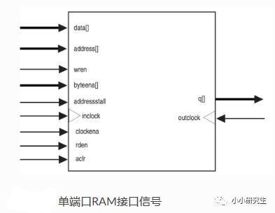
同样的,Altera推出的RAM IP核分为两种类型:单端口RAM和双端口RAM。其中双端口RAM又分为简单双端口RAM(Simple dual port RAM)和真正双端口RAM(True dual port RAM)。对于单端口RAM,读写操作共用一组地址线,读写操作不能同时进行;对于简单双端口RAM,读操作和写操作有专用地址端口(一个读端口和一个写端口),即写端口只能写不能读,而读 端口只能读不能写;对于真正双端口RAM,有两个地址端口用于读写操作(两个读/写端口),即两个端口都可以进行读写。


RAM IP核配置
一端口的配置几乎和rom没有区别


勾选上创建“aclr”异步复位信号以及是否创建“rden”读使能信号


简单双端口和真正双端口都是在双端口中去配置的,配置的选项的定义和ROM中一样


真正双端口的配置除了选择真正双端口以外,其他的选项和简单双端口的配置一样

设计规划
按下按键1时往RAM地址0255里写入数据0255;按下按键2时读取RAM内的数据,从地址0开始每隔0.2s地址加1往下进行读取;再次按下按键1时停止读取重新写入数据0~255;再次按下按键2时从头开始读取数据

一共有5个模块:按键消抖模块(使用两次),RAM控制模块,IP核,数码管动态显示模块,顶层模块。实际需要做的是RAM控制模块
编写代码
ROM控制模块

RAM的写时序为:当RAM写时钟上升沿采到写使能为高时,就能将该上升沿采到的数据写入该上升沿采到的地址中。
RAM的读时序为:当RAM读时钟上升沿采到读使能为高时,就能读出该上升沿采到的地址中的数据。若是我们配置IP核时 没有生成RAM读使能 ,那么RAM就能直接读出读时钟上升沿采到的地址中的数据。
按键1按下key_flag1拉高一个时钟,写使能有效,地址从0-255,写数据从0-255,写完后写使能释放;按键2按下时key_flag2拉高一个时钟,读使能有效,cnt_200开始计数,每0.2s读取一次给出地址对应的数据。读完255后回到0继续读取,如此循环,直至再次按下按键1,则读使能释放,再次写入数据。
若写使能有效时,按下按键2并不能读数据。写使能有效时再次按下按键1,地址归0重新写入。
module ram_ctrl
(
input wire sys_clk ,
input wire sys_rst_n ,
input wire key1_flag ,
input wire key2_flag ,
output reg wr_en , //写RAM使能,高电平有效
output reg rd_en , //读RAM使能,高电平有效
 output reg [7:0] addr , //读写RAM地址
 output wire [7:0] wr_data //写RAM数据
 );


 //parameter define
 parameter CNT_MAX = 9_999_999; //0.2s计数器最大值


 //reg define
 reg [23:0] cnt_200ms ; //0.2s计数器


 //让写入的数据等于地址数,即写入数据0~255
 assign wr_data = (wr_en == 1'b1) ? addr : 8'd0;


 //wr_en:产生写RAM使能信号
 always@(posedge sys_clk or negedge sys_rst_n)
 if(sys_rst_n == 1'b0)
 wr_en <= 1'b0;
 else if(addr == 8'd255)
 wr_en <= 1'b0;
 else if(key1_flag == 1'b1)
 wr_en <= 1'b1;


 //rd_en:产生读RAM使能信号
 always@(posedge sys_clk or negedge sys_rst_n)
 if(sys_rst_n == 1'b0)
 rd_en <= 1'b0;
 else if(key2_flag == 1'b1 && wr_en == 1'b0)
 rd_en <= 1'b1;
 else if(key1_flag == 1'b1)
 rd_en <= 1'b0;
 else
 rd_en <= rd_en;


 //0.2s循环计数
 always@(posedge sys_clk or negedge sys_rst_n)
 if(sys_rst_n == 1'b0)
 cnt_200ms <= 24'd0;
 else if(cnt_200ms == CNT_MAX || key2_flag == 1'b1)
 cnt_200ms <= 24'd0;
 else if(rd_en == 1'b1)
 cnt_200ms <= cnt_200ms + 1'b1;


 //写使能有效时,
 always@(posedge sys_clk or negedge sys_rst_n)
 if(sys_rst_n == 1'b0)
 addr <= 8'd0;
 else if((addr == 8'd255 && cnt_200ms == CNT_MAX) ||
 (addr == 8'd255 && wr_en == 1'b1) ||
 (key2_flag == 1'b1) || (key1_flag == 1'b1))
 addr <= 8'd0;
 else if((wr_en == 1'b1) || (rd_en == 1'b1 && cnt_200ms == CNT_MAX))
 addr <= addr + 1'b1;


 endmodule
输入信号有时钟,复位,按键1标志信号,按键2标志信号,输出信号有写使能,读使能,读写地址,写数据
参数定义:计数器的最大计数值是9_999_999
写入数据和地址一致,用三目运算符进行选择,如果写使能有效,写数据就是地址,无效写数据就为0
写使能信号:复位有效时写使能归0;地址为255时写使能归0;按键1标志信号拉高时写使能拉高
读使能信号:复位有效时读使能归0;按键1标志信号拉高时读使能归0(即使在读数据,写使能有效时优先写入数据);按键2标志信号拉高且写使能无效时,读信号拉高(写数据优先,写使能无效时才能读数据);其他情况读使能保持
计数cnt_200ms:复位有效时计数器归0;计数到最大值且按键2标志信号拉高时计数器归0;读使能有效时计数器+1
地址信号:复位有效时地址归0;地址为255且计数到最大值或者地址为255且写使能有效或者按键2标志信号拉高或者按键1标志信号拉高时地址归0;写使能有效或读使能为1且计数到最大值时地址+1
**顶层模块
**
module ram
(
input wire sys_clk ,
input wire sys_rst_n ,
input wire [1:0] key ,
output wire stcp ,
output wire shcp ,
output wire ds
 );


 //wire define
 wire wr_en ;
 wire rd_en ;
 wire [7:0] addr ;
 wire [7:0] wr_data ;
 wire [7:0] rd_data ;
 wire key1_flag ;
 wire key2_flag ;


 ram_ctrl ram_ctrl_inst
 (
 .sys_clk (sys_clk ),
 .sys_rst_n (sys_rst_n ),
 .key1_flag (key1_flag ),
 .key2_flag (key2_flag ),
 .wr_en (wr_en ),
 .rd_en (rd_en ),
 .addr (addr ),
 .wr_data (wr_data )
 );


 key_filter key1_filter_inst
 (
 .sys_clk (sys_clk ),
 .sys_rst_n (sys_rst_n ),
 .key_in (key[0] ),
 .key_flag (key1_flag )
 );


 key_filter key2_filter_inst
 (
 .sys_clk (sys_clk ),
 .sys_rst_n (sys_rst_n ),
 .key_in (key[1] ),
 .key_flag (key2_flag )
 );


 seg_595_dynamic seg_595_dynamic_inst
 (
 .sys_clk (sys_clk ),
 .sys_rst_n (sys_rst_n ),
 .data ({12'd0,rd_data} ),
 .seg_en (1'b1 ), //数码管使能信号,高电平有效
 .stcp (stcp ), //输出数据存储寄时钟
 .shcp (shcp ), //移位寄存器的时钟输入
 .ds (ds ), //串行数据输入
 );


 //---------------rom_256x8_inst--------------
 ram_256x8 ram_256x8_inst
 (
 .aclr (~sys_rst_n ), //异步清零信号
 .address (addr ), //读写地址线
 .clock (sys_clk ), //使用系统时钟作为读写时钟
 .data (wr_data ), //输入写入RAM的数据
 .rden (rd_en ), //读RAM使能
 .wren (wr_en ), //写RAM使能
 .q (rd_data ) //输出读RAM数据
 );
 endmodule
实际上是几个模块的实例化:ram控制模块,按键消抖模块要实例化两次,第一个模块的key_in对应着key[0],flag对应key1_flag,第二个模块的key_in对应着key[1],flag对应key2_flag,数码管动态显示模块将使能信号置1,ram的ip核模块的异步清零信号置为复位信号取反,其他信号名和控制模块中定义的信号名对接

Testbench
`timescale 1ns/1ns
module tb_ram();


//wire define
wire stcp;
wire shcp;
wire ds ;
//reg define
reg sys_clk ;
reg sys_rst_n ;
reg [1:0] key ;


//对sys_clk,sys_rst赋初值,并模拟按键抖动
initial
begin
sys_clk = 1'b1 ;
sys_rst_n <= 1'b0 ;
key <= 2'b11;
#200 sys_rst_n <= 1'b1 ;
//按下按键key[1]
#2000 key[1] <= 1'b0;//按下按键
#20 key[1] <= 1'b1;//模拟抖动
#20 key[1] <= 1'b0;//模拟抖动
#20 key[1] <= 1'b1;//模拟抖动
#20 key[1] <= 1'b0;//模拟抖动
#200 key[1] <= 1'b1;//松开按键
#20 key[1] <= 1'b0;//模拟抖动
#20 key[1] <= 1'b1;//模拟抖动
#20 key[1] <= 1'b0;//模拟抖动
#20 key[1] <= 1'b1;//模拟抖动
//按下按键key[0]
#2000 key[0] <= 1'b0;//按下按键
#20 key[0] <= 1'b1;//模拟抖动
#20 key[0] <= 1'b0;//模拟抖动
#20 key[0] <= 1'b1;//模拟抖动
#20 key[0] <= 1'b0;//模拟抖动
#200 key[0] <= 1'b1;//松开按键
#20 key[0] <= 1'b0;//模拟抖动
#20 key[0] <= 1'b1;//模拟抖动
#20 key[0] <= 1'b0;//模拟抖动
#20 key[0] <= 1'b1;//模拟抖动
//按下按键key[1]
#2000 key[1] <= 1'b0;//按下按键
#20 key[1] <= 1'b1;//模拟抖动
#20 key[1] <= 1'b0;//模拟抖动
#20 key[1] <= 1'b1;//模拟抖动
#20 key[1] <= 1'b0;//模拟抖动
#200 key[1] <= 1'b1;//松开按键
#20 key[1] <= 1'b0;//模拟抖动
#20 key[1] <= 1'b1;//模拟抖动
#20 key[1] <= 1'b0;//模拟抖动
#20 key[1] <= 1'b1;//模拟抖动
//按下按键key[1]
#2000 key[1] <= 1'b0;//按下按键
#20 key[1] <= 1'b1;//模拟抖动
#20 key[1] <= 1'b0;//模拟抖动
#20 key[1] <= 1'b1;//模拟抖动
#20 key[1] <= 1'b0;//模拟抖动
#200 key[1] <= 1'b1;//松开按键
#20 key[1] <= 1'b0;//模拟抖动
#20 key[1] <= 1'b1;//模拟抖动
#20 key[1] <= 1'b0;//模拟抖动
#20 key[1] <= 1'b1;//模拟抖动
//按下按键key[0]
#2000 key[0] <= 1'b0;//按下按键
#20 key[0] <= 1'b1;//模拟抖动
#20 key[0] <= 1'b0;//模拟抖动
#20 key[0] <= 1'b1;//模拟抖动
#20 key[0] <= 1'b0;//模拟抖动
#200 key[0] <= 1'b1;//松开按键
#20 key[0] <= 1'b0;//模拟抖动
#20 key[0] <= 1'b1;//模拟抖动
#20 key[0] <= 1'b0;//模拟抖动
#20 key[0] <= 1'b1;//模拟抖动
//按下按键key[1]
#2000 key[1] <= 1'b0;//按下按键
#20 key[1] <= 1'b1;//模拟抖动
#20 key[1] <= 1'b0;//模拟抖动
#20 key[1] <= 1'b1;//模拟抖动
#20 key[1] <= 1'b0;//模拟抖动
#200 key[1] <= 1'b1;//松开按键
#20 key[1] <= 1'b0;//模拟抖动
#20 key[1] <= 1'b1;//模拟抖动
#20 key[1] <= 1'b0;//模拟抖动
#20 key[1] <= 1'b1;//模拟抖动
end
//sys_clk:模拟系统时钟,每10ns电平取反一次,周期为20ns,频率为50MHz
always #10 sys_clk = ~sys_clk;


 //重新定义参数值,缩短仿真时间仿真
 defparam ram_inst.key1_filter_inst.CNT_MAX = 5 ;
 defparam ram_inst.key2_filter_inst.CNT_MAX = 5 ;
 defparam ram_inst.ram_ctrl_inst.CNT_MAX = 99;


 //---------------ram_inst--------------
 ram ram_inst
 (
 .sys_clk (sys_clk ), //系统时钟,频率50MHz
 .sys_rst_n (sys_rst_n ), //复位信号,低电平有效
 .key (key ), //输入按键信号
 .stcp (stcp ), //输出数据存储寄时钟
 .shcp (shcp ), //移位寄存器的时钟输入
 .ds (ds ), //串行数据输入
 );
 endmodule
初始化:时钟为高电平,复位为低电平,按键都为高电平表示未按下
延迟200ns后复位释放
延迟2000ns后按下按键2但是模拟抖动,抖动中有200ns的按键是按下状态以便识别并拉高flag
再重复模拟按下按键1,2,2,1,2
重新定义参数,缩短仿真时间
ram模块实例化
波形变化
需要注意的是地址和数据需要用unsigned格式,如果用十进制会出现负数
先按下的是key2,因为还没写入所以读出的q暂时没有数据

按下按键1,写使能拉高,地址和数据都开始+1,且因为正在写数据,读出的q暂时没有数据

地址线和数据255后归0保持0且写使能拉低

写数据后再读数据就能读出数据

管脚分配

和上一篇一样
全编译后上板验证
-
FPGA的IP软核使用技巧2024-05-27 3288
-
关于FPGA IP核2024-04-29 2068
-
FPGA学习笔记:PLL IP核的使用方法2023-08-22 7774
-
FPGA零基础学习:IP CORE 之 RAM设计2023-03-14 2108
-
请问Altera RAM IP核怎么使用?2022-01-18 1052
-
基于IP核的FPGA设计方法是什么?2021-05-08 1646
-
FPGA实现基于Vivado的BRAM IP核的使用2020-12-29 13259
-
【雨的FPGA笔记】基础实践-------IP核中RAM的使用2020-01-23 3778
-
LabVIEW FPGA CORDIC IP核的arctan使用方法2019-09-10 5826
-
采用FPGA与IP来实现DDR RAM控制和验证的方法2017-11-24 4664
-
xilinx FPGA的FFT IP核的调用2016-12-25 6492
-
FPGA中IP核的生成2015-11-30 890
-
FPGA IP核的相关问题2013-01-10 2966
全部0条评论

快来发表一下你的评论吧 !

