

S32K1XX系列keil下新建工程及验证
描述
S32K1XX 系列 keil下新建工程
1.新建6个文件夹
名称如下:

Project:用于存放工程文件;
HARDWARE:驱动层,用于存放驱动文件,如:GPIO、UART、SPI、I2C、CAN;
DEVICE:设备层,用于存放设备文件,如MU6050、LCD;
MiddleLayer:中间层,用于在应用层和设备层搭建桥梁;
APPLICATION:应用层,存放具体应用程序,呼吸灯;
COMMON:公共文件,存放公用文件;
2、新建工程
2.1、点击Project-> New uVision Project

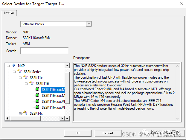
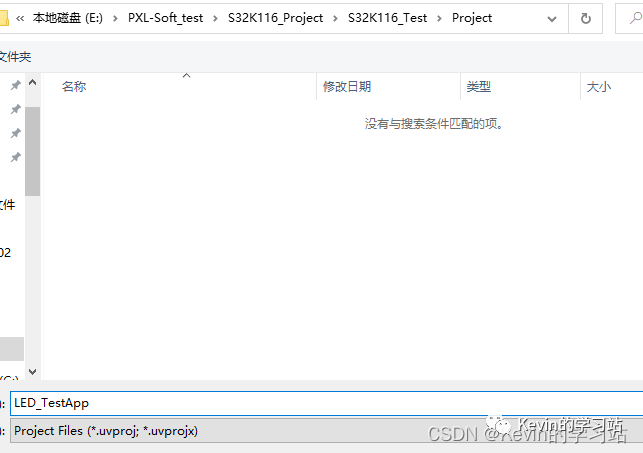 2.2、选择芯片型号,根据需求选择,本次测试采样S32K116
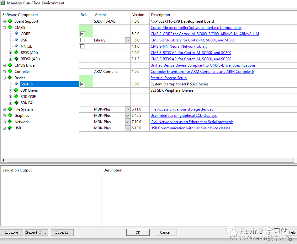
2.3、勾选 CMSIS下的CORE和Device下的Startup,点击OK
2.4、生成如下工程
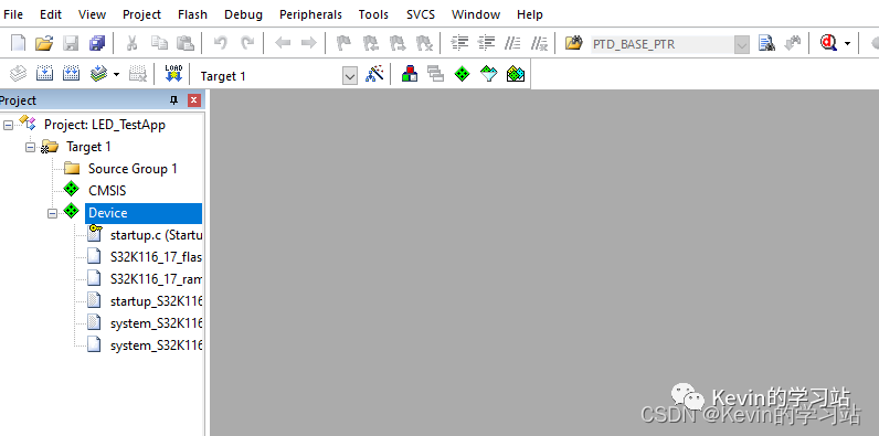
2.5、在工程中添加文件夹
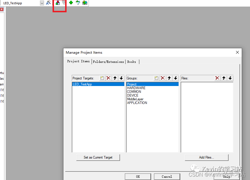
2.6、新建main.c文件,并添加到Project下
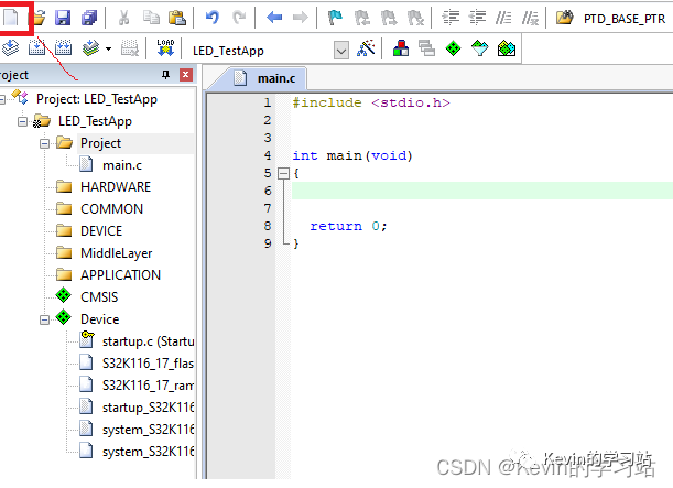
2.7、编译之后会出现报错
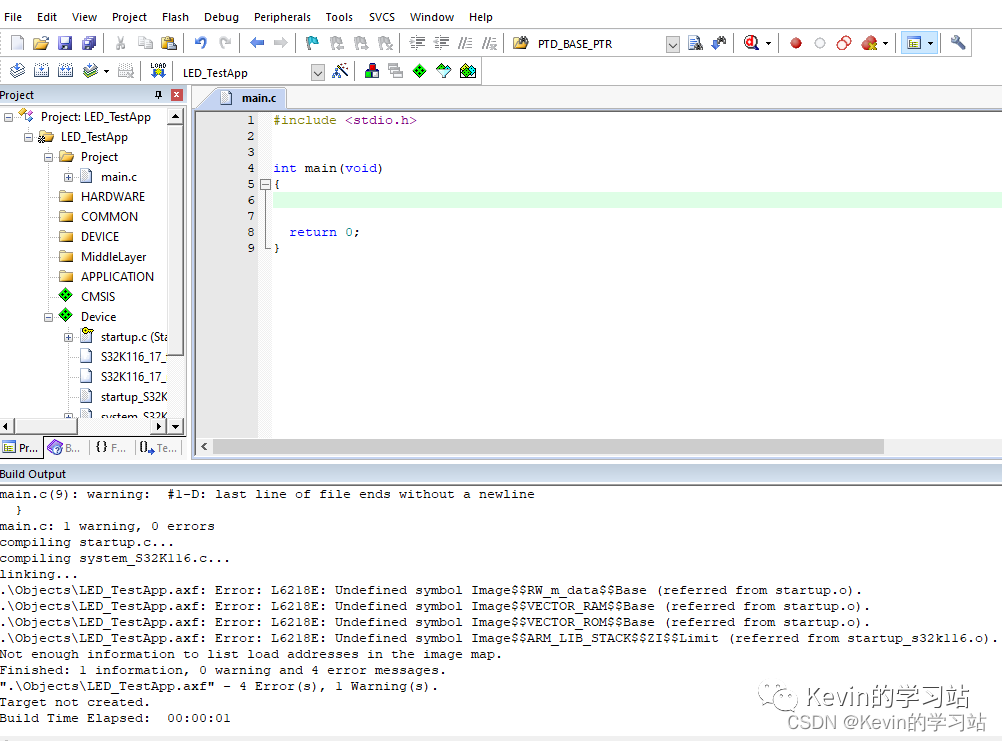 解决如下:
解决如下:
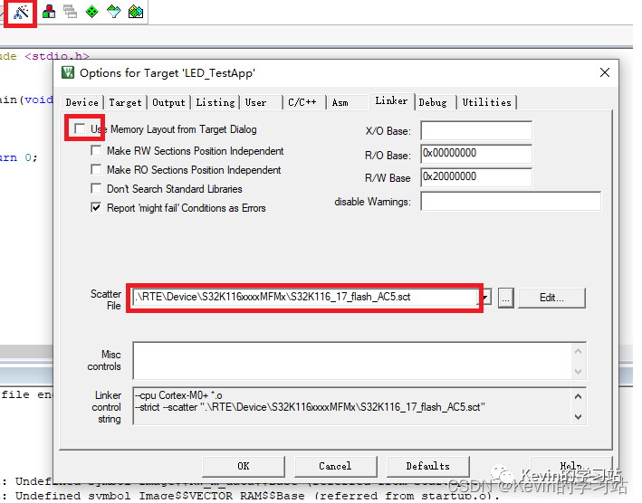
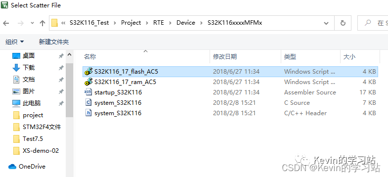
2.8、再次编译,无警告无报错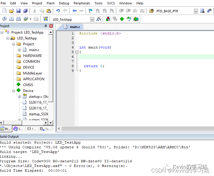
3、验证工程
在HARDWARE文件夹下新建:GPIO.c、GPIO.h两个文件
GPIO.c进行GPIO设置
1#include "GPIO.h"
 2
 3/* 定义五个指针数组保存 GPIOX 的地址 */
 4GPIO_MemMapPtr GPIOX[5] = {PTA, PTB, PTC, PTD, PTE}; //定义五个指针数组保存 GPIOX 的地址
 5PORT_MemMapPtr PORTX[5] = {PORTA, PORTB, PORTC, PORTD, PORTE};
 6
 7
 8void GPIO_PinInit(PTXn_e ptx_n, GPIO_CFG dir, uint8_t data)
 9{
10
11    uint8_t ptx, ptn;
12
13    ptx = PTX(ptx_n);
14    ptn = PTn(ptx_n);
15
16    /* 使能端口时钟 */
17    PCC- >PCCn[PCC_PORTA_INDEX + ptx] = PCC_PCCn_CGC_MASK;
18
19    /* 清除之前的复用功能 */
20    PORTX[ptx]- >PCR[ptn] &= ~(uint32)PORT_PCR_MUX_MASK;
21
22    /* 设置复用功能为GPIO即普通IO口 */
23    PORTX[ptx]- >PCR[ptn] |= PORT_PCR_MUX(1);
24
25    /* 配置GPIO模式 */
26    PORTX[ptx]- >PCR[ptn] |= dir;
27
28    /* 设置GPIO方向 */
29    if (dir)
30    {
31        GPIOX[ptx]- >PDDR |= (uint32)(1 < < ptn);
32    }
33    else
34    {
35        GPIOX[ptx]- >PDDR &= ~(uint32)(1 < < ptn);
36    }
37
38    /* 设置端口默认状态 */
39    if (data)
40    {
41        GPIOX[ptx]- >PDOR |= (uint32)(1 < < ptn);
42    }
43    else
44    {
45        GPIOX[ptx]- >PDOR &= ~(uint32)(1 < < ptn);
46    }
47}
48
49void GPIO_PinWrite(PTXn_e ptx_n, uint8_t data)
50{
51    uint8_t ptx, ptn;
52
53    ptx = PTX(ptx_n);
54    ptn = PTn(ptx_n);
55
56    /* 设置端口默认状态 */
57    if (data)
58    {
59        GPIOX[ptx]- >PDOR |= (uint32)(1 < < ptn);
60    }
61    else
62    {
63        GPIOX[ptx]- >PDOR &= ~(uint32)(1 < < ptn);
64    }
65}
GPIO.h
1#ifndef __GPIO_H_
 2#define __GPIO_H_
 3#include "common.h"
 4#include "stdint.h"
 5#include "S32K116.h"
 6
 7
 8//定义管脚状态
 9typedef enum GPIO_CFG
10{
11    //这里的值不能改!!!
12    GPI         = 0x00,                       //定义管脚输入方向      GPIOx_PDDRn里,0表示输入,1表示输出
13    GPO         = 0x01,                       //定义管脚输出方向
14
15    GPI_DOWN    = 0x02,                       //输入下拉              PORTx_PCRn需要PE=1,PS=0
16    GPI_UP      = 0x03,                       //输入上拉              PORTx_PCRn需要PE=1,PS=1
17    GPI_PF      = 0x10,                       //输入,带无源滤波器,滤波范围:10 MHz ~ 30 MHz 。不支持高速接口( >=2MHz)  0b10000           Passive Filter Enable
18    GPI_DOWN_PF = GPI_DOWN | GPI_PF,          //输入下拉,带无源滤波器
19    GPI_UP_PF   = GPI_UP   | GPI_PF,          //输入上拉,带无源滤波器
20
21    GPO_HDS     = 0x41,                       //输出高驱动能力   0b100 0001    High drive strength
22    GPO_SSR     = 0x05,                       //输出慢变化率     0b101         Slow slew rate
23    GPO_HDS_SSR = GPO_HDS | GPO_SSR,          //输出高驱动能力、慢变化率
24} GPIO_CFG;  //最低位为0,肯定是输入;GPI_UP 和 GPI_UP_PF的最低位为1,其他为输出
25
26
27
28void GPIO_PinInit(PTXn_e ptx_n, GPIO_CFG dir, uint8_t data);
29void GPIO_PinWrite(PTXn_e ptx_n, uint8_t data);
30
31#endif
新建clocks_and_modes_S32K11x.c和clocks_and_modes_S32K11x.h文件,用于初始化系统时钟;
clocks_and_modes_S32K11x.c
1#include "S32K116.h"    /* include peripheral declarations S32K116 */
 2#include "clocks_and_modes_S32K11x.h"
 3
 4void SOSC_init_40MHz(void)
 5{
 6    /*! SOSC Initialization (40 MHz):
 7     * =============================
 8     * */
 9    SCG- >SOSCDIV = SCG_SOSCDIV_SOSCDIV1(1)|
10                   SCG_SOSCDIV_SOSCDIV2(1);     /* SOSCDIV1 & SOSCDIV2 =1: divide by 1      */
11    SCG- >SOSCCFG  = SCG_SOSCCFG_RANGE(3)|       /* Range=3: High frequency range selected   */
12                    SCG_SOSCCFG_EREFS_MASK;     /* HGO=0:   Config xtal osc for low power   */
13                                                  /* EREFS=1: Input is external XTAL          */
14
15  while(SCG- >SOSCCSR & SCG_SOSCCSR_LK_MASK);     /* Ensure SOSCCSR unlocked                          */
16  SCG- >SOSCCSR = SCG_SOSCCSR_SOSCEN_MASK;         /* LK=0:          SOSCCSR can be written                */
17                                                /* SOSCCMRE=0:    OSC CLK monitor IRQ if enabled        */
18                                                /* SOSCCM=0:      OSC CLK monitor disabled          */
19                                                /* SOSCERCLKEN=0: Sys OSC 3V ERCLK output clk disabled */
20                                                /* SOSCLPEN=0:    Sys OSC disabled in VLP modes         */
21                                                /* SOSCSTEN=0:    Sys OSC disabled in Stop modes        */
22                                                /* SOSCEN=1:      Enable oscillator                     */
23
24while(!(SCG- >SOSCCSR & SCG_SOSCCSR_SOSCVLD_MASK));    /* Wait for sys OSC clk valid */
25}
26
27void RUN_mode_48MHz (void)
28{
29    /*! Fast IRC is enabled and trimmed to 48 MHz in reset (default).
30     * Set FIRCDIV1 & FIRCDIV2 = 1: divide by 1 = 48 MHz.
31     * */
32    SCG- >FIRCDIV = SCG_FIRCDIV_FIRCDIV1(1)|
33                   SCG_FIRCDIV_FIRCDIV2(1);
34
35    /*! Fast IRC is enabled in high range (8MHz) in reset (default).
36     * Set FIRCDIV1 & FIRCDIV2 = 1: divide by 1 = 8 MHz.
37     * */
38    SCG- >SIRCDIV = SCG_SIRCDIV_SIRCDIV1(1)|
39                   SCG_SIRCDIV_SIRCDIV2(1);
40
41/*!
42 *  Select FIRC for RUN mode.
43 *  ===========================
44 */
45  SCG- >RCCR=SCG_RCCR_SCS(3)      /* Select FIRC as clock source                                 */
46    |SCG_RCCR_DIVCORE(0b00)      /* DIVCORE=0, div. by 1: Core clock = 48 MHz                     */
47    |SCG_RCCR_DIVBUS(0b00)       /* DIVBUS=0, div. by 1: bus clock = 48 MHz                     */
48    |SCG_RCCR_DIVSLOW(0b01);     /* DIVSLOW=1, div. by 2: SCG slow, flash clock= 24 MHz            */
49
50  while (((SCG- >CSR & SCG_CSR_SCS_MASK) > > SCG_CSR_SCS_SHIFT ) != 3) {}    /* Wait for sys clk src = SPLL */
51}
clocks_and_modes_S32K11x.h
1#ifndef CLOCKS_AND_MODES_S32K11X_H_
2#define CLOCKS_AND_MODES_S32K11X_H_
3
4void SOSC_init_40MHz (void);
5void RUN_mode_48MHz (void);
6
7#endif /* CLOCKS_AND_MODES_S32K11X_H_ */
在main函数中对GPIO进行操作,将GPIO -PTB2设置为输出模式,输出高电平。
main.c
1#include < stdio.h >
 2#include "S32K116.h"    /* include peripheral declarations S32K116 */
 3#include "clocks_and_modes_S32K11x.h"
 4#include "GPIO.h"
 5
 6//关闭看门狗
 7void WDOG_disable (void)
 8{
 9  WDOG- >CNT=0xD928C520;     /* Unlock watchdog         */
10  WDOG- >TOVAL=0x0000FFFF;   /* Maximum timeout value     */
11  WDOG- >CS = 0x00002100;    /* Disable watchdog         */
12}
13
14
15//void LED_init()
16//{
17//        /*LED--*/
18//    PCC- >PCCn[PCC_PORTB_INDEX ]|=PCC_PCCn_CGC_MASK; //使能PTD端口时钟
19//    PORTB- >PCR[2] = PORT_PCR_MUX(1);/* Port : MUX = GPIO                */
20//    PTB- >PDDR |= 1< < 2;               /* Port: Data direction  */
21//    PTB- >PSOR |= 1< < 2;               /* 高电平*/
22////    PTA- >PCOR |= 1< < 2;
23//}
24
25
26int main()
27{
28    WDOG_disable();
29    SOSC_init_40MHz();  /* Initialize system oscillator for 40 MHz xtal */
30    RUN_mode_48MHz();       /* Init clocks: 48 MHz sys, core and bus, 24 MHz flash. */
31//    LED_init();
32
33    GPIO_PinInit(PTB2,GPO,0);
34
35    while(1)
36    {
37        GPIO_PinWrite(PTB2,1);
38    }
39
40    return 0;
41}
添加.h文件路径
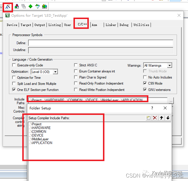
并将S32K116.文件保存在common文件夹下
配置Jlink下载环境
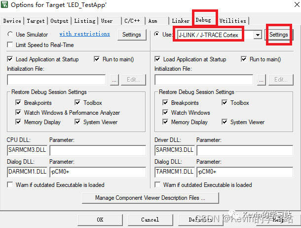 选择S32K116
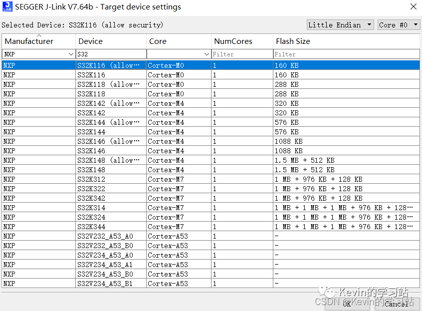
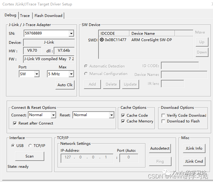
下载工程;用万用表或者示波器即可查看PTB2输出高电平。
声明:本文内容及配图由入驻作者撰写或者入驻合作网站授权转载。文章观点仅代表作者本人,不代表电子发烧友网立场。文章及其配图仅供工程师学习之用,如有内容侵权或者其他违规问题,请联系本站处理。
举报投诉
-
S32K1XX系列MCU复位问题的解决方法2023-08-23 3977
-
S32K1xx开发包和S32K1实时驱动的区别是什么?2023-05-24 648
-
FreeMaster插件模块它支持S32K1xx系列吗?2023-05-06 540
-
S32K3xx EMIOS模块与S32K1xx FTM模块相比有什么优势?2023-03-31 925
-
基于S32K1xx 系列的汽车通用评估板方案2023-03-16 2449
-
如何搭建s32k1xx的环境?2022-02-09 1565
-
keil4怎么新建工程2022-01-27 1278
-
S32K1xx系列MCU的EEE(Emulated EEPROM)使用详解2021-11-18 1887
-
S32K1xx系列MCU启动过程是怎样的2021-11-01 1670
-
vb关闭当前应用重新加载_S32K1xx系列MCU应用指南之芯片锁死(lockup)复位原因分析与恢复方法详解...2021-10-28 1205
-
S32K1xx系列MCU的EEE(Emulated EEPROM)使用详解 精选资料分享2021-09-13 2460
-
NXP半导体产品S32K1XX数据手册下载2021-08-02 1754
-
AN5426,S32K1XX微控制器的硬件设计指南2020-12-22 2045
-
STM32新建工程2020-01-12 3878
全部0条评论

快来发表一下你的评论吧 !

