

某中小型企业网组网案例
描述
1、实验要求
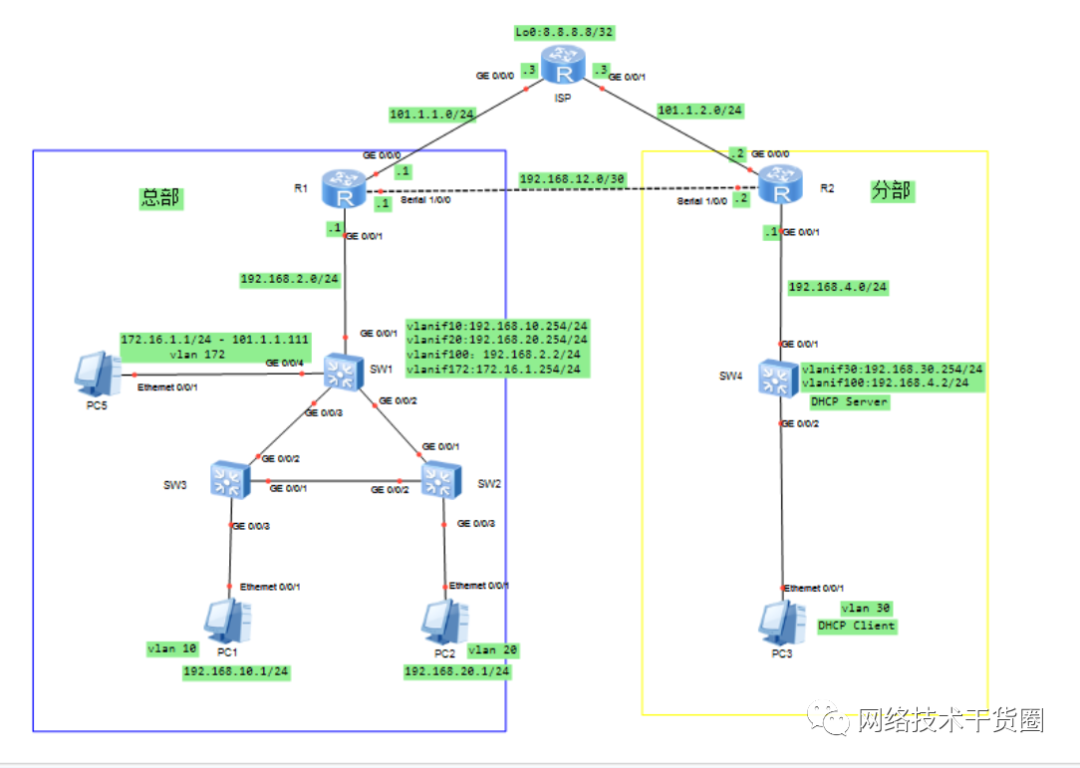
假如你是某公司网管员,要为总部和分部规划网络。左边蓝色区域为总公司内部网络,右边黄色区域为分公司内部网络,上方模拟ISP。
总部交换网络,生成树采用STP,SW1为根桥,优先级0;
R1与SW1之间运行之间运行 OSPF,进程号 1,RID手动设置为环回口地址,起区域验证;
PC5模拟内网服务器,使用公网地址 101.1.1.111 为外网用户提供各种服务;
R2与SW4之间运行OSPF,进程号 1,RID手动设置为环回口地址,起区域验证;
SW4启用DHCP,为vlan30分配ip和网关,名称30,租期2天。
R1/R2配置相应ACL、NAT、默认路由等
总部与分部,实现线路的冗余。这里采用PPP链路实验,实际环境可以采用更好的IPsec VPN。
网络优化,当R2的外网故障时,要求vlan30的主机可以通过PPP链路走R1与外网通信。
等更多,细看代码解读。。。。。。。
2、实验拓扑
3、实验需求
如图所示,配置ISP、R1、R2的公网IP地址和设备名称。
网络的IP规划如下:
R1与ISP相连的网段为101.1.1.0/24;
R2与ISP相连的网段为101.1.2.0/24;
R1与R2相连的网段为192.168.12.0/30;
R1与SW1相连的网段为192.168.2.0/24;
R2与SW4相连的网段为192.168.4.0/24;
PC5的地址为172.16.1.1/24,网关为172.16.1.254/24;(vlan 172)
PC1属于Vlan10,ip地址为:192.168.10.1,网关是192.168.10.254/24;
PC2属于Vlan20,ip地址为:192.168.20.1,网关是192.168.20.254/24;
PC3属于Vlan30,IP地址自动获取,网关是192.168.30.254/24;
R1的loopback0地址为1.1.1.1/32;
R2的loopback0地址为2.2.2.2/32;
SW1的loopback0地址为10.1.1.1/32;
SW4的loopback0地址为10.4.4.4/32;
4、配置思路
4.1 总部配置
4.1.1 在SW1、SW2、SW3上配置交换网络
SW1:
[Huawei] sysname SW1
[SW1] vlan batch 10 20 172
[SW1] interface g0/0/2
[SW1-GigabitEthernet0/0/2] port link-type trunk
[SW1-GigabitEthernet0/0/2] port trunk allow-pass vlan 10 20 172
[SW1-GigabitEthernet0/0/2] interface g0/0/3
[SW1-GigabitEthernet0/0/3] port link-type trunk
[SW1-GigabitEthernet0/0/3] port trunk allow-pass vlan 10 20 172
[SW1-GigabitEthernet0/0/3] interface g0/0/4
[SW1-GigabitEthernet0/0/4] port link-type access
[SW1-GigabitEthernet0/0/3] port default vlan 172
SW2:
[Huawei] sysname SW2
[SW2] vlan batch 10 20 172
[SW2] interface g0/0/2
[SW2-GigabitEthernet0/0/2] port link-type trunk
[SW2-GigabitEthernet0/0/2] port trunk allow-pass vlan 10 20 172
[SW2-GigabitEthernet0/0/2] interface g0/0/1
[SW2-GigabitEthernet0/0/1] port link-type trunk
[SW2-GigabitEthernet0/0/1] port trunk allow-pass vlan 10 20 172
[SW2-GigabitEthernet0/0/1] interface g0/0/3
[SW2-GigabitEthernet0/0/3] port link-type access
[SW2-GigabitEthernet0/0/3] port default vlan 20
SW3:
[Huawei] sysname SW3
[SW3] vlan batch 10 20 172
[SW3] interface g0/0/2
[SW3-GigabitEthernet0/0/2] port link-type trunk
[SW3-GigabitEthernet0/0/2] port trunk allow-pass vlan 10 20 172
[SW3-GigabitEthernet0/0/2] interface g0/0/1
[SW3-GigabitEthernet0/0/1] port link-type trunk
[SW3-GigabitEthernet0/0/1] port trunk allow-pass vlan 10 20 172
[SW3-GigabitEthernet0/0/1] interface g0/0/3
[SW3-GigabitEthernet0/0/3] port link-type access
[SW3-GigabitEthernet0/0/3] port default vlan 10
4.1.2 SW1、SW2、SW3 运行 STP,且 SW1 为根桥
# SW1:
[SW1] stp mode stp
[SW1] stp priority 0

# SW2:
[SW2] stp mode stp

# SW3:
[SW3] stp mode stp
4.1.3 查看 SW1 的 stp 状态,确保是根桥
4.1.4 SW1 上创建 VLAN 网关
[SW1] interface vlanif 10
[SW1-Vlanif10] ip address 192.168.10.254 24
[SW1-Vlanif10] interface vlanif 20
[SW1-Vlanif20] ip address 192.168.20.254 24
[SW1-Vlanif20] interface vlanif 172
[SW1-Vlanif172] ip address 172.16.1.254 24
4.1.5 SW1、R1 进行配置,使得可以通信
SW1:
[SW1] interface loopback 0
[SW1-LoopBack0] ip address 10.1.1.1 32
[SW1] vlan 100
[SW1-vlan100] interface vlanif 100
[SW1-Vlanif100] ip address 192.168.2.2 24
[SW1] interface g0/0/1
[SW1-GigabitEthernet0/0/1] port link-type access
[SW1-GigabitEthernet0/0/1] port default vlan 100
R1:
[Huawei] sysname R1
[R1] interface g0/0/1
[R1-GigabitEthernet0/0/1] ip address 192.168.2.1 24
[R1-GigabitEthernet0/0/1] interface loopback 0
[R1-LoopBack0] ip address 1.1.1.1 32
4.1.6 SW1、R1 配置 OSPF,并配置区域验证,密文显示。
SW1:
[SW1] ospf 1 router-id 10.1.1.1
[SW1-ospf-1] area 1
[SW1-ospf-1-area-0.0.0.1] network 10.1.1.1 0.0.0.0
[SW1-ospf-1-area-0.0.0.1] network 192.168.2.0 0.0.0.255
[SW1-ospf-1-area-0.0.0.1] network 192.168.10.0 0.0.0.255
[SW1-ospf-1-area-0.0.0.1] network 192.168.20.0 0.0.0.255
[SW1-ospf-1-area-0.0.0.1] network 172.16.1.0 0.0.0.255
[SW1-ospf-1-area-0.0.0.1] authentication-mode md5 1 cipher huawei
R1:
[R1] ospf 1 router-id 1.1.1.1
[R1-ospf-1] area 1
[R1-ospf-1-area-0.0.0.1] network 192.168.2.0 0.0.0.255
[R1-ospf-1-area-0.0.0.1] authentication-mode md5 1 cipher huawei
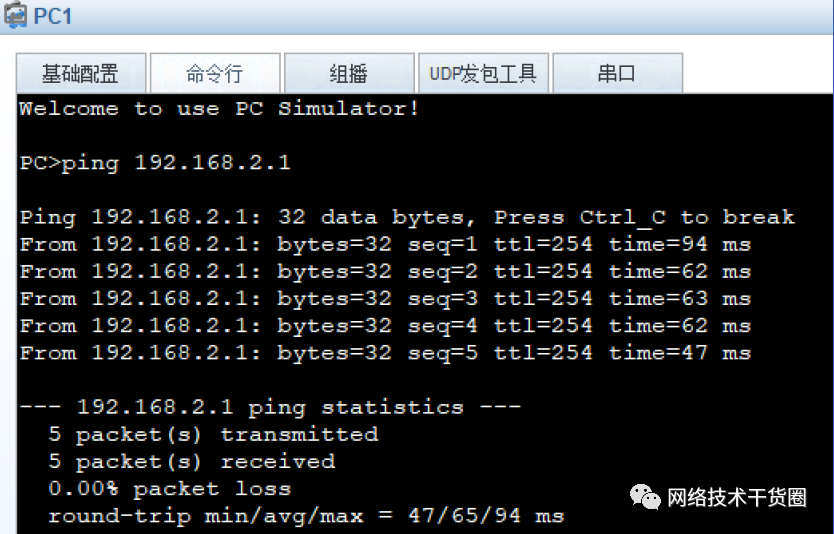
4.1.7 检查 R1 上可以学习到 VLAN10、20、172 的路由,主机能与 R1 互通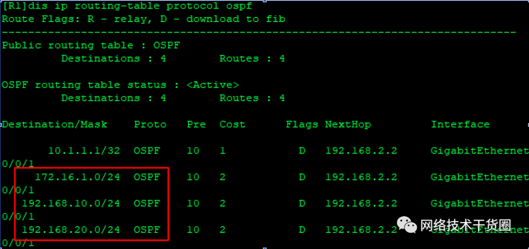
4.1.8 配置ISP相应接口
[ISP] interface g0/0/0
[ISP-GigabitEthernet0/0/0] ip add 101.1.1.3 24
[ISP-GigabitEthernet0/0/0] interface g0/0/01
[ISP-GigabitEthernet0/0/1] ip address 101.1.2.3 24
[ISP-GigabitEthernet0/0/1] interface loopback 0
[ISP-LoopBack0] ip address 8.8.8.8 32
4.1.9 R1、SW1 配置相应接口、默认路由、NAT
PC5模拟内网服务器,使用公网地址 101.1.1.111 为外网用户提供各种服务
SW1:
[SW1] ip route-static 0.0.0.0 0.0.0.0 192.168.2.1
R1:
[R1] ip route-static 0.0.0.0 0.0.0.0 101.1.1.3
[R1] acl 2000
[R1-acl-basic-2000] rule 5 permit source 192.168.10.0 0.0.0.255
[R1-acl-basic-2000] rule 10 permit source 192.168.20.0 0.0.0.255
[R1] interface g0/0/0
[R1-GigabitEthernet0/0/0] ip add 101.1.1.1 24
[R1-GigabitEthernet0/0/0] nat outbound 2000
[R1-GigabitEthernet0/0/0] nat static global 101.1.1.111 inside 172.16.1.1 netmask 255.255.255.255

*说明:此处使用nat server global 101.1.1.111 inside 172.16.1.1也可以,没有区别。
4.1.10 检查 PC 机与 ISP 通信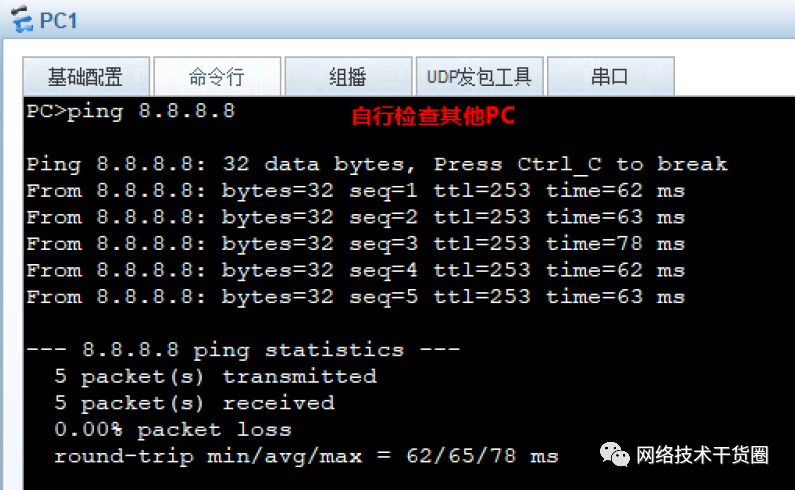
4.2 分部配置
4.2.1 在 SW 4上配置交换网络
SW4:
[Huawei] sysname SW4
[SW4] vlan 30
[SW4-vlan30] interface g0/0/2
[SW4-GigabitEthernet0/0/2] port link-type access
[SW4-GigabitEthernet0/0/2] port default vlan 30
4.2.2 在 SW4 上配置 DHCP
SW4:
[SW4] interface vlanif 30
[SW4-Vlanif30] ip address 192.168.30.254 24
[SW4] ip pool 30
[SW4-ip-pool-30] gateway-list 192.168.30.254
[SW4-ip-pool-30] network 192.168.30.0 mask 255.255.255.0
[SW4-ip-pool-30] lease day 2
[SW4] interface vlanif 30
[SW4-Vlanif30] dhcp select global
4.2.3 检查 PC3 可以正常获取地址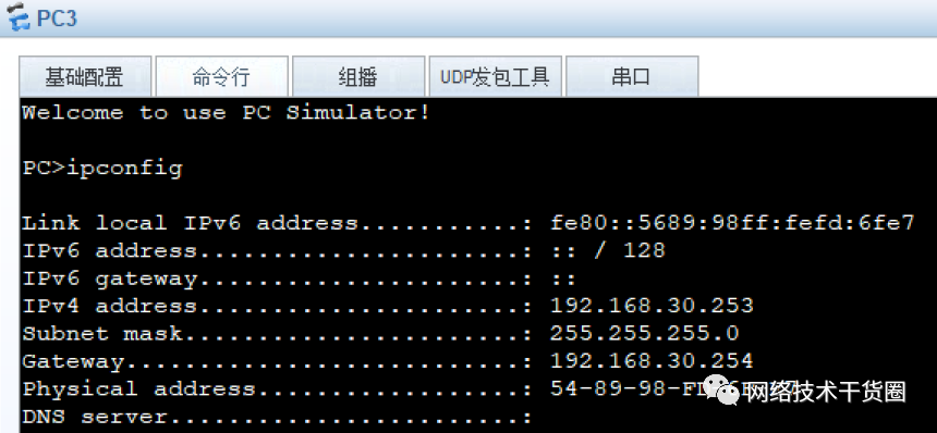
4.2.4 SW4、R2 进行配置,使得可以通信
SW4:
[SW4] vlan 100
[SW4-vlan100] interface vlanif 100
[SW4-Vlanif100] ip address 192.168.4.2 24
[SW4-Vlanif100] interface g0/0/1
[SW4-GigabitEthernet0/0/1] port link-type access
[SW4-GigabitEthernet0/0/1] port default vlan 100
[SW4-GigabitEthernet0/0/1] interface lo 0
[SW4-LoopBack0] ip address 10.4.4.4 32
R2:
[Huawei] sysname R2
[R2] interface g0/0/1
[R2-GigabitEthernet0/0/1] ip address 192.168.4.1 24
[R2-GigabitEthernet0/0/1] interface loopback 0
[R2-LoopBack0] ip address 2.2.2.2 32
4.2.5 SW4、R4 配置 OSPF,并起区域验证。
SW4:
[SW4] ospf 1 router-id 10.4.4.4
[SW4-ospf-1] area 2
[SW4-ospf-1-area-0.0.0.2] network 192.168.30.0 0.0.0.255
[SW4-ospf-1-area-0.0.0.2] network 10.4.4.4 0.0.0.0
[SW4-ospf-1-area-0.0.0.2] network 192.168.4.0 0.0.0.255
[SW4-ospf-1-area-0.0.0.2] authentication-mode md5 1 cipher huawei
R2:
[R2] ospf 1 router-id 2.2.2.2
[R2-ospf-1] area 2
[R2-ospf-1-area-0.0.0.2] network 2.2.2.2 0.0.0.0
[R2-ospf-1-area-0.0.0.2] network 192.168.4.0 0.0.0.255
[R2-ospf-1-area-0.0.0.2] authentication-mode md5 1 cipher huawei
4.2.6 检查 R2 上可以学习到 VLAN30 的路由,主机能与 R2 互通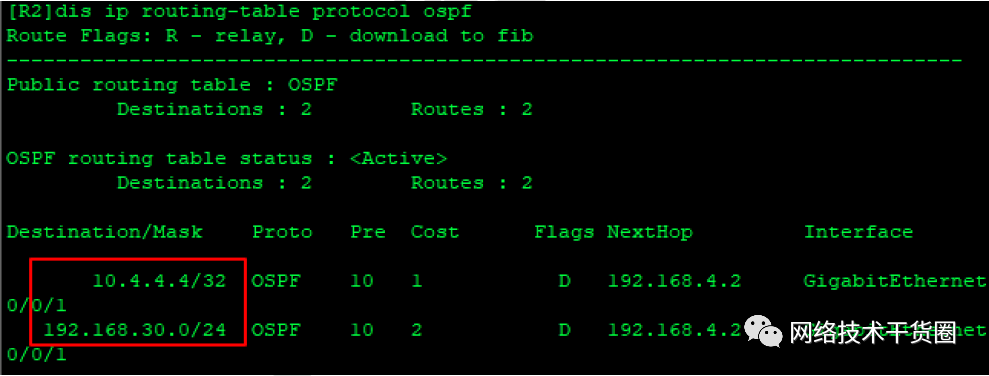
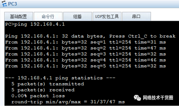
4.2.7 R2、SW4 配置相应接口、默认路由、NAT
SW4:
[SW4] ip route-static 0.0.0.0 0.0.0.0 192.168.4.1

R2:
[R2] ip route-static 0.0.0.0 0.0.0.0 101.1.2.3
[R2] acl 2000
[R2-acl-basic-2000] rule 5 permit source 192.168.30.0 0.0.0.255
[R2] interface g0/0/0
[R2-GigabitEthernet0/0/0] ip address 101.1.2.2 24
[R2-GigabitEthernet0/0/0] nat outbound 2000
4.2.8 检查 PC 机与 ISP 通信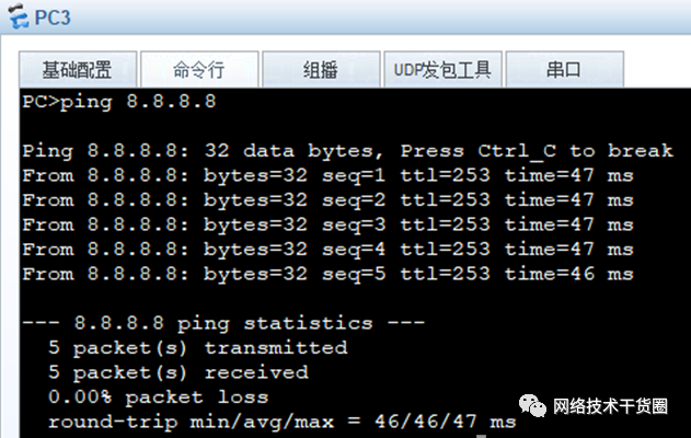
4.3 配置总部和分部互联
4.3.1 配置 R1 的 AAA
R1为认证方,R2为被认证方,使用CHAP验证。
用户名为:zongbu,密码为:huawei,服务器类型为PPP。
R1:
[R1-aaa] local-user zongbu password cipher huawei
[R1-aaa] local-user zongbu service-type ppp
4.3.2 配置 R1 的 IP,并为 R2 分配地址,采用 CHAP 认证
# R1:
[R1] interface s1/0/0
[R1-Serial1/0/0] ip address 192.168.12.1 30
[R1-Serial1/0/0] remote address 192.168.12.2
[R1-Serial1/0/0] ppp authentication-mode chap

# R2:
[R2] interface s1/0/0
[R2-Serial1/0/0] ppp chap user zongbu
[R2-Serial1/0/0] ppp chap password cipher huawei
[R2-Serial1/0/0] ip address ppp-negotiate
4.3.3 R1、R2 配置 ospf,启用区域MD5验证,key-id为1,密码为huawei
R1:
[R1] ospf 1
[R1-ospf-1] area 0
[R1-ospf-1-area-0.0.0.0] network 1.1.1.1 0.0.0.0
[R1-ospf-1-area-0.0.0.0] network 192.168.12.0 0.0.0.3
[R1-ospf-1-area-0.0.0.0] authentication-mode md5 1 cipher huawei
R2:
[R2] ospf 1
[R1-ospf-1] area 0
[R1-ospf-1-area-0.0.0.0] network 2.2.2.2 0.0.0.0
[R1-ospf-1-area-0.0.0.0] network 192.168.12.0 0.0.0.3
[R1-ospf-1-area-0.0.0.0] authentication-mode md5 1 cipher huawei
4.3.4 验证 PC1、PC2 能与 PC3 通信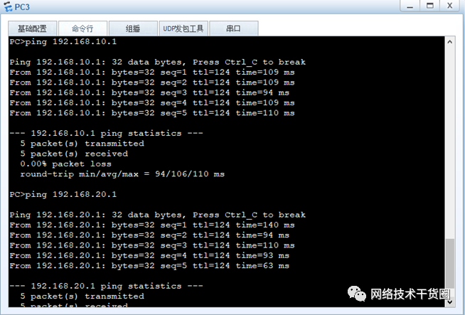
4.4 网络优化
4.4.1 在 R1 和 R2 上配置,实现线路的冗余
当R2的外网故障时,要求vlan30的主机可以通过PPP链路走R1与外网通信。
# R1
[R1] acl 2000
[R1-acl-basic-2000] rule permit source 192.168.30.0 0.0.0.255

# R2
[R2] ip route-static 0.0.0.0 0.0.0.0 192.168.12.1 preference 70
完结,配置完成。。
审核编辑:汤梓红
-
新代智能制造云端服务 解决中小型企业痛点2018-01-16 2013
-
区块链为中小型企业提供了怎样的战略机遇2018-08-06 1209
-
物联网将对中小型企业有何影响?2018-10-08 4626
-
为什么未来十年是中小型企业发展SaaS的好时机2019-12-27 885
-
中小型企业应该如何应对网络安全2020-05-15 1389
-
西部数据通过闪存创新助力中小型企业和居家办公人员使用NAS2021-10-09 2299
-
适合中小型企业的智能网关都有哪些2022-06-30 2291
-
什么样的ERP软件企业适合中小型生产制造企业2023-03-31 1226
-
华为云网站安全解决方案:中小型企业的云上云下安全守护专家2023-04-19 1090
-
中小型企业向数字化转型可以带来哪些益处?_光点科技2023-06-07 1390
-
如何选择适合中小型企业的BGA返修设备?2023-07-06 862
-
中小型企业SDWAN组网时应考虑的10大方面2023-08-03 1058
-
希捷Self-Encrypting驱动器和LSI SafeStore简化加密和中小型企业的数据安全2023-08-11 684
-
中小型企业SD-WAN组网:关键考虑因素与最佳实践2023-09-05 1601
-
中小型企业网络组网首选什么方案好?2024-10-24 2246
全部0条评论

快来发表一下你的评论吧 !

