
如何用XSCT通过APB接口来读GT的寄存器
描述
在debug GT的时候,有时候需要读出一些寄存器来分析。这篇文章介绍一种通过AXI4 Lite或者APB3接口从XSCT来读Versla GT的寄存器的方法。
APB3是一个32-bit数据总线地址,但是AXI4-Lite是一个8-bit Byte总线。因此如果用AXI-lite,需要将如下的寄存器地址*4。
Example的步骤如下:
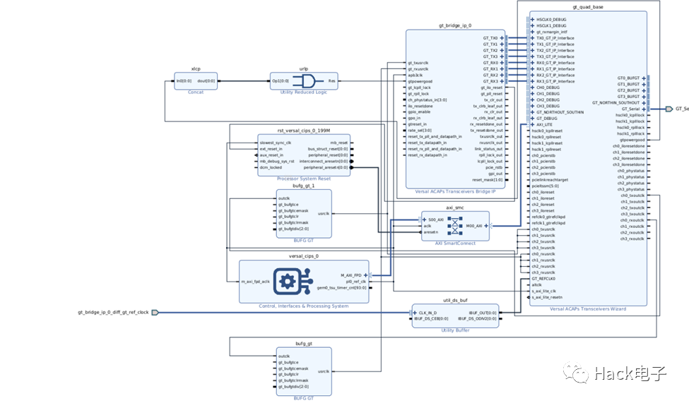
Create block design + Add bridge IP。
选择10G base-KR作为模板,选择AXI4 Lite选项生成GTY example。
IPI里Block design将CIPS的FPD和AXI Lite接口相连。
增加一个AXI smart connect从CIPS到APB接口。
Create wrapper,Block design如下框图。
Note:如果是APB3,是4 Bytes地址,更适合通过VIO或者是Fabric 接口来访问。

从Address editor可以看到地址是0xA4000000,比如对地址为0xC3C来说,对应AXI地址为0xA40000000 + (0xC3C *4) = 0xA40030F0.

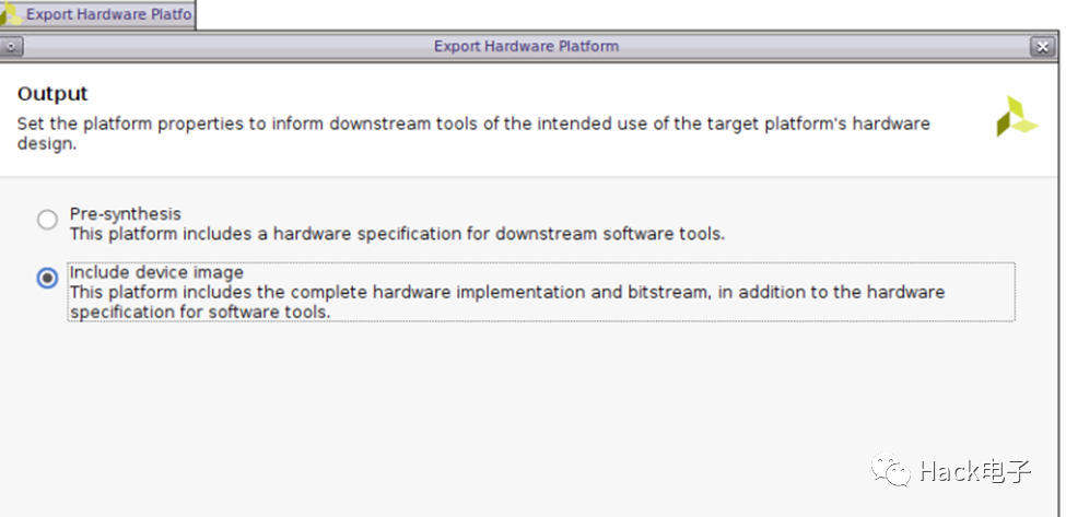
Crate wrapper,实现完成,就可以export hardware

Tools Launch Vitis IDE, 用export的hardware,创建一个hello world的application。最后download到vck190之后,就可用tcl完成读寄存器。下面提供两个example来做一个demo:
Example 1:读0xA40030F0之后的比如32个寄存器
proc read_reg {number} {
set outfile [open "output1.txt" w+]
set start 0xA40030F0
puts $outfile [mrd -force $start $number]
close $outfile
}
Copy到xsct,执行完read_reg 32,就会在工程目录下看到32个寄存器导出到output1.txt,起始地址和寄存器数可以修改.
同样下面的example 2,是用来monitor KH,KL和GC。
Example 2: monitor KH, KL, and GC for Channel 0
proc monitor {} {
set outfile [open "output2.txt" w+]
#read 0x0CBA *4 = 0x32E8; 0x0C3C * 4 = 4 0x30F0
#set 0x0CBA[7] = 1'b1
#0x0CBA[6:4] = 3'b000
# 0x0CBA[3:1] = 3'b000
#0x0CBA[0] = 1'b1
# 0x0C3C[28:27] = 2'b00
puts $outfile "########### read 0x0CBA and 0x0C3C ###########"
puts $outfile [mrd 0xA40032E8]
puts $outfile [mrd 0xA40030F0]
puts $outfile "########### write 0x0CBA and 0x0C3C ###########"
mwr -size b 0xA40032E8 {0x81} 1
mwr 0xA40030F0 [expr [mrd -value 0xA40030F0] & 0xE7FFFFFF]
puts $outfile "########### read 0x0CBA and 0x0C3C ###########"
puts $outfile [mrd 0xA40032E8]
puts $outfile [mrd 0xA40030F0]
#read 0x08A4[7:0] *4 = 0x2290
#read 0x08A5[23:16] *4 = 0x2294
#read 0x08A6[23:16] *4 = 0x2298
puts $outfile "########### read KH, KL, GC ###########"
puts $outfile [mrd -size b 0xA4002290 1]
puts $outfile [mrd -size b 0xA4002296 1]
puts $outfile [mrd -size b 0xA400229A 1]
close $outfile
}
审核编辑:汤梓红
-
TVP5150是不是可以通过读什么寄存器来判断是否有视频输入?2025-02-10 303
-
接口的控制与状态寄存器什么作用2024-10-17 2109
-
CPSR寄存器和APSR寄存器的组成2023-10-20 6467
-
寄存器是什么?怎么操作寄存器点亮LED灯?2023-07-21 5067
-
ARM通用寄存器及状态寄存器详解2023-01-06 9461
-
UART寄存器介绍与中断操作详解2020-08-25 17418
-
寄存器变量2019-06-03 2837
-
如何使用寄存器级读&写控制基于PXI平台的FPGA2017-10-19 857
-
如何使用寄存器级读&写控制基于PXI平台的FPGA2017-10-16 953
-
寄存器与移位寄存器2016-05-20 1245
-
寄存器,寄存器是什么意思2010-03-08 22205
-
读寄存器内容的源代码2010-02-09 475
-
带像素读掩摸寄存器的像素处理单元的工作和结构2009-06-11 510
-
寄存器寻址方式2009-03-14 3033
全部0条评论

快来发表一下你的评论吧 !

