
如何使用ESP32摄像头模块构建简单的CCTV安全摄像头
描述
我们将向您展示如何使用 ESP32 摄像头模块构建自己的简单 CCTV安全摄像头。从修改硬件连接到编码功能和启用远程访问,加入我们的分步教程,打造经济高效且可定制的监控解决方案。
我们需要构建这些部件的组件是:
ESP32 凸轮
FTDI编程器
跳线
亚克力切割身体部位
Micro-SD卡
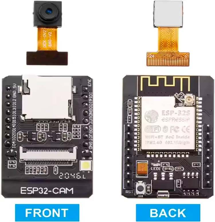
ESP32 摄像头模组
ESP32 相机是由乐鑫科技开发的一款功能强大、用途广泛的微控制器,以其双核处理能力、内置 Wi-Fi 和蓝牙功能以及丰富的 GPIO
引脚阵列而闻名,使其成为各种物联网应用的首选。其双核架构允许同时执行任务,从而能够高效处理复杂的操作。
之前,我们已经使用 ESP32 摄像头模组构建了智能考勤系统和口罩检测系统,如果您有兴趣,可以查看这两个项目。

ESP32 摄像头模组引脚排列
ESP32 CAM 模组通常具有引脚排列,其中包括各种 GPIO 引脚,可实现多功能连接。

通常,它包括电源和接地引脚、用于相机的 GPIO 引脚、用于存储扩展的 SD 卡插槽、用于串行通信的 UART 引脚以及可用于各种用途的通用 GPIO
引脚,例如 I2C 或 SPI
通信、数字输入/输出,或用于与传感器和执行器连接。此外,它还通常包括用于启用闪存、控制相机以及促进启动和复位等编程模式的引脚。
FTDI 模块引脚排列
FTDI模块也称为(Future Technology Devices International)模块。

它通常用于 USB 到串行通信,通常具有包括以下引脚排列:
RXD(接收数据):这是FTDI芯片从外部设备接收数据的地方。
TXD(传输数据):从FTDI芯片传输到外部设备的数据通过此引脚发送出去。
CTS(清除发送):也与硬件流控制有关,此引脚向 FTDI 芯片指示外部设备已准备好接收数据。
DTR(数据终端就绪):此引脚通常用于复位或控制外部设备。
5V 或 3.3V:根据模块的不同,它提供 5 伏或 3.3 伏的电源输出。
GND(接地):接地引脚为模块提供参考电压。
搭建 ESP32 DIY 监控摄像头的分步教程
现在,在您获得相关信息后,让我们逐步了解该项目的制作过程: -
a) 设置开发环境:
安装 Arduino IDE。
将 ESP32 开发板添加到 Arduino
IDE。复制以下链接“https://espressif.github.io/arduino-esp32/package_esp32_index.json”,并将其粘贴到“文件》首选项”》其他板管理器中的新行中。

从 tools》boards》manage 库中安装 ESP32 摄像头模组所需的库,并在搜索栏中输入“esp32”,然后通过 expressif
安装库。

b) 接线:
FTDI 模组与 ESP32 CAM 的接线非常简单。

将 ESP32 CAM 的 Vcc 连接到 FTDI 的 5V 引脚。将 ESP32 CAM 的 GND 连接到 FTDI 的 GND。将 ESP32
CAM 的 RX 引脚连接到 FTDI 的 TX 引脚。将 ESP32 CAM 的 TX 引脚连接到 FTDI 的 RX 引脚。将 GPIO0 连接到
GND,以便您可以在 ESP32 中上传代码。
c) 如何使用 Arduino IDE 对 ESP32 CAM 进行编程?
安装 ESP32 开发板后,进入工具》开发板》ESP32 Arduino 和 Select Ai thinker ESP32 Cam 开发板。

完成后,转到文件》示例》ESP32》相机 Web 服务器并打开代码
您需要在命令前面添加 // 并将其从 #define CAMERA_MODEL_AI_THINKER 中删除 #define
CAMERA_MODEL_ESP_EYE。

接下来,将“hotspot”和“hotspotpassword”字符串替换为手机的热点ssid和密码,然后上传代码。

d) 在浏览器上测试
获取串行监视器的 IP 地址,然后将其写入您的移动浏览器。
完成后,按开始流选项,您将看到相机馈送。
e) 外壳设计和组装
我想让设计尽可能简单易行。因此,我用了一张简单的图表纸作为相机的主体。如果你想要一个更耐用的身体。.您也可以使用PVC管或3D打印外壳。

对于前板和后板,我使用了onshape并对其进行了设计,然后进行了激光切割。

然后,我们将 esp32 凸轮组装到外壳中,这就是最终项目的样子。

//Code for ESP32 CCTV Security Camera


#include "esp_camera.h"

#include < WiFi.h >


// WARNING!!! PSRAM IC required for UXGA resolution and high JPEG quality

//            Ensure ESP32 Wrover Module or other board with PSRAM is selected

//            Partial images will be transmitted if image exceeds buffer size

//

//            You must select partition scheme from the board menu that has at least 3MB APP space.

//            Face Recognition is DISABLED for ESP32 and ESP32-S2, because it takes up from 15

//            seconds to process single frame. Face Detection is ENABLED if PSRAM is enabled as well


// ===================

// Select camera model

// ===================

//#define CAMERA_MODEL_WROVER_KIT // Has PSRAM

//#define CAMERA_MODEL_ESP_EYE // Has PSRAM

//#define CAMERA_MODEL_ESP32S3_EYE // Has PSRAM

//#define CAMERA_MODEL_M5STACK_PSRAM // Has PSRAM

//#define CAMERA_MODEL_M5STACK_V2_PSRAM // M5Camera version B Has PSRAM

//#define CAMERA_MODEL_M5STACK_WIDE // Has PSRAM

//#define CAMERA_MODEL_M5STACK_ESP32CAM // No PSRAM

//#define CAMERA_MODEL_M5STACK_UNITCAM // No PSRAM

#define CAMERA_MODEL_AI_THINKER // Has PSRAM

//#define CAMERA_MODEL_TTGO_T_JOURNAL // No PSRAM

//#define CAMERA_MODEL_XIAO_ESP32S3 // Has PSRAM

// ** Espressif Internal Boards **

//#define CAMERA_MODEL_ESP32_CAM_BOARD

//#define CAMERA_MODEL_ESP32S2_CAM_BOARD

//#define CAMERA_MODEL_ESP32S3_CAM_LCD

//#define CAMERA_MODEL_DFRobot_FireBeetle2_ESP32S3 // Has PSRAM

//#define CAMERA_MODEL_DFRobot_Romeo_ESP32S3 // Has PSRAM

#include "camera_pins.h"


// ===========================

// Enter your WiFi credentials

// ===========================

const char* ssid = "ssid";

const char* password = "password";


void startCameraServer();

void setupLedFlash(int pin);


void setup() {

  Serial.begin(115200);

  Serial.setDebugOutput(true);

  Serial.println();


  camera_config_t config;

  config.ledc_channel = LEDC_CHANNEL_0;

  config.ledc_timer = LEDC_TIMER_0;

  config.pin_d0 = Y2_GPIO_NUM;

  config.pin_d1 = Y3_GPIO_NUM;

  config.pin_d2 = Y4_GPIO_NUM;

  config.pin_d3 = Y5_GPIO_NUM;

  config.pin_d4 = Y6_GPIO_NUM;

  config.pin_d5 = Y7_GPIO_NUM;

  config.pin_d6 = Y8_GPIO_NUM;

  config.pin_d7 = Y9_GPIO_NUM;

  config.pin_xclk = XCLK_GPIO_NUM;

  config.pin_pclk = PCLK_GPIO_NUM;

  config.pin_vsync = VSYNC_GPIO_NUM;

  config.pin_href = HREF_GPIO_NUM;

  config.pin_sccb_sda = SIOD_GPIO_NUM;

  config.pin_sccb_scl = SIOC_GPIO_NUM;

  config.pin_pwdn = PWDN_GPIO_NUM;

  config.pin_reset = RESET_GPIO_NUM;

  config.xclk_freq_hz = 20000000;

  config.frame_size = FRAMESIZE_UXGA;

  config.pixel_format = PIXFORMAT_JPEG; // for streaming

  //config.pixel_format = PIXFORMAT_RGB565; // for face detection/recognition

  config.grab_mode = CAMERA_GRAB_WHEN_EMPTY;

  config.fb_location = CAMERA_FB_IN_PSRAM;

  config.jpeg_quality = 12;

  config.fb_count = 1;


  // if PSRAM IC present, init with UXGA resolution and higher JPEG quality

  //                      for larger pre-allocated frame buffer.

  if(config.pixel_format == PIXFORMAT_JPEG){

    if(psramFound()){

      config.jpeg_quality = 10;

      config.fb_count = 2;

      config.grab_mode = CAMERA_GRAB_LATEST;

    } else {

      // Limit the frame size when PSRAM is not available

      config.frame_size = FRAMESIZE_SVGA;

      config.fb_location = CAMERA_FB_IN_DRAM;

    }

  } else {

    // Best option for face detection/recognition

    config.frame_size = FRAMESIZE_240X240;

#if CONFIG_IDF_TARGET_ESP32S3

    config.fb_count = 2;

#endif

  }


#if defined(CAMERA_MODEL_ESP_EYE)

  pinMode(13, INPUT_PULLUP);

  pinMode(14, INPUT_PULLUP);

#endif


  // camera init

  esp_err_t err = esp_camera_init(&config);

  if (err != ESP_OK) {

    Serial.printf("Camera init failed with error 0x%x", err);

    return;

  }


  sensor_t * s = esp_camera_sensor_get();

  // initial sensors are flipped vertically and colors are a bit saturated

  if (s- >id.PID == OV3660_PID) {

    s- >set_vflip(s, 1); // flip it back

    s- >set_brightness(s, 1); // up the brightness just a bit

    s- >set_saturation(s, -2); // lower the saturation

  }

  // drop down frame size for higher initial frame rate

  if(config.pixel_format == PIXFORMAT_JPEG){

    s- >set_framesize(s, FRAMESIZE_QVGA);

  }


#if defined(CAMERA_MODEL_M5STACK_WIDE) || defined(CAMERA_MODEL_M5STACK_ESP32CAM)

  s- >set_vflip(s, 1);

  s- >set_hmirror(s, 1);

#endif


#if defined(CAMERA_MODEL_ESP32S3_EYE)

  s- >set_vflip(s, 1);

#endif


// Setup LED FLash if LED pin is defined in camera_pins.h

#if defined(LED_GPIO_NUM)

  setupLedFlash(LED_GPIO_NUM);

#endif


  WiFi.begin(ssid, password);

  WiFi.setSleep(false);


  while (WiFi.status() != WL_CONNECTED) {

    delay(500);

    Serial.print(".");

  }

  Serial.println("");

  Serial.println("WiFi connected");


  startCameraServer();


  Serial.print("Camera Ready! Use 'http://");

  Serial.print(WiFi.localIP());

  Serial.println("' to connect");

}


void loop() {

  // Do nothing. Everything is done in another task by the web server

  delay(10000);

}
审核编辑:陈陈
-
esp32是如何与摄像头连接的呢?2024-06-28 1119
-
ESP32如何传输摄像头视频码流?2023-10-17 651
-
使用ESP32-S3搭建网络摄像头2023-09-06 9215
-
ESP32触屏摄像头2023-06-27 866
-
esp32的模组中没有摄像头的硬件接口,请问它是如何与摄像头连接的呢?2023-03-13 901
-
什么是ESP32-CAM摄像头?2023-02-17 30599
-
基于ESP32的安全摄像头设计2022-12-27 735
-
ESP32 CAM:遥控物体检测摄像头2022-12-15 1360
-
带有ESP32的Discord安全摄像头2022-11-08 864
-
如何对ESP32 AUDIO OV2640摄像头的音频进行调试呢2022-02-15 1253
-
ESP32 AUDIO OV2640摄像头 音频调试日记2021-12-16 1530
-
回收手机摄像头 收购手机摄像头2021-07-05 2869
-
回收苹果摄像头 收购苹果摄像头2020-12-29 1814
-
u***摄像头如何改成水下无线摄像头2018-01-31 19260
全部0条评论

快来发表一下你的评论吧 !

