

企业网络搭建三层架构与实验详解
通信网络
描述
前言
一、channel(cisco)/Eth-Trunk(华为)
网关作为了一个广播域的中心出口;生成树的根网桥也是一棵树的中心,也是流量的集合点;
若将两者分配不同的设备将导致网络通讯资源浪费,故强烈建议两者在同一台设备上;
若使用基于vlan或基于分组的STP协议来工作三层架构中,将导致vlan间或组间通讯时对汇聚层间链路带宽要求较高,可以通过 以太网通道 channel (cisco ) 以太网中继Eth-Trunk(华为) 技术来解决
通道技术将多个接口逻辑的整合为一个接口,实现带宽叠加的作用;
配置要求:
1、通道的对端必须为同一台设备;
2、通道的所有物理接口应该具有相同的速率、双工模式;相同的类型,相同的vlan允许列表;
[sw1]interface Eth-Trunk 0  创建通道接口
[sw1-Eth-Trunk0]q
[sw1]interface GigabitEthernet 0/0/1  将物理接口加入到通道内
[sw1-GigabitEthernet0/0/1]eth-trunk 0
[sw1-GigabitEthernet0/0/1]int g0/0/2
[sw1-GigabitEthernet0/0/2]eth-trunk 0

[sw1-Eth-Trunk0]load-balance ?    基于流的选择
  dst-ip       According to destination IP hash arithmetic
  dst-mac      According to destination MAC hash arithmetic
  src-dst-ip   According to source/destination IP hash arithmetic
  src-dst-mac  According to source/destination MAC hash arithmetic
  src-ip       According to source IP hash arithmetic
  src-mac      According to source MAC hash arithmetic

[sw1-Eth-Trunk0]load-balance { ip | packet-all }   修改基于流或者基于包
注:华为设备,之后设备的配置进入eth-trunk口修改;
三层通道:成为通道的所有物理链路必须先为三层接口;其意义在于将多个需要配置ip地址的接口逻辑为一个接口,配置一个ip地址即可
[sw1]interface Eth-Trunk 0
[sw1-Eth-Trunk0]undo portswitch   切换为3层接口
[sw1-Eth-Trunk0]ip add 192.168.1.1 255.255.255.0  配置ip地址

[sw1]interface GigabitEthernet 0/0/1  将物理接口加入到通道内
[sw1-GigabitEthernet0/0/1]eth-trunk 0
[sw1-GigabitEthernet0/0/1]int g0/0/2
[sw1-GigabitEthernet0/0/2]eth-trunk 0
二、管理VLAN
二层交换机物理接口正常无法配置ip地址;故存在一个SVI(交换虚拟接口)接口;该接口可以配置ip地址,出厂存在MAC地址;用于远程登录该设备;该接口默认在vlan1 中,故vlan1就被称为默认的管理vlan;
二层交换机仅存在一个svi,默认在vlan1中,转移到其他vlan时,之前的vlanif接口将自动被关闭;
三层交换机支持多个SVI接口,所有的svi可以共存;
[Huawei]interface Vlanif 2
[Huawei-Vlanif2]ip address 192.168.2.1 24
若其他网段设备需要访问svi,那么交换机必须定义网关地址,或缺省路由,否则无法回复;
[Huawei]ip route-static 0.0.0.0 0.0.0.0 192.168.2.254
三、三层交换机
普通的二层交换机具有三层路由器设备的功能;标准的3层交换机不具有nat功能;只能作为汇聚层设备,无法成为核心层连接互联网的设备;
默认情况下,cisco和华为的三层交换机所有物理接口为二层接口;
可以将三层交换机的接口修改为三层功能;
cisco命令
Switch(config)#interface fastEthernet 0/1
Switch(config-if)#no switchport
Switch(config-if)#ip address 192.168.1.254 255.255.255.0
华为命令
[sw1]interface GigabitEthernet 0/0/10
[sw1-GigabitEthernet0/0/10]undo portswitch
[sw1-GigabitEthernet0/0/10]ip address 192.168.1.1 24
注:华为的三层交换机默认存在3层路由功能,但cisco需要手工开启
Switch(config)#ip routing
切记:三层设备最大的意义在还可以使用SVI接口来作为路由接口
Switch(config)#interface vlan 2
Switch(config-if)#ip address 192.168.4.254 255.255.255.0
注:svi接口双up的条件;-- 该交换机上创建了该vlan;同时该vlan内部存在双up 的接口(划分进入的)或该交换机上同时存在双up 的trunk允许了该vlan通过;
四、网关冗余(VRRP)
VRRP:虚拟路由冗余协议–公有协议,原理同HSRP一致
区别:
多台设备
仅master发送hello
可以使用物理接口的ip地址来为网关地址
抢占默认开启
hold time 3s
VRRP在一个组内可以存在多台3层设备,存在一个master和多个backup;
正常产生一个虚拟IP(可以为真实接口ip)和一个虚拟MAC;
默认每1s来检测一次master是否活动 224.0.0.18 TTL=1 hold time 3s;
选举规则:先优先级,默认100,大优;再接口ip地址大优;
特点:切换速度快;可以使网关的IP和MAC地址不用变化;网关的切换对主机是透明的;
可以实施上行链路追踪
在网关冗余技术中,ICMP重定向是失效的;故当上行链路DOWN时,网关将不会切换;
可以定义上行链路追踪--该配置必须在抢占开启的情况下生效,且两台设备间的优先级差值小于下调值; 若本地存在多条上行或下行链路,建议上行链路追踪配置时的下调值之和大于优先级差值-所有上行链路全down时,才让备份设备抢占;下行链路大部分down时,可以让备份设备抢占;
配置:
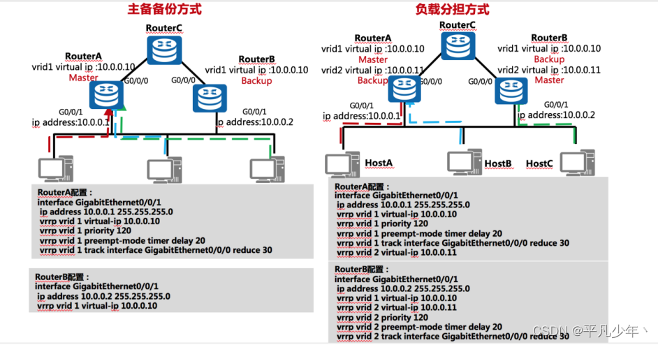
注:正常在三层架构中由于生成树的存在,负载分担方式将可能由于不同vlan根网桥位置不同,导致部分链路阻塞,使得负载分担反而成为累赘; 因此仅建议在直接使用路由器作为网关时,才使用负载分担方式;
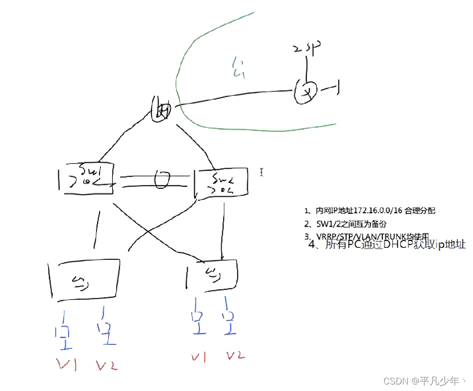
五、实验
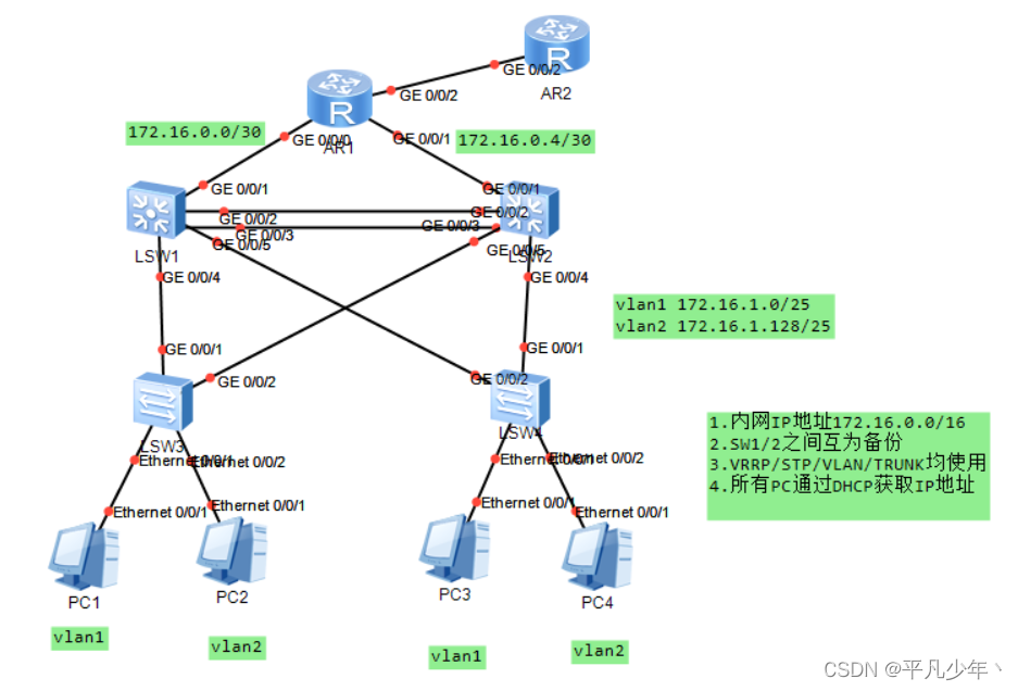
1.交换
需要的技术:VRRP STP VLAN TRUNK Eth-trunk SVI(管理vlan) DHCP
配置顺序:
Eth-trunk    VLAN    TRUNK    STP    SVI    VRRP    DHCP
Eth-trunk
SW1+SW2
interface Eth-Trunk 0
q

interface GigabitEthernet0/0/2
 eth-trunk 0

interface GigabitEthernet0/0/3
 eth-trunk 0
VLAN+TRUNK
SW1+SW2
vlan 2
q

interface Eth-Trunk0
 port link-type trunk
 port trunk allow-pass vlan 2

interface GigabitEthernet0/0/4
 port link-type trunk
 port trunk allow-pass vlan 2

interface GigabitEthernet0/0/5
 port link-type trunk
 port trunk allow-pass vlan 2
SW3+SW4
vlan 2
q

interface GigabitEthernet0/0/1
 port link-type trunk
 port trunk allow-pass vlan 2

interface GigabitEthernet0/0/2
 port link-type trunk
 port trunk allow-pass vlan 2

interface Ethernet0/0/2
 port link-type access
 port default vlan 2
STP
SW1
stp region-configuration
 region-name v1//定义组的名字
 instance 1 vlan 1
 instance 2 vlan 2
 active region-configuration//激活当前配置

stp instance 1 root primary//定义本地为组1的主根
stp instance 2 root secondary//定义本地为组2的备份根
SW2
stp region-configuration
 region-name v1
 instance 1 vlan 1
 instance 2 vlan 2
 active region-configuration

stp instance 1 root secondary
stp instance 2 root primary
SW3+SW4
stp region-configuration
 region-name v1
 instance 1 vlan 1
 instance 2 vlan 2
 active region-configuration

interface Ethernet0/0/1
 stp edged-port enable//进入连接PC的接口,进行端口加速

interface Ethernet0/0/2
 stp edged-port enable
SVI+VRRP
SW1
interface Vlanif1
 ip address 172.16.1.1 255.255.255.128
 vrrp vrid 1 virtual-ip 172.16.1.126//虚拟网关IP
 vrrp vrid 1 priority 120//定义本地为VLAN1的网关
 vrrp vrid 1 track interface GigabitEthernet0/0/1 reduced 30//上行链路追踪

interface Vlanif2
 ip address 172.16.1.129 255.255.255.128
 vrrp vrid 2 virtual-ip 172.16.1.254//VLAN2的备份网关
SW2
interface Vlanif1
 ip address 172.16.1.2 255.255.255.128
 vrrp vrid 1 virtual-ip 172.16.1.126//VLAN1的备份网关

interface Vlanif2
 ip address 172.16.1.130 255.255.255.128
 vrrp vrid 2 virtual-ip 172.16.1.254
 vrrp vrid 2 priority 120//定义本地为VLAN1的网关
 vrrp vrid 2 track interface GigabitEthernet0/0/1 reduced 30//上行链路追踪
DHCP
SW1+SW2
dhcp enable

ip pool v1
 gateway-list 172.16.1.126
 network 172.16.1.0 mask 255.255.255.128
 dns-list 8.8.8.8 114.114.114.114

ip pool v2
 gateway-list 172.16.1.254
 network 172.16.1.128 mask 255.255.255.128
 dns-list 8.8.8.8 114.114.114.114

interface Vlanif1
 dhcp select global

interface Vlanif2
 dhcp select global
2.路由
配置IP地址
交换的最后一步是IP地址,路由的第一步是IP地址
R1
interface GigabitEthernet0/0/0
 ip address 172.16.0.2 255.255.255.252

interface GigabitEthernet0/0/1
 ip address 172.16.0.6 255.255.255.252

interface GigabitEthernet0/0/2
 ip address 12.1.1.1 255.255.255.0
R2
R2表示公网部分
interface GigabitEthernet0/0/2
 ip address 12.1.1.2 255.255.255.0

interface LoopBack0
 ip address 2.2.2.2 255.255.255.0
SW1
由于华为模拟器ensp的软件本身原因,当我们将三层交换机的接口改为三层链路时,并不能在该接口上配置IP地址,因此我们需要用SVI来模拟三层接口。
vlan 100//创建一个用不到的VLAN
q

interface Vlanif100//创建管理VLAN用来模拟三层接口
 ip address 172.16.0.1 255.255.255.252

interface GigabitEthernet0/0/1//将该接口划入VLAN100
 port link-type access
 port default vlan 100
SW2
vlan 100//创建一个用不到的VLAN
q

interface Vlanif100//创建管理VLAN用来模拟三层接口
 ip address 172.16.0.5 255.255.255.252

interface GigabitEthernet0/0/1//将该接口划入VLAN100
 port link-type access
 port default vlan 100
开启OSPF
R1
ospf 1 router-id 1.1.1.1
area 0.0.0.0
network 172.16.0.0 0.0.0.255
SW1
为了减少OSPF的更新量,我们将OSPF划分为两个区域
ospf 1 router-id 2.2.2.2
 silent-interface all//沉默接口用来规避当OSPF运行在SVI接口时,交换机所有和SVI接口在同一VLAN的接口每10s都会收到一个hello包,相当于每10s就会洪泛一次,会对带宽造成很大的占用。故需要使用沉默接口来禁止三层交换机向下发送hello包。
 undo silent-interface Eth-Trunk0//邻居间需要收发hello包
 undo silent-interface Vlanif100
 area 0.0.0.0
  network 172.16.0.1 0.0.0.0
 area 0.0.0.1
  abr-summary 172.16.1.0 255.255.255.0//将区域1的路由汇总为一条给区域0
  network 172.16.1.1 0.0.0.0
  network 172.16.1.129 0.0.0.0
SW2
ospf 1 router-id 3.3.3.3
 silent-interface all
 undo silent-interface Eth-Trunk0
 undo silent-interface Vlanif100
 area 0.0.0.0
  network 172.16.0.5 0.0.0.0
 area 0.0.0.1
  abr-summary 172.16.1.0 255.255.255.0
  network 172.16.1.2 0.0.0.0
  network 172.16.1.130 0.0.0.0
3.上网
R1
ip route-static 0.0.0.0 0.0.0.0 12.1.1.2

ospf 1
 default-route-advertise

acl number 2000
 rule 5 permit source 172.16.0.0 0.0.255.255

interface GigabitEthernet0/0/2
 nat outbound 2000
至此,整个实验已经全部完成,且拥有备份。
总结
三层架构是网络中的一个重要部分,希望本篇博客对大家学习三层架构有所帮助,谢谢大家!
审核编辑:黄飞
-
WLAN三层组网实验解析2024-08-14 1640
-
三层神经网络模型的优缺点2024-07-11 2032
-
javaWeb的MVC三层架构的原理2023-12-03 1971
-
javaweb三层架构和mvc架构2023-11-22 3169
-
浅谈三层架构原理2022-01-16 8082
-
C#最简单的三层架构实例教程2021-05-24 1045
-
交换机的三层网络结构介绍2021-01-09 13713
-
三层交换技术的原理_三层交换技术的基本原理_三层交换技术的工作原理2019-08-20 13141
-
PHP的典型三层架构资料说明2019-02-22 994
-
通信网络三层转发工作原理及案例2018-02-23 24580
-
三层架构和mvc的区别是什么2017-12-27 16177
-
基于三层架构的流程模拟系统的设计与应用_刘红霞2017-01-19 1092
-
企业网络,什么是企业网络2010-03-22 4968
全部0条评论

快来发表一下你的评论吧 !
