
基于LPC1114的学习型红外遥控器程序设计
ARM
描述
本设计就是采用LPC1114+OLED+红外接收头构成一个学习型红外遥控器
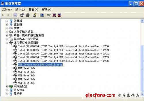
安 装LPCxpress,后插入LPC-Link 自动识别,
系统多出一个

然后打开11XX的例程,正常安装路径在C: xp lpcxpresso_3.1ExamplesLPC1000LPC11xx下
文件名字 LPCXpresso1114_v1.00.zip
然后点击GPIO程序,打开GPIOtest.c开始学习。
发现和普通的 8位机真的相差很多,用了很多类似函数(库)的东西。
别的不管,先来个最简单的闪烁灯。
找到函数
功能:(设置 GPIO口方向),参数(端口号,位,输入或输出(0入1出))
GPIOSetDir( PORT0, 1, 0 );
和
GPIOSetValue()
一 个是设置端口方向,一个是设置输出的值,直接调用就可以了。
下面是我的程序,本人菜鸟一只,程序也不会写,希望大家拍砖的话,别往死里拍, 呵呵。
用的是P32的口。输出1的时候点亮LED。
/*****************************************************************************
* gpiotest.c: main C entry file for NXP LPC11xx Family Microprocessors
*
* Copyright(C) 2008, NXP Semiconductor
* All rights reserved.
*
* History
* 2009.12.07 ver 1.00 Preliminary version, first Release
*
******************************************************************************/
#include "LPC11xx.h" /* LPC11xx Peripheral Registers */
#include "gpio.h"
/*****************************************************************************
** Main Function main()
******************************************************************************/
int main (void)
{
/* Basic chip initialization is taken care of in SystemInit() called
* from the startup code. SystemInit() and chip settings are defined
* in the CMSIS system_
*/
uint32_t a=60000;
GPIOInit();
GPIOSetDir(PORT3,2,1);
while(1)
{
a=160000;
while(a--);
GPIOSetValue(PORT3,2,0);
a=160000;
while(a--);
GPIOSetValue(PORT3,2,1);
}
/* use port0_1 as input event, interrupt test. */
GPIOSetDir( PORT0, 1, 0 );
/* port0_1, single trigger, active high. */
GPIOSetInterrupt( PORT0, 1, 0, 0, 0 );
GPIOIntEnable( PORT0, 1 );
/* use port1_1 as input event, interrupt test. */
GPIOSetDir( PORT1, 1, 0 );
/* port0_1, single edge trigger, active high. */
GPIOSetInterrupt( PORT1, 1, 0, 0, 0 );
GPIOIntEnable( PORT1, 1 );
/* use port2_1 as input event, interrupt test. */
GPIOSetDir( PORT2, 1, 0 );
/* port0_1, single edge trigger, active high. */
GPIOSetInterrupt( PORT2, 1, 0, 0, 0 );
GPIOIntEnable( PORT2, 1 );
/* use port3_1 as input event, interrupt test. */
GPIOSetDir( PORT3, 1, 0 );
/* port0_1, single edge trigger, active high. */
GPIOSetInterrupt( PORT3, 1, 0, 0, 0 );
GPIOIntEnable( PORT3, 1 );
while( 1 );
}
/*********************************************************************************
** End Of File
*********************************************************************************/
使用Keil MDK +ULink2开发LPC11XX
LPCXpresso软件虽然不错,但还是没有常用的KEIL IAR 顺手,怎么说也是用惯了,一狠心,买了个ULINK2,从今天开始使用MDK +ULink2开发LPC1114。
先来介绍一下软件部分, 使用新版本 MDK 410B(www.mcu123.com有下载),无缝 支持LPC1114,安装完软件后,ulink2插到电脑usb口可以自动识别,新建工程,选NXP LPC1114 301 芯片,一路下来没什么问题,关键是ULINK2的配置。
上图。


由于LPC11XX不支持JTAG ,所以只能用图中的SW方式了。
硬件方面,LPC1114的板子需要修改,把LPC-LINK和LPC1114要断开,就是电路图J4的部 分,把PCB划开后,焊上2.54间距排针,
以后想用LPCXpresso软件带LPC-link的话跳线就可以用了。一举两得。
上 图。
在来个图。和闪烁灯的程序。
#include
#include
//---------------------------------------------------------
void sysint(void);
//---------------------------------------------------------
main(void)
{
uint32_t i;
/* Enable AHB clock to the GPIO domain. */
LPC_SYSCON->SYSAHBCLKCTRL |= (1<<6);
/* Set up NVIC when I/O pins are configured as external interrupts. */
NVIC_EnableIRQ(EINT0_IRQn);
NVIC_EnableIRQ(EINT1_IRQn);
NVIC_EnableIRQ(EINT2_IRQn);
NVIC_EnableIRQ(EINT3_IRQn);
LPC_GPIO0->DIR=0xFF;
while(1)
{
LPC_GPIO0->DATA=~LPC_GPIO0->DATA;
i=300000;
while(i--);
}
}
//---------------------------------------------------------
void sysint (void)
{
// uint32_t i;
#ifdef __DEBUG_RAM
LPC_SYSCON->SYSMEMREMAP = 0x1; /* remap to internal RAM */
#else
#ifdef __DEBUG_FLASH
LPC_SYSCON->SYSMEMREMAP = 0x2; /* remap to internal flash */
#endif
#endif
#if (CLOCK_SETUP) /* Clock Setup */
/* bit 0 default is crystal bypass,
bit1 0=0~20Mhz crystal input, 1=15~50Mhz crystal input. */
LPC_SYSCON->SYSOSCCTRL = 0x00;
/* main system OSC run is cleared, bit 5 in PDRUNCFG register */
LPC_SYSCON->PDRUNCFG &= ~(0x1<<5);
/* Wait 200us for OSC to be stablized, no status
indication, dummy wait. */
for ( i = 0; i < 0x100; i++ );
#if (MAIN_PLL_SETUP)
Main_PLL_Setup();
#endif
#endif /* endif CLOCK_SETUP */
/* System clock to the IOCON needs to be enabled or
most of the I/O related peripherals won't work. */
LPC_SYSCON->SYSAHBCLKCTRL |= (1<<16);
return;
}
-
学习型遥控器的设计与实现2023-10-24 690
-
红外学习型遥控器方案说明2022-10-18 5984
-
普通遥控器如何摇身变新型学习型遥控器2018-11-05 3285
-
基于stc89c52单片机的红外学习型遥控器2018-03-15 6919
-
智能学习型红外空调遥控器分析2017-10-16 1786
-
LPC1114开发流程2017-09-22 919
-
如何增加学习型遥控器的学习距离?2017-08-16 2210
-
常用万能学习型红外遥控器设计资料.pdf2017-03-02 14783
-
学习型红外遥控器设计2016-05-01 3357
-
MINI LPC1114学习手册V2.02015-11-02 1178
-
学习型遥控器2012-08-16 7824
-
基于NiosⅡ的红外学习型遥控器设计2010-12-15 3020
-
学习型红外遥控器的设计2010-10-18 1380
-
基于AT89C52的学习型遥控器的设计2009-08-14 850
全部0条评论

快来发表一下你的评论吧 !

