

Ti60F100 内外flash操作方案
描述
有客户认为Ti60F100内部flash容量比较小,只有16Mb,需要外挂flash.这里我们提供了内部flash和外部flash分别操作的方案。
该程序是通过SOC操作4线的外部flash和内部flash.程序先经过外部flash的擦除,写入和读出操作,再经过外部flash的擦除,写入和读出操作,每次读出后会进行数据的比较以判断写入和读出的数据是否一致。
硬件方案如下:
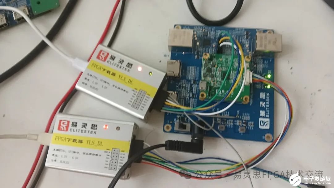
由于使用的RSICV是softjtag操作,所以使用了两个下载器。在硬件设计外外挂一片64Mb的flash。
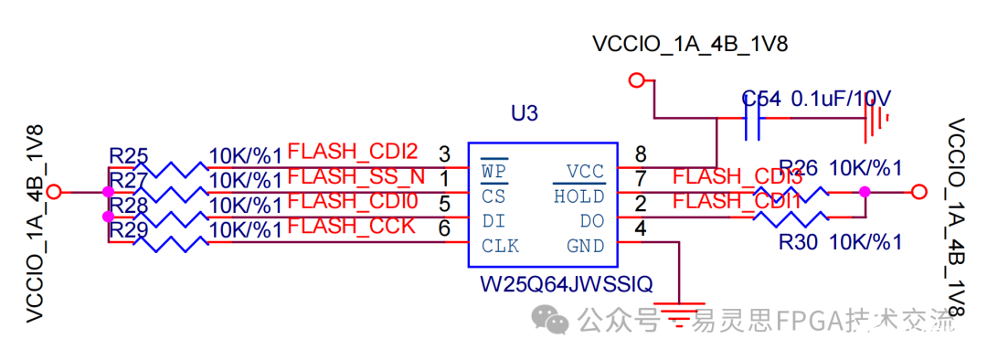
外部flash管脚分配
| flash管脚 | FPGA pin | FPGA name | flash管脚 |
| Flash_cs_n | A4 | GPIOT_P_01 | CS# |
| Flash_cck | J2 | GPIOL_N_01_CCK | SCLK |
| Flash_cdi0 | H2 | GPIOL_P_03_CDI0 | SI |
| Flash_cdi1 | H1 | GPIOL_N_03_CDI1 | SO |
| Flash_cdi2 | G4 | GPIOL_P_05 | WP# |
| Flash_cdi3 | G3 | GPIOL_N_05 | HOLD#RESET# |
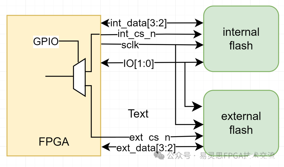
IO的连接方案如下:
内flash与外部flash除片选信号分开外,对于4线flash,IO[3:2]是分开的,其余信号都是共用。SOC操作flash时,我们通过一个GPIO来控制flash的选择
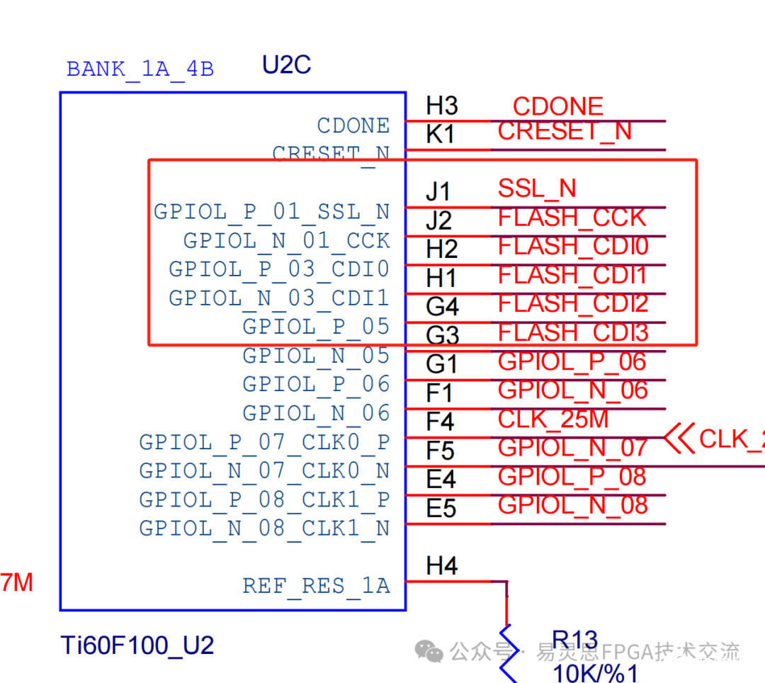
可能会有人有疑问为什么内外flash的管脚能够共用呢?因为内部flash的管脚也拉到GPIO上面的原因。如下图SSL_N,CCK,CDI0,1和都是与内部flash相通的。
外部flash的data2,data3及cs_n的接口配置。
|
IO Configure |
ext_flash_cs_n | ext_flash_data2 | Ext_flash_data3 | ||||
| Mode | outout | inout | Inout | ||||
| I/O Standard | 1.8V lvcmos | 1.8V lvcmos | 1.8V lvcmos | ||||
| IN | OUT | OE | IN | OUT | OE | ||
| Connection Type | normal | normal | - | - | normal | - | - |
| Register Option | register | register | register | register | Register | Register | register |
| Clock Pin Name | soc_clk | soc_clk | soc_clk | soc_clk | Soc_clk | soc_clk | Soc_clk |
| Pull Option | Weak pullup | None | - | - | None | - | |
| Drive Strenght | 12mA | - | 4mA | - | - | 4mA | - |
| Enable Fast Slew Rate | - | - | - | - | - | - | - |
| IO | GPIOT_P_01 | GPIOL_P_05 | GPIOL_N_05 | ||||
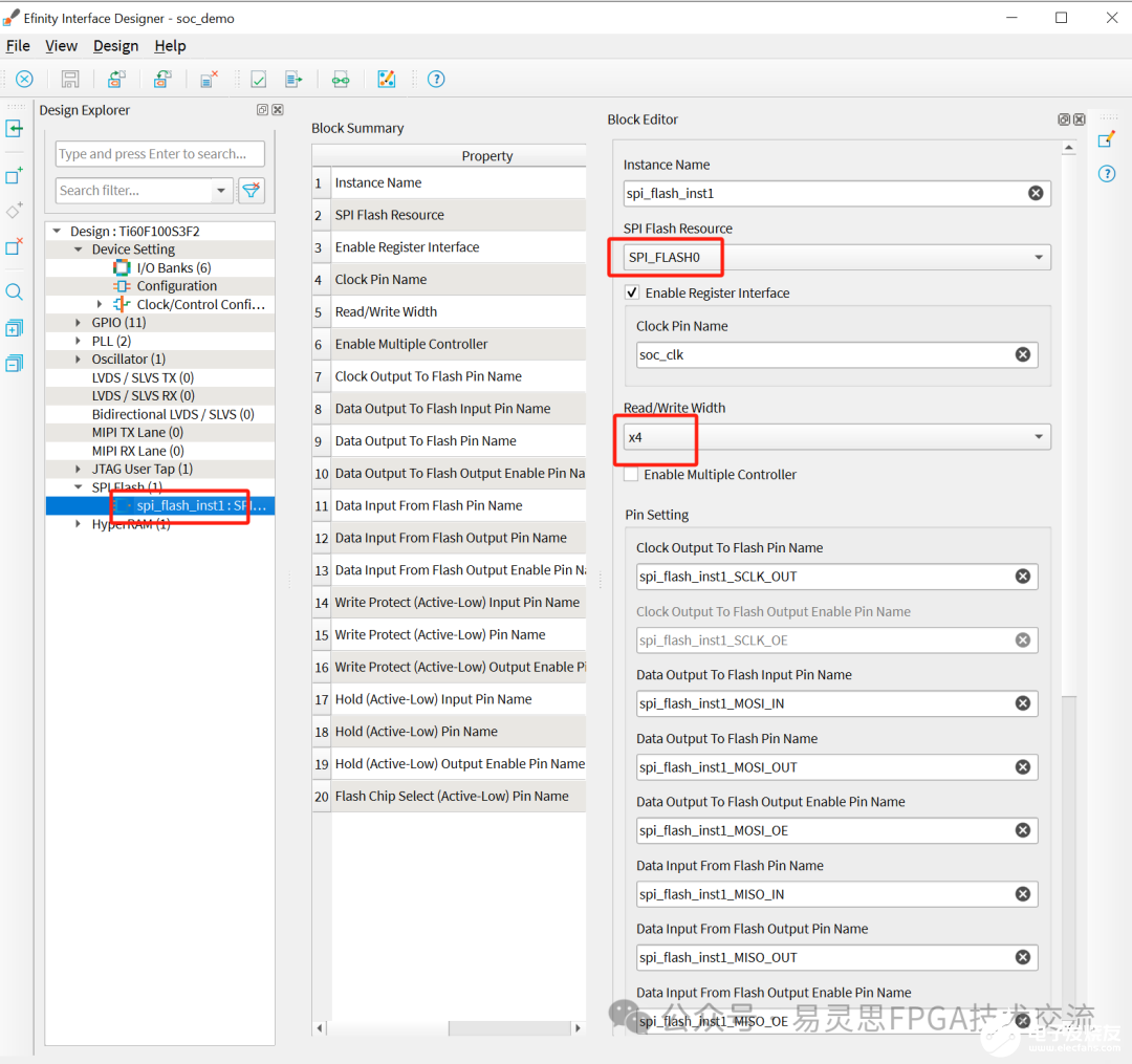
添加SPI flash block,如下图,使能Enable Register Interface, Read/Write Width设置为4。
FPGA通过GPIO来控制操作内部与外部flash,如下图,通过gpio_0来控制选择内部flash还外部flash,int_flash_select为高,表示选择内部flash,为低则选择外部flash。

调试
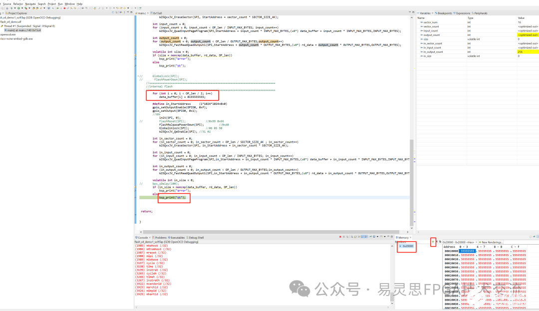
程序经过擦除-->写入-->读出操作后,内存0x20000的数据为下图所示。
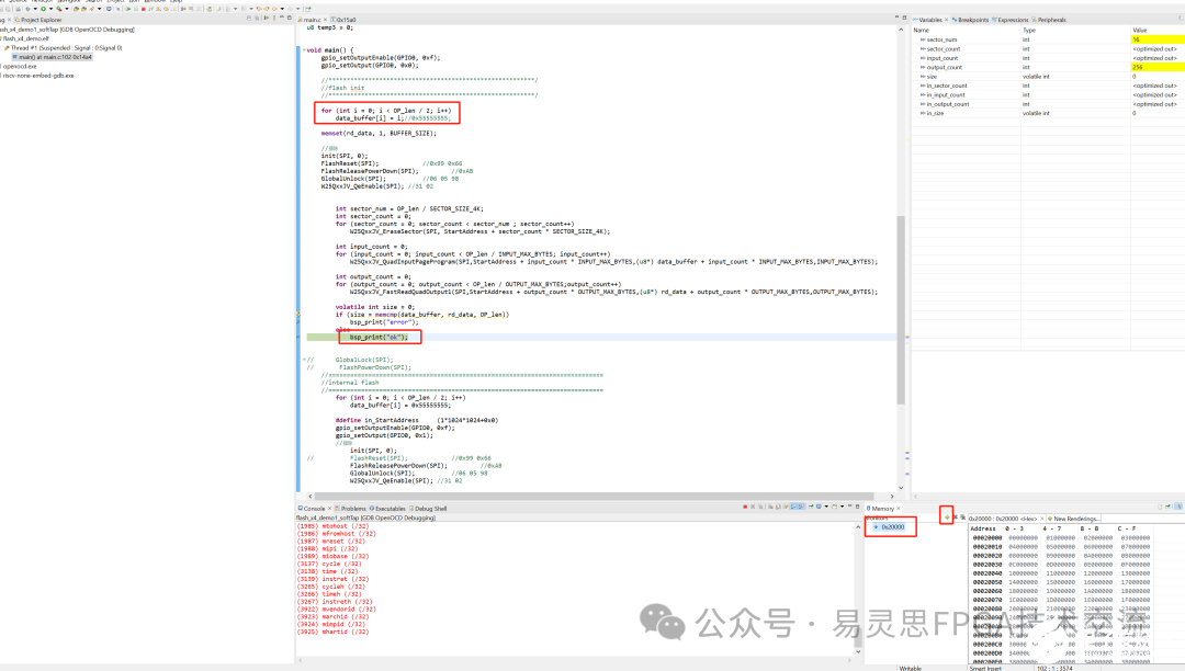
程序经过擦除-->写入-->读出操作后,内存0x20000的数据为下图所示。
- 相关推荐
- 热点推荐
- FlaSh
-
采用易灵思Ti60F100的Ti60F100I3评估板详解2025-01-22 2487
-
FLASH擦写操作非法操作解决方案-HK32F030M应用笔记(二十四)2023-09-18 1453
-
易灵思Ti60F100驱动LCD屏案例2023-07-10 1730
-
Flash基本操作——Flash基础(1)#多媒体技术未来加油dz 2023-05-24
-
PCA7412F-100/PCA7412L-100/PCA7412G-100/PCA7413F-80 用户手册(PROM Adapter for M16C/60 Series)2023-04-18 400
-
求一种Ti60F100高速IO实现HDMI环出方案2023-03-09 3906
-
Ti60F100用片内flash启动RISCV程序不能成功的解决办法2023-02-15 2598
-
STM32F1 使用easyflash操作片内flash2021-12-09 868
-
STM32F103:内部Flash的读写2021-12-01 1587
-
stm32 HAL库Flash该如何去操作2021-08-19 1400
-
PWD13F60 STMicroelectronics PWD13F60栅极驱动器2020-10-30 637
-
MSP430F169中对Flash的信息段A整段进行读写操作2018-05-03 1229
-
TI_C2000系列DSP_Flash烧写解决方案2017-10-13 1435
-
盛群再推Enhanced Flash MCU系列新产品HT68F60与HT66F602011-12-22 3059
全部0条评论

快来发表一下你的评论吧 !

