
深度解析CORDIC算法原理
描述
CORDIC算法详解
1 平面坐标系旋转
CORDIC算法的思想是通过迭代的方法,使得累计旋转过的角度的和无限接近目标角度。它是一种数值计算逼近的方法,运算只有移位和加减。
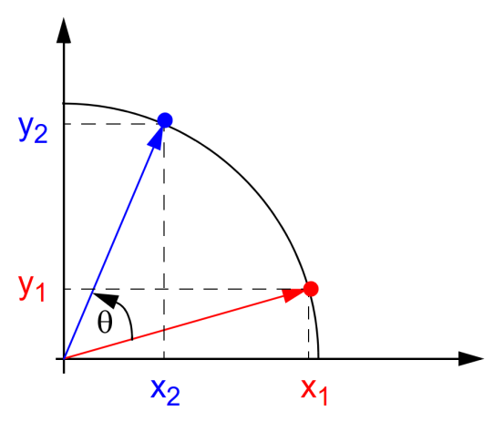
通过圆坐标系可以了解CORDIC算法的基本思想,如图1所示,初始向量 ( x 1 , y 1 ) left( x_{1},y_{1} ight) (x1,y1)旋转 θ heta θ角度之后得到向量 ( x 2 , y 2 ) left( x_{2},y_{2} ight) (x2,y2),两者之间满足(公式1)关系。

图1 CORDIC算法原理示意图
{ x 2 = x 1 cos θ n − y 1 sin θ n y 2 = y 1 cos θ n − x 1 sin θ n left{ egin{matrix} x_{2} = x_{1} cos heta_{n} - y_{1} sin heta_{n} \ y_{2} = y_{1} cos heta_{n} - x_{1}sin heta_{n} \ end{matrix} ight. {x2=x1cosθn−y1sinθny2=y1cosθn−x1sinθn
通过提取因数 cos θ cos heta cosθ,方程式可以改写成下面的形式:
x 2 = x 1 cos θ − y 1 sin θ = cos θ ( x 1 − y 1 tan θ ) y 2 = y 1 cos θ − x 1 sin θ = cos θ ( y 1 + x 1 tan θ ) egin{matrix} x_{2} = x_{1} cos heta - y_{1} sin heta = cos hetaleft( x_{1} - y_{1} an heta ight) \ y_{2} = y_{1} cos heta - x_{1}sin heta = cos hetaleft( y_{1} + x_{1} an heta ight) \ end{matrix} x2=x1cosθ−y1sinθ=cosθ(x1−y1tanθ)y2=y1cosθ−x1sinθ=cosθ(y1+x1tanθ)
2 伪旋转
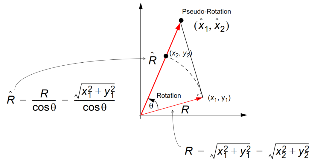
如果去掉 cos θ cos heta cosθ,我们可以的到伪旋转方程式(公式3),即旋转的角度是正确的,但是 x x x, y y y的值增加了 cos − 1 θ cos^{- 1} heta cos−1θ倍,由于 cos − 1 θ > 1 cos^{- 1} heta > 1 cos−1θ>1,所以模值变大。这里并不能通过数学方法去除 cos θ cos heta cosθ项,但是可以化简坐标平面旋转的计算。
x ^ 2 = x 1 − y 1 tan θ y ^ 2 = y 1 + x 1 tan θ egin{matrix} {widehat{x}}_{2} = x_{1} - y_{1} an heta \ {widehat{y}}_{2} = y_{1} + x_{1} an heta \ end{matrix} x 2=x1−y1tanθy 2=y1+x1tanθ

图2 去除 cos θ cos heta cosθ后伪坐标系
3 CORDIC方法
这里为了便于硬件的计算,采用迭代的思想,旋转角度 θ heta θ可以通过若干步实现,每一步旋转一个角度 θ i heta^{i} θi。并且约定每一次旋转的角度的正切值为2的倍数,即 tan θ i = 2 − i { an heta^{i} = 2}^{- i} tanθi=2−i。下面表格是用于CORDIC算法中每个迭代i的旋转角度。这样,乘以正切值就可以变成移位操作。
表1 迭代角度 θ i heta^{i} θi正切值
| i i i | θ i heta^{i} θi(degree) | tan θ i = 2 − i { an heta^{i} = 2}^{- i} tanθi=2−i |
|---|---|---|
| 0 | 45.0 | 1 |
| 1 | 26.555051177 | 0.5 |
| 2 | 14.036243467 | 0.25 |
| 3 | 7.125016348 | 0.125 |
| 4 | 3.576334374 | 0.0625 |
4 角度累加器
引入控制算子 d i d_{i} di,用于确定旋转的方向。其中第i步顺时针旋转时 d i = − 1 d_{i} = - 1 di=−1,逆时针旋转 d i = 1 d_{i} = 1 di=1。前面的伪旋转坐标方程现在可以表示为:
x i + 1 = x i − d i 2 − i y i y i + 1 = y i + d i 2 − i x i egin{matrix} x_{i + 1} = x_{i} - {d_{i}2^{- i} y}_{i} \ y_{i + 1} = y_{i} + {d_{i} 2^{- i} x}_{i} \ end{matrix} xi+1=xi−di2−iyiyi+1=yi+di2−ixi
这里,我们引入第三个方程,被称为角度累加器,用来在每次迭代过程中追踪累加的旋转角度,表示第n次旋转后剩下未旋转的角度,定义为
z i + 1 = z i − d i θ i z_{i + 1} = z_{i} - d_{i} heta^{i} zi+1=zi−diθi ,其中 d i = ± 1 d_{i} = pm 1 di=±1
5 移位-加法算法
因此,原始的算法现在已经被简化为使用向量的伪旋转方程式(公式6)来表示迭代(移位-加法)算法。
2次移位;
( 2 − i 2^{- i} 2−i用移位实现,每右移n位就把原来数值乘以2的-i次方了)
1次查找表;(每一次迭代都会有一个固定角度 θ i heta^{i} θi的累加,这个角度是 2 − i 2^{- i} 2−i对应的角度值,使用查表实现。 θ i = arc tan 2 − i heta^{i} = { ext{arc} an}2^{- i} θi=arctan2−i)
3次加法;(x,y,z的累加,共三次)
x i + 1 = x i − d i 2 − i y i y i + 1 = y i + d i 2 − i x i z i + 1 = z i − d i θ i egin{matrix} x_{i + 1} = x_{i} - {d_{i} 2^{- i} y}_{i} \ y_{i + 1} = y_{i} + {d_{i} 2^{- i} x}_{i} \ z_{i + 1} = z_{i} - d_{i} heta^{i} \ end{matrix} xi+1=xi−di2−iyiyi+1=yi+di2−ixizi+1=zi−diθi
6 伸缩因子
当简化算法以伪旋转时, cos θ cos heta cosθ项被忽略,这样 ( x n , y n ) left( x_{n},y_{n} ight) (xn,yn)就被伸缩了 K n K_{n} Kn倍。如果迭代次数已知,可以预先计算伸缩因子 K n K_{n} Kn。同样 1 / K n 1/K_{n} 1/Kn也可被预先计算以得到 ( x n , y n ) left( x_{n},y_{n} ight) (xn,yn)的真值。
K n = ∏ n 1 cos θ i = ∏ n ( 1 + 2 − 2 i ) K_{n} = prod_{n}^{}frac{1}{cos heta^{i}} = prod_{n}^{}left( sqrt{1 + 2^{- 2i}} ight) Kn=n∏cosθi1=n∏(1+2−2i )
这里 K n − > 1.64676 K_{n} - > 1.64676 Kn−>1.64676,当 n − > ∞ n - > infty n−>∞
1 / K n − > 0.607253 1/K_{n} - > 0.607253 1/Kn−>0.607253,当 n − > ∞ n - > infty n−>∞
7 旋转模式
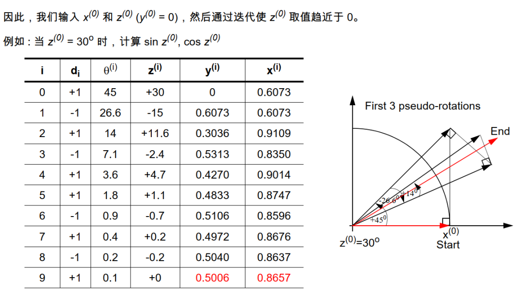
CORDIC方法有两种模式,旋转模式和向量模式。工作模式决定了控制算子 d i d_{i} di的条件。在旋转模式中,旋转剩余角度初始变量 z 0 = θ z_{0} = heta z0=θ,经过n次旋转后,使 z 0 = 0 z_{0} = 0 z0=0。整个旋转过程可以表示为一系列旋转角度不断偏摆,从而逼近所需旋转角度的迭代过程。n次迭代后可以得到:
x n = K n ( x 0 cos z 0 − y 0 sin z 0 ) y n = K n ( y 0 cos z 0 + x 0 sin z 0 ) z n = 0 egin{matrix} x_{n} = K_{n}left( x_{0} cos z_{0} - y_{0} sin z_{0} ight) \ y_{n} = K_{n}left( y_{0} cos z_{0} + x_{0} sin z_{0} ight) \ z_{n} = 0 \ end{matrix} xn=Kn(x0cosz0−y0sinz0)yn=Kn(y0cosz0+x0sinz0)zn=0
通过设置 x 0 = 1 / K n = 0.6073 x_{0} = 1/K_{n} = 0.6073 x0=1/Kn=0.6073和 y 0 = 0 y_{0} = 0 y0=0可以计算 cos z 0 cos z_{0} cosz0和 sin z 0 sin z_{0} sinz0。分析可知CORDIC算法在圆周系统旋转模式下可以用来计算一个输入角的正弦值、余弦值。
x n = K n ( x 0 cos z 0 − y 0 sin z 0 ) = cos θ y n = K n ( y 0 cos z 0 + x 0 sin z 0 ) = sin θ egin{matrix} x_{n} = K_{n}left( x_{0} cos z_{0} - y_{0} sin z_{0} ight) = cos heta \ y_{n} = K_{n}left( y_{0} cos z_{0} + x_{0} sin z_{0} ight) = sin heta \ end{matrix} xn=Kn(x0cosz0−y0sinz0)=cosθyn=Kn(y0cosz0+x0sinz0)=sinθ

图 3 旋转模式角度逼近
8 象限判断
对于任意角度 θ heta θ,都可以通过旋转一系列小角度来i完成。第一次迭代旋转45°,第二次迭代旋转26.6°,第三次迭代旋转14°。很显然,每次旋转的方向都影响到最终的累计角度。在-99.7°< θ heta θ< 99.7°的范围内任意角度都可以旋转。对于该角度范围之外的角度,可以通过三角函数等式转化成该范围内的角度。因此设计时通常把角度 θ heta θ转化到第一象限角,根据 θ heta θ所在的圆坐标系象限获得 x n x_{n} xn和 y n y_{n} yn。
9溢出处理
通过表2可以看出,把初始 θ heta θ角度设置为90°,由于 x 0 x_{0} x0赋的初值存在误差(一般是偏大),最终获得的 x n x_{n} xn和 y n y_{n} yn是有可能大于1的。所以设计时需要做溢出保护。或者把 x 0 x_{0} x0初值减小,这可能会牺牲精度。
表2 θ heta θ接近90°数据溢出
| i | d | theta | z | y | x | SIN | COS |
|---|---|---|---|---|---|---|---|
| 0 | 1 | 45 | 89.9970 | 0 | 0.6073 | 0 | 19900 |
| 1 | 1 | 26.6 | 44.9970 | 0.6073 | 0.6073 | 19900 | 19900 |
| 2 | 1 | 14 | 18.3970 | 0.9110 | 0.3037 | 29850 | 9950 |
| 3 | 1 | 7.1 | 4.3970 | 0.9869 | 0.0759 | 32338 | 2488 |
| 4 | -1 | 3.6 | -2.7030 | 0.9964 | -0.0474 | 32648 | -1555 |
| 5 | 1 | 1.8 | 0.8970 | 0.9993 | 0.0148 | 32746 | 486 |
| 6 | -1 | 0.9 | -0.9030 | 0.9998 | -0.0164 | 32761 | -537 |
| 7 | -1 | 0.4 | -0.0030 | 1.0000 | -0.0008 | 32769 | -26 |
| 8 | 1 | 0.2 | 0.3970 | 1.0000 | 0.0070 | 32769 | 230 |
| 9 | 1 | 0.1 | 0.1970 | 1.0001 | 0.0031 | 32770 | 102 |
| 10 | 1 | 0.056 | 0.0970 | 1.0001 | 0.0012 | 32770 | 38 |
| 11 | 1 | 0.027 | 0.0410 | 1.0001 | 0.0002 | 32771 | 6 |
10 Verilog代码实现
CORDIC算法代码
module MyCORDIC(
input clk,
input rst_n,
input  [15:0]theta,
output reg [15:0]sin_theta,
output reg [15:0]cos_theta
);

parameter Kn  = 'd19898;    // 0.607253*2^15
parameter iKn = 'd53961;    // 1.64676*2^15

parameter arctan_0 = 8192    ;  // arctan(1/2)
parameter arctan_1 = 4836    ;  // arctan(1/2^1)
parameter arctan_2 = 2555    ;  // arctan(1/2^2)
parameter arctan_3 = 1297    ;  // arctan(1/2^3)
parameter arctan_4 = 651     ;  // arctan(1/2^4)
parameter arctan_5 = 326     ;  // arctan(1/2^5)
parameter arctan_6 = 163     ;  // arctan(1/2^6)
parameter arctan_7 = 81      ;  // arctan(1/2^7)
parameter arctan_8 = 41      ;  // arctan(1/2^8)
parameter arctan_9 = 20      ;  // arctan(1/2^9)
parameter arctan_10 = 10     ;  // arctan(1/2^10)
parameter arctan_11 = 5      ;  // arctan(1/2^11)

reg signed [15:0] x [11:0];
reg signed [15:0] y [11:0];
reg signed [15:0] z [11:0];

wire [15:0]x_tmp;
wire [15:0]y_tmp;

reg signed [15:0]theta_1;
wire [2:0] Quadrant;//theta角所在的象限

// 象限判断
assign Quadrant = theta[15:14] + 1;

always@(*)
begin
begin
theta_1 <= {2'b00,theta[13:0]};
if(Quadrant==1)
begin
theta_1 <= theta;
end
else if(Quadrant==2)
begin
theta_1 <= 32768 - theta;
end
else if(Quadrant==3)
begin
theta_1 <= theta - 32768;
end
else if(Quadrant==4)
begin
theta_1 <= 65536 - theta;
end
end
end

always@(posedge clk or negedge rst_n)
begin
if(!rst_n)
begin
x[0] <= 16'd0;
y[0] <= 16'd0;
z[0] <= 16'd0;
end
else
begin
x[0] <= Kn;
y[0] <= 16'd0;
z[0] <= theta_1;
end
end

always@(posedge clk or negedge rst_n) // i=0
begin
if(!rst_n)
begin
x[1] <= 16'd0;
y[1] <= 16'd0;
z[1] <= 16'd0;
end
else
begin
if(z[0][15]) // 剩余角度为负数,顺时针旋转,d=-1
begin
x[1] <= x[0] + y[0];
y[1] <= y[0] - x[0];
z[1] <= z[0] + arctan_0;
end          // 剩余角度为正数,顺时针旋转,d=+1
else
begin
x[1] <= x[0] - y[0];
y[1] <= y[0] + x[0];
z[1] <= z[0] - arctan_0;
end
end
end

// >>>符号表示算术右移,不改变符号位
always@(posedge clk or negedge rst_n) // i=1
begin
if(!rst_n)
begin
x[2] <= 16'd0;
y[2] <= 16'd0;
z[2] <= 16'd0;
end
else
begin
if(z[1][15]) // 剩余角度为负数,顺时针旋转,d=-1
begin
x[2] <= x[1] + (y[1] >>> 1);
y[2] <= y[1] - (x[1] >>> 1);
z[2] <= z[1] + arctan_1;
end          // 剩余角度为正数,逆时针旋转,d=+1
else
begin
x[2] <= x[1] - (y[1] >>> 1);
y[2] <= y[1] + (x[1] >>> 1);
z[2] <= z[1] - arctan_1;
end
end
end

always@(posedge clk or negedge rst_n) // i=2
begin
if(!rst_n)
begin
x[3] <= 16'd0;
y[3] <= 16'd0;
z[3] <= 16'd0;
end
else
begin
if(z[2][15]) // 剩余角度为负数,顺时针旋转,d=-1
begin
x[3] <= x[2] + (y[2] >>> 2);
y[3] <= y[2] - (x[2] >>> 2);
z[3] <= z[2] + arctan_2;
end          // 剩余角度为正数,逆时针旋转,d=+1
else
begin
x[3] <= x[2] - (y[2] >>> 2);
y[3] <= y[2] + (x[2] >>> 2);
z[3] <= z[2] - arctan_2;
end
end
end

always@(posedge clk or negedge rst_n) // i=3
begin
if(!rst_n)
begin
x[4] <= 16'd0;
y[4] <= 16'd0;
z[4] <= 16'd0;
end
else
begin
if(z[3][15]) // 剩余角度为负数,顺时针旋转,d=-1
begin
x[4] <= x[3] + (y[3] >>> 3);
y[4] <= y[3] - (x[3] >>> 3);
z[4] <= z[3] + arctan_3;
end          // 剩余角度为正数,逆时针旋转,d=+1
else
begin
x[4] <= x[3] - (y[3] >>> 3);
y[4] <= y[3] + (x[3] >>> 3);
z[4] <= z[3] - arctan_3;
end
end
end


always@(posedge clk or negedge rst_n) // i=4
begin
if(!rst_n)
begin
x[5] <= 16'd0;
y[5] <= 16'd0;
z[5] <= 16'd0;
end
else
begin
if(z[4][15]) // 剩余角度为负数,顺时针旋转,d=-1
begin
x[5] <= x[4] + (y[4] >>> 4);
y[5] <= y[4] - (x[4] >>> 4);
z[5] <= z[4] + arctan_4;
end          // 剩余角度为正数,逆时针旋转,d=+1
else
begin
x[5] <= x[4] - (y[4] >>> 4);
y[5] <= y[4] + (x[4] >>> 4);
z[5] <= z[4] - arctan_4;
end
end
end

always@(posedge clk or negedge rst_n) // i=5
begin
if(!rst_n)
begin
x[6] <= 16'd0;
y[6] <= 16'd0;
z[6] <= 16'd0;
end
else
begin
if(z[5][15]) // 剩余角度为负数,顺时针旋转,d=-1
begin
x[6] <= x[5] + (y[5] >>> 5);
y[6] <= y[5] - (x[5] >>> 5);
z[6] <= z[5] + arctan_5;
end          // 剩余角度为正数,逆时针旋转,d=+1
else
begin
x[6] <= x[5] - (y[5] >>> 5);
y[6] <= y[5] + (x[5] >>> 5);
z[6] <= z[5] - arctan_5;
end
end
end

always@(posedge clk or negedge rst_n) // i=6
begin
if(!rst_n)
begin
x[7] <= 16'd0;
y[7] <= 16'd0;
z[7] <= 16'd0;
end
else
begin
if(z[6][15]) // 剩余角度为负数,顺时针旋转,d=-1
begin
x[7] <= x[6] + (y[6] >>> 6);
y[7] <= y[6] - (x[6] >>> 6);
z[7] <= z[6] + arctan_6;
end          // 剩余角度为正数,逆时针旋转,d=+1
else
begin
x[7] <= x[6] - (y[6] >>> 6);
y[7] <= y[6] + (x[6] >>> 6);
z[7] <= z[6] - arctan_6;
end
end
end


always@(posedge clk or negedge rst_n) // i=7
begin
if(!rst_n)
begin
x[8] <= 16'd0;
y[8] <= 16'd0;
z[8] <= 16'd0;
end
else
begin
if(z[7][15]) // 剩余角度为负数,顺时针旋转,d=-1
begin
x[8] <= x[7] + (y[7] >>> 7);
y[8] <= y[7] - (x[7] >>> 7);
z[8] <= z[7] + arctan_7;
end          // 剩余角度为正数,逆时针旋转,d=+1
else
begin
x[8] <= x[7] - (y[7] >>> 7);
y[8] <= y[7] + (x[7] >>> 7);
z[8] <= z[7] - arctan_7;
end
end
end

always@(posedge clk or negedge rst_n) // i=8
begin
if(!rst_n)
begin
x[9] <= 16'd0;
y[9] <= 16'd0;
z[9] <= 16'd0;
end
else
begin
if(z[8][15]) // 剩余角度为负数,顺时针旋转,d=-1
begin
x[9] <= x[8] + (y[8] >>> 8);
y[9] <= y[8] - (x[8] >>> 8);
z[9] <= z[8] + arctan_8;
end          // 剩余角度为正数,逆时针旋转,d=+1
else
begin
x[9] <= x[8] - (y[8] >>> 8);
y[9] <= y[8] + (x[8] >>> 8);
z[9] <= z[8] - arctan_8;
end
end
end

always@(posedge clk or negedge rst_n) // i=9
begin
if(!rst_n)
begin
x[10] <= 16'd0;
y[10] <= 16'd0;
z[10] <= 16'd0;
end
else
begin
if(z[9][15]) // 剩余角度为负数,顺时针旋转,d=-1
begin
x[10] <= x[9] + (y[9] >>> 9);
y[10] <= y[9] - (x[9] >>> 9);
z[10] <= z[9] + arctan_9;
end          // 剩余角度为正数,逆时针旋转,d=+1
else
begin
x[10] <= x[9] - (y[9] >>> 9);
y[10] <= y[9] + (x[9] >>> 9);
z[10] <= z[9] - arctan_9;
end
end
end

always@(posedge clk or negedge rst_n) // i=10
begin
if(!rst_n)
begin
x[11] <= 16'd0;
y[11] <= 16'd0;
z[11] <= 16'd0;
end
else
begin
if(z[10][15]) // 剩余角度为负数,顺时针旋转,d=-1
begin
x[11] <= x[10] + (y[10] >>> 10);
y[11] <= y[10] - (x[10] >>> 10);
z[11] <= z[10] + arctan_10;
end          // 剩余角度为正数,逆时针旋转,d=+1
else
begin
x[11] <= x[10] - (y[10] >>> 10);
y[11] <= y[10] + (x[10] >>> 10);
z[11] <= z[10] - arctan_10;
end
end
end

// 溢出判断
assign x_tmp = x[11][15]==1 ? 16'h7FFF : x[11];
assign y_tmp = y[11][15]==1 ? 16'h7FFF : y[11];
//assign x_tmp = x[11];
//assign y_tmp = y[11];

always@(posedge clk or negedge rst_n) // i=11
begin
if(!rst_n)
begin
sin_theta <= 16'd0;
cos_theta <= 16'd0;
end
else
begin
if(Quadrant == 3'd1)
begin
sin_theta <= y_tmp;
cos_theta <= x_tmp;
end
else if(Quadrant == 3'd2)
begin
sin_theta <= y_tmp;
cos_theta <= -x_tmp;
end
else if(Quadrant == 3'd3)
begin
sin_theta <= -y_tmp;
cos_theta <= -x_tmp;
end
else if(Quadrant == 3'd4)
begin
sin_theta <= -y_tmp;
cos_theta <= x_tmp;
end
else
begin
sin_theta <= sin_theta;
cos_theta <= cos_theta;
end
end
end
endmodule
testbench文件
`timescale 1 ns/ 1 ns

module MyCORDIC_tb(
);

integer i;

reg clk,rst_n;
reg [15:0] theta,theta_n;
wire [15:0]sin_theta,cos_theta;

reg [15:0] cnt,cnt_n;

MyCORDIC u0(
.clk       (clk      ),
.rst_n     (rst_n    ),
.theta     (theta    ),
.sin_theta (sin_theta),
.cos_theta (cos_theta)
);

initial
begin
    #0 clk = 1'b0;
    #10 rst_n = 1'b0;
    #10 rst_n = 1'b1;
    #10000000 $stop;
end

initial
begin
    #0 theta = 16'd20;
   for(i=0;i<10000;i=i+1)
begin
#400;
theta <= theta + 16'd200;
end
end

always #10
begin
    clk = ~clk;
end

endmodule
ModelSim仿真

审核编辑:黄飞
-
CORDIC理论分析2010-07-28 2198
-
基于改进的CORDIC算法的FFT复乘及其FPGA实现2011-07-11 4494
-
CORDIC算法求助2015-07-11 4615
-
FPGA设计中必须掌握的Cordic算法2019-09-19 6229
-
高性能HPOR CORDIC算法及实现2009-12-15 774
-
基于CORDIC算法的载波同步锁相环设计2010-12-15 807
-
基于CORDIC算法2FSK调制器的FPGA设计2011-05-31 2216
-
双模式CORDIC算法的FPGA实现2011-06-27 1221
-
cordic算法verilog实现(简单版)2017-02-11 3528
-
高速低功耗CORDIC算法的研究与实现2017-11-16 1142
-
基于FPGA的Cordic算法实现的设计与验证2018-07-03 3410
-
基于CORDIC的高速Sobel算法实现2018-10-05 4095
-
CORDIC算法的原理及具体应用2019-11-13 7339
-
一文带你们了解什么是CORDIC算法2021-04-11 16972
-
CORDIC算法简介2023-03-28 3310
全部0条评论

快来发表一下你的评论吧 !

