

 e2studio开发三轴加速度计LIS2DW12(2)----基于中断信号获取加速度数据
描述
概述
本文将介绍实时获取和处理加速度数据。程序的核心流程包括初始化硬件接口、配置加速度计的参数,以及通过轮询检查中断信号来不断读取加速度数据。
最近在弄ST和瑞萨RA的课程,需要样片的可以加群申请:615061293 。
视频教学
[https://www.bilibili.com/video/BV1Wa4y117pq/]
样品申请
[https://www.wjx.top/vm/OhcKxJk.aspx#]
源码下载
[https://download.csdn.net/download/qq_24312945/88735785]
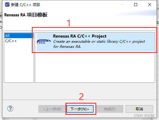
新建工程
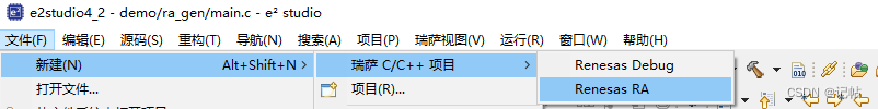
工程模板
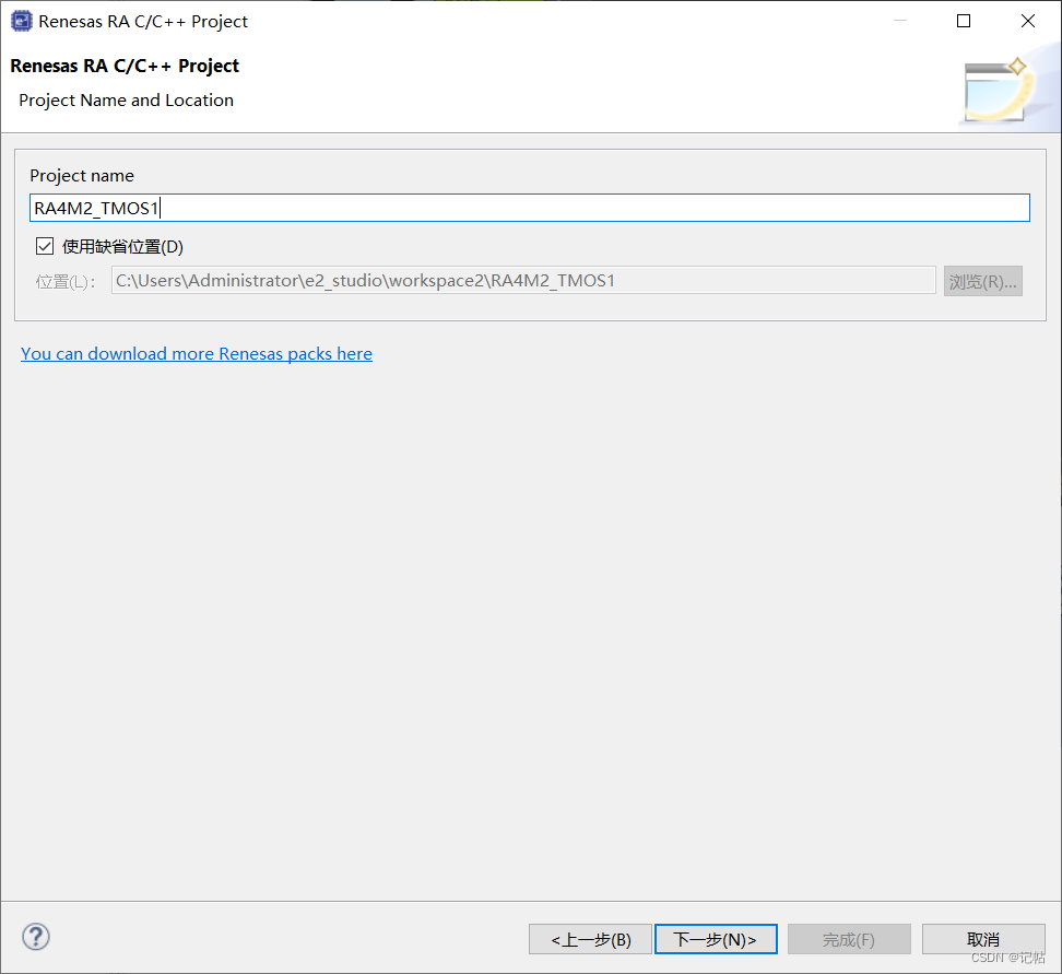
保存工程路径
芯片配置
本文中使用R7FA4M2AD3CFL来进行演示。 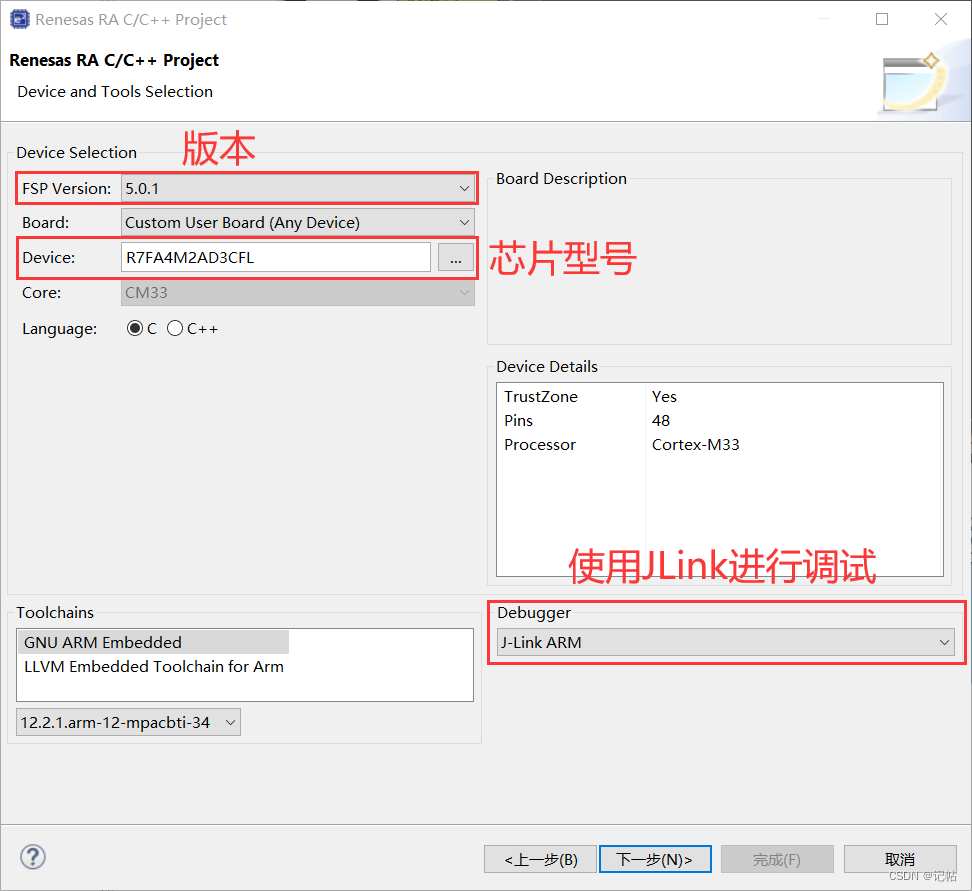
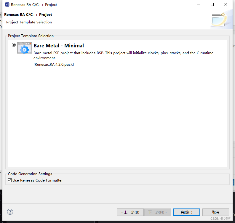
工程模板选择
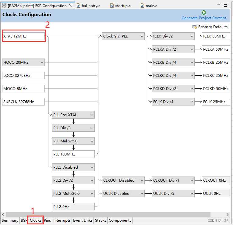
时钟设置
开发板上的外部高速晶振为12M.
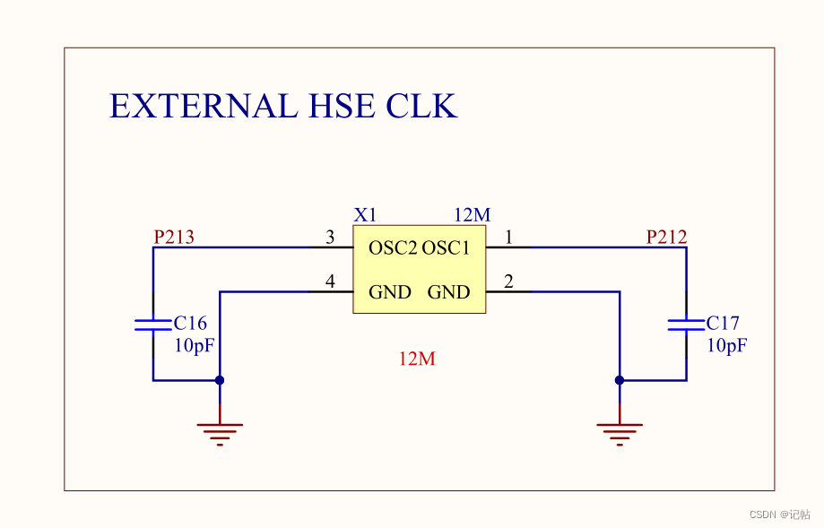 需要修改XTAL为12M。
UART配置
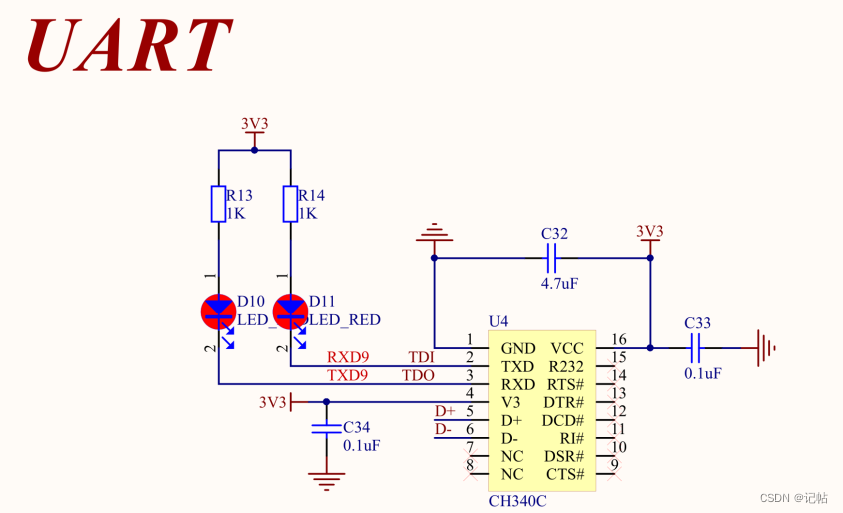 点击Stacks->New Stack->Driver->Connectivity -> UART Driver on r_sci_uart。
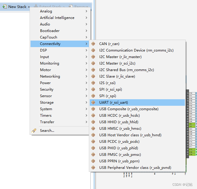
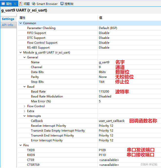
UART属性配置
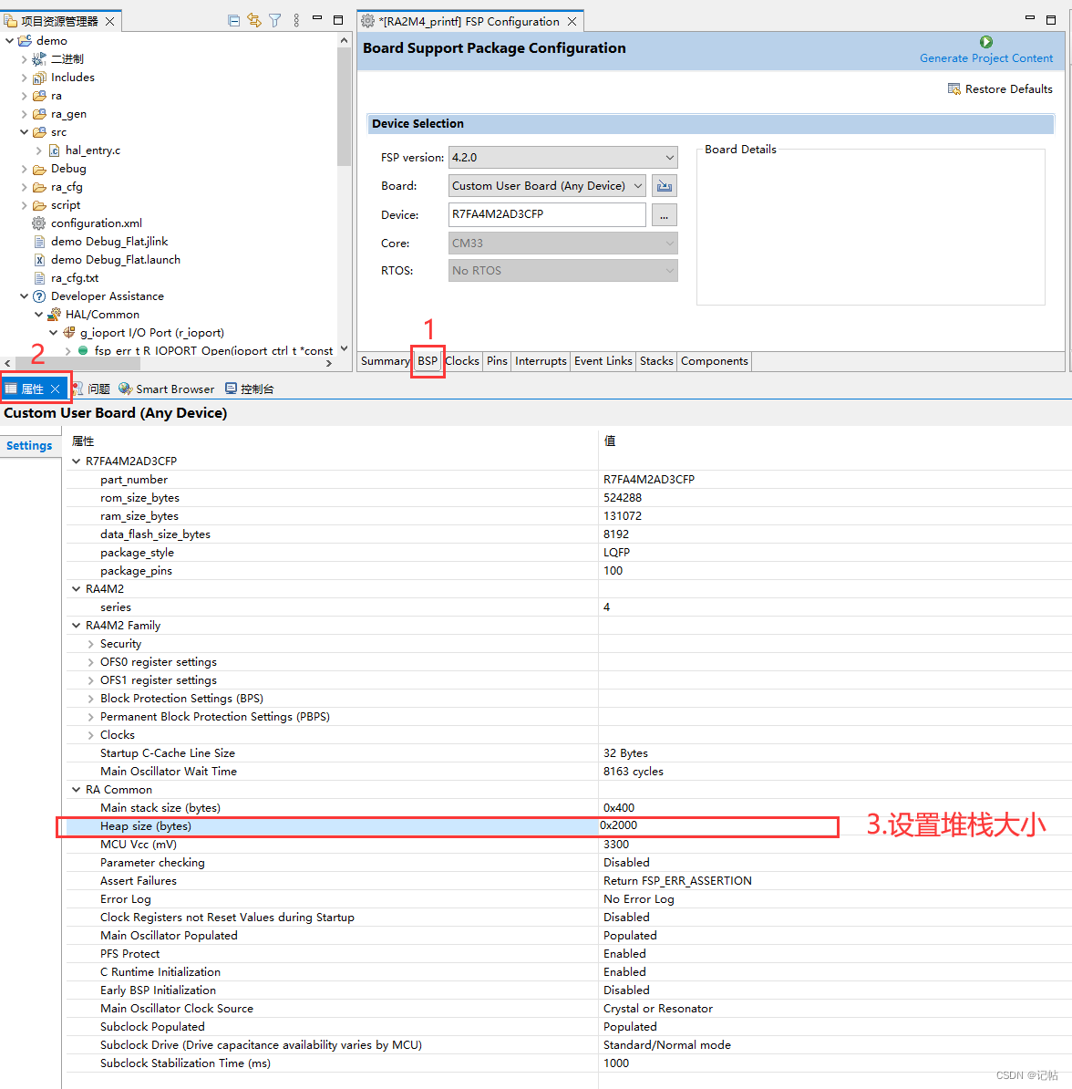
设置e2studio堆栈
printf函数通常需要设置堆栈大小。这是因为printf函数在运行时需要使用栈空间来存储临时变量和函数调用信息。如果堆栈大小不足,可能会导致程序崩溃或不可预期的行为。
printf函数使用了可变参数列表,它会在调用时使用栈来存储参数,在函数调用结束时再清除参数,这需要足够的栈空间。另外printf也会使用一些临时变量,如果栈空间不足,会导致程序崩溃。
因此,为了避免这类问题,应该根据程序的需求来合理设置堆栈大小。
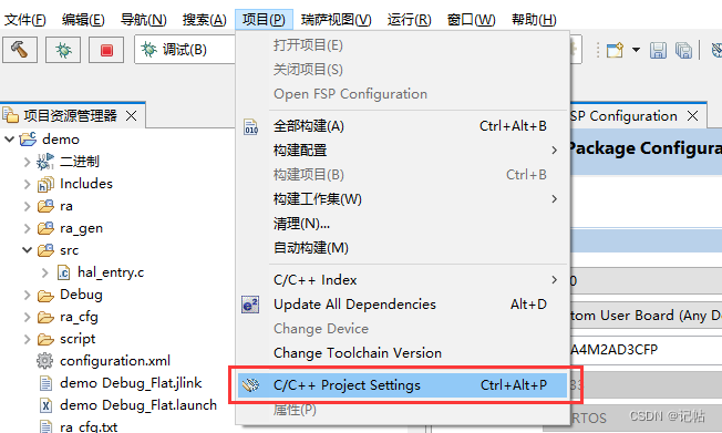
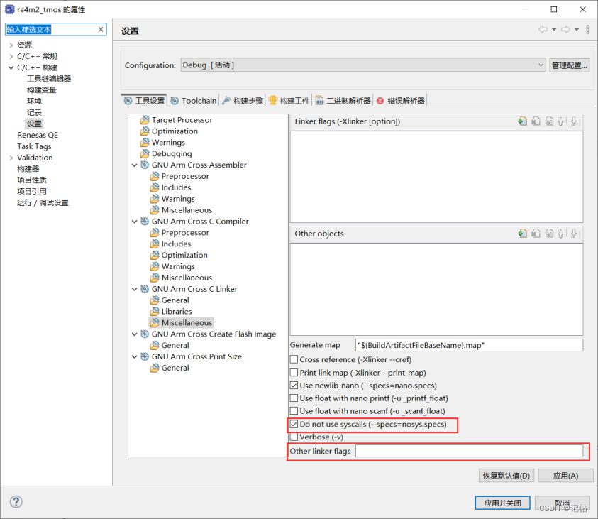
e2studio的重定向printf设置
在嵌入式系统的开发中,尤其是在使用GNU编译器集合(GCC)时,–specs 参数用于指定链接时使用的系统规格(specs)文件。这些规格文件控制了编译器和链接器的行为,尤其是关于系统库和启动代码的链接。–specs=rdimon.specs 和 --specs=nosys.specs 是两种常见的规格文件,它们用于不同的场景。
–specs=rdimon.specs
用途: 这个选项用于链接“Redlib”库,这是为裸机(bare-metal)和半主机(semihosting)环境设计的C库的一个变体。半主机环境是一种特殊的运行模式,允许嵌入式程序通过宿主机(如开发PC)的调试器进行输入输出操作。
应用场景: 当你需要在没有完整操作系统的环境中运行程序,但同时需要使用调试器来处理输入输出(例如打印到宿主机的终端),这个选项非常有用。
特点: 它提供了一些基本的系统调用,通过调试接口与宿主机通信。
–specs=nosys.specs
用途: 这个选项链接了一个非常基本的系统库,这个库不提供任何系统服务的实现。
应用场景: 适用于完全的裸机程序,其中程序不执行任何操作系统调用,比如不进行文件操作或者系统级输入输出。
特点: 这是一个更“裸”的环境,没有任何操作系统支持。使用这个规格文件,程序不期望有操作系统层面的任何支持。
如果你的程序需要与宿主机进行交互(如在开发期间的调试),并且通过调试器进行基本的输入输出操作,则使用 --specs=rdimon.specs。
如果你的程序是完全独立的,不需要任何形式的操作系统服务,包括不进行任何系统级的输入输出,则使用 --specs=nosys.specs。
R_SCI_UART_Open()函数原型
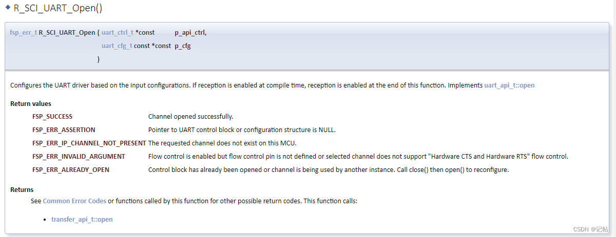
故可以用 R_SCI_UART_Open()函数进行配置,开启和初始化UART。
/* Open the transfer instance with initial configuration. */
    err = R_SCI_UART_Open(&g_uart9_ctrl, &g_uart9_cfg);
    assert(FSP_SUCCESS == err);
回调函数user_uart_callback ()
当数据发送的时候,可以查看UART_EVENT_TX_COMPLETE来判断是否发送完毕。
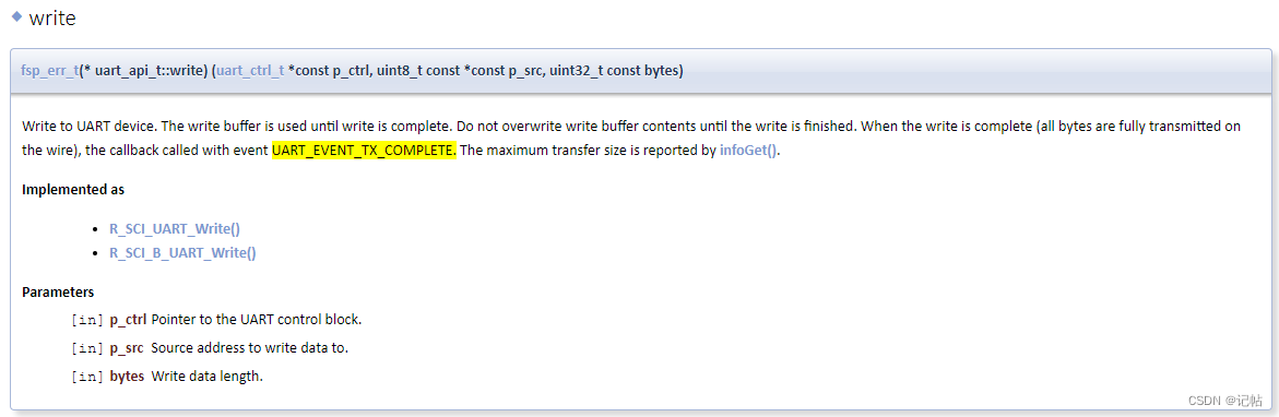
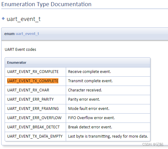
可以检查检查 "p_args" 结构体中的 "event" 字段的值是否等于 "UART_EVENT_TX_COMPLETE"。如果条件为真,那么 if 语句后面的代码块将会执行。
fsp_err_t err = FSP_SUCCESS;
volatile bool uart_send_complete_flag = false;
void user_uart_callback (uart_callback_args_t * p_args)
{
    if(p_args- >event == UART_EVENT_TX_COMPLETE)
    {
        uart_send_complete_flag = true;
    }
}
printf输出重定向到串口
打印最常用的方法是printf,所以要解决的问题是将printf的输出重定向到串口,然后通过串口将数据发送出去。 注意一定要加上头文件#include
#ifdef __GNUC__                                 //串口重定向
    #define PUTCHAR_PROTOTYPE int __io_putchar(int ch)
#else
    #define PUTCHAR_PROTOTYPE int fputc(int ch, FILE *f)
#endif

PUTCHAR_PROTOTYPE
{
        err = R_SCI_UART_Write(&g_uart9_ctrl, (uint8_t *)&ch, 1);
        if(FSP_SUCCESS != err) __BKPT();
        while(uart_send_complete_flag == false){}
        uart_send_complete_flag = false;
        return ch;
}

int _write(int fd,char *pBuffer,int size)
{
    for(int i=0;i< size;i++)
    {
        __io_putchar(*pBuffer++);
    }
    return size;
}
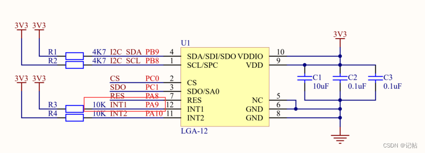
IIC属性配置
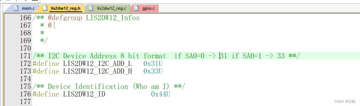
查看手册,可以得知LIS2DW12的IIC地址为“0011000” 或者 “0011001”,即0x18或0x19。

初始换管脚
由于需要向LIS2DW12_I2C_ADD_L写入以及为IIC模式。

所以使能CS为高电平,配置为IIC模式。

配置SA0为低电平。

R_IOPORT_PinWrite(&g_ioport_ctrl, BSP_IO_PORT_00_PIN_00, BSP_IO_LEVEL_HIGH);
    R_IOPORT_PinWrite(&g_ioport_ctrl, BSP_IO_PORT_00_PIN_01, BSP_IO_LEVEL_LOW);
IIC配置
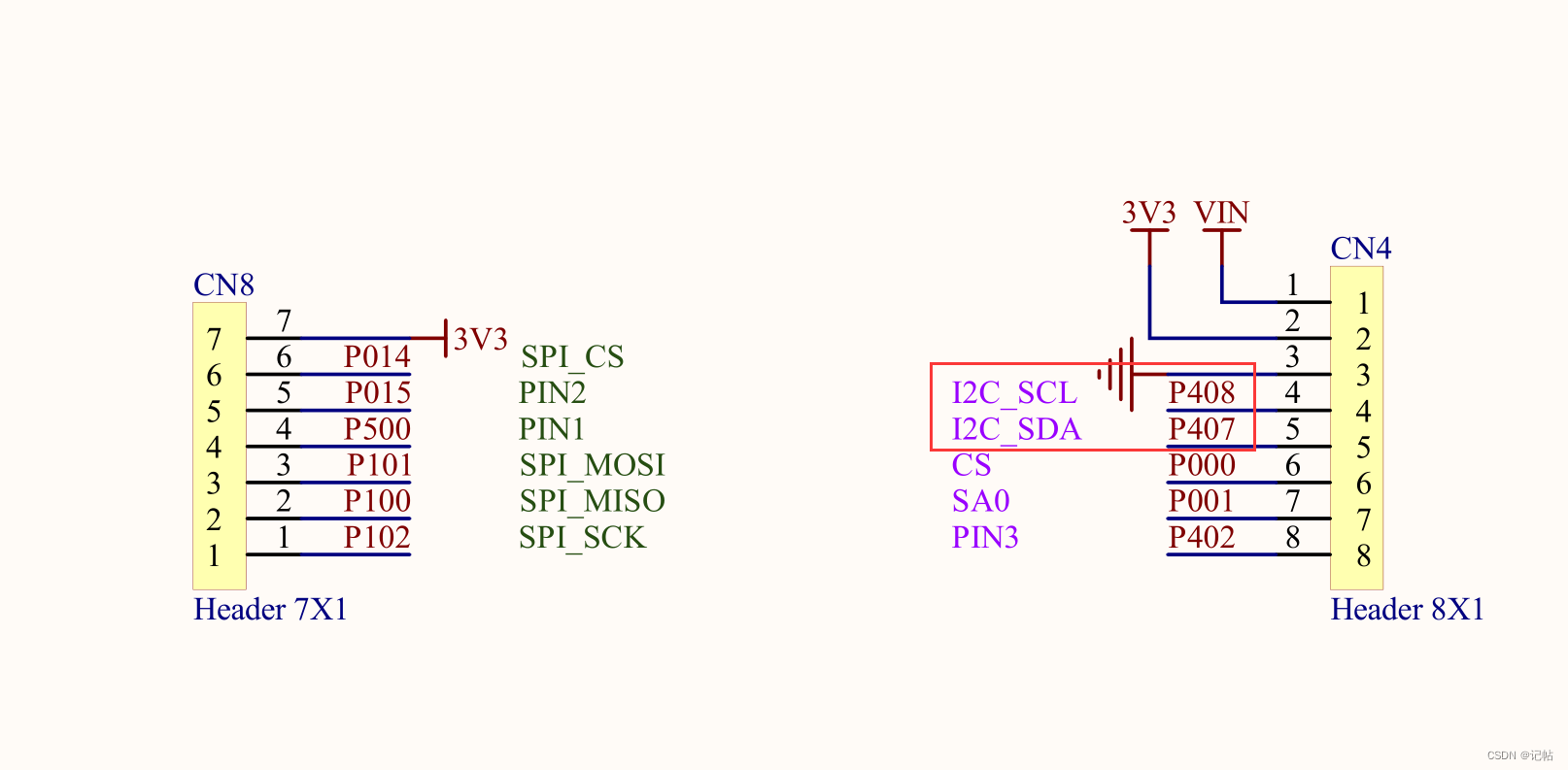
配置RA4M2的I2C接口,使其作为I2C master进行通信。 查看开发板原理图,对应的IIC为P407和P408。
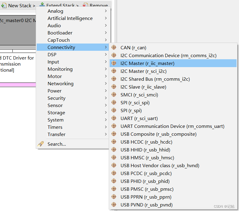
点击Stacks->New Stack->Connectivity -> I2C Master(r_iic_master)。
设置IIC的配置,需要注意从机的地址。

R_IIC_MASTER_Open()函数原型
R_IIC_MASTER_Open()函数为执行IIC初始化,开启配置如下所示。
/* Initialize the I2C module */
    err = R_IIC_MASTER_Open(&g_i2c_master0_ctrl, &g_i2c_master0_cfg);
    /* Handle any errors. This function should be defined by the user. */
    assert(FSP_SUCCESS == err);
R_IIC_MASTER_Write()函数原型
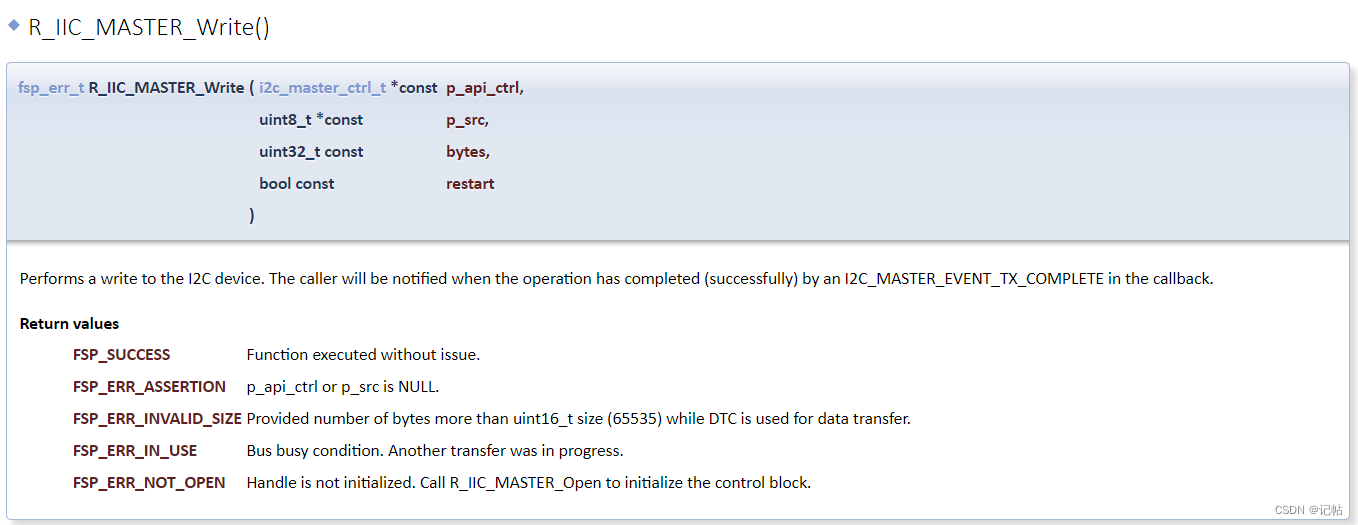
R_IIC_MASTER_Write()函数是向IIC设备中写入数据,写入格式如下所示。
err = R_IIC_MASTER_Write(&g_i2c_master0_ctrl, ®, 1, true);
assert(FSP_SUCCESS == err);
R_IIC_MASTER_Read()函数原型
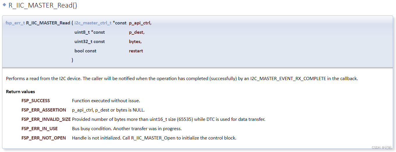
R_SCI_I2C_Read()函数是向IIC设备中读取数据,读取格式如下所示。
/* Read data from I2C slave */
    err = R_IIC_MASTER_Read(&g_i2c_master0_ctrl, bufp, len, false);
    assert(FSP_SUCCESS == err);
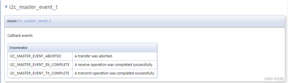
sci_i2c_master_callback()回调函数
对于数据是否发送完毕,可以查看是否获取到I2C_MASTER_EVENT_TX_COMPLETE字段。
/* Callback function */
i2c_master_event_t i2c_event = I2C_MASTER_EVENT_ABORTED;
uint32_t  timeout_ms = 100000;
void sci_i2c_master_callback(i2c_master_callback_args_t *p_args)
{
    i2c_event = I2C_MASTER_EVENT_ABORTED;
    if (NULL != p_args)
    {
        /* capture callback event for validating the i2c transfer event*/
        i2c_event = p_args- >event;
    }
}
INT1设置
数据准备完毕可以通过INT1获取中断信号。
INT1接入PA9,需要配置PA9为输入模式。

配置如下所示。

参考程序
[https://github.com/STMicroelectronics/lis2dw12-pid]
初始换管脚
由于需要向LIS2DW12_I2C_ADD_H写入以及为IIC模式。
所以使能CS为高电平,配置为IIC模式。 配置SA0为高电平。
R_IOPORT_PinWrite(&g_ioport_ctrl, BSP_IO_PORT_00_PIN_00, BSP_IO_LEVEL_HIGH);
        R_IOPORT_PinWrite(&g_ioport_ctrl, BSP_IO_PORT_00_PIN_01, BSP_IO_LEVEL_LOW);


        /* Initialize the I2C module */
        err = R_IIC_MASTER_Open(&g_i2c_master0_ctrl, &g_i2c_master0_cfg);
        /* Handle any errors. This function should be defined by the user. */
        assert(FSP_SUCCESS == err);

        /* Initialize mems driver interface */
        stmdev_ctx_t dev_ctx;
        dev_ctx.write_reg = platform_write;
        dev_ctx.read_reg = platform_read;
        dev_ctx.handle = &SENSOR_BUS;
        /* Wait sensor boot time */
        platform_delay(BOOT_TIME);
获取ID
我们可以向WHO_AM_I (0Fh)获取固定值,判断是否为0x44。
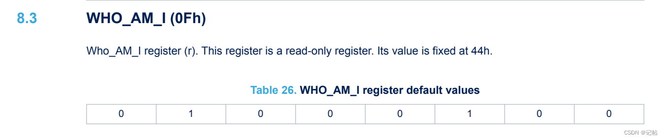
lis2dw12_device_id_get为获取函数。
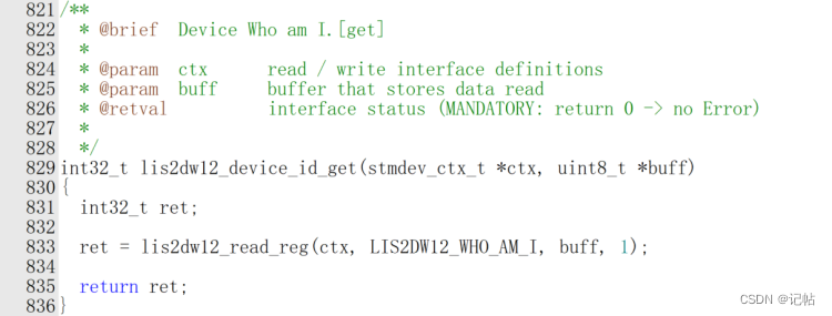
对应的获取ID驱动程序,如下所示。
/* Check device ID */
        lis2dw12_device_id_get(&dev_ctx, &whoamI);
        printf("LIS2DW12_ID=0x%x,whoamI=0x%xn",LIS2DW12_ID,whoamI);
        if (whoamI != LIS2DW12_ID)
            while (1) {
          /* manage here device not found */
            }
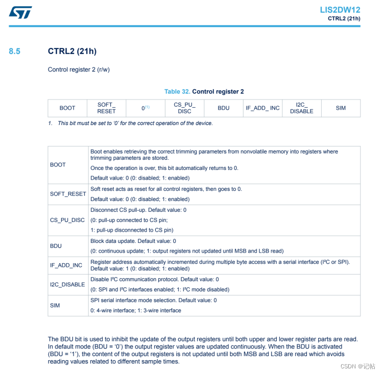
复位操作
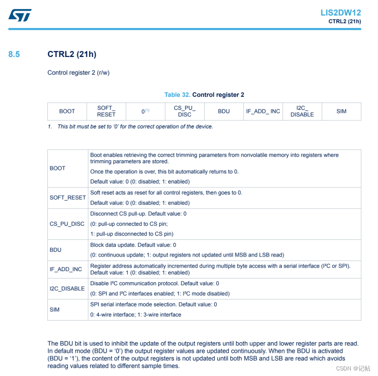
可以向CTRL2 (21h)的SOFT_RESET寄存器写入1进行复位。
lis2dw12_reset_set为重置函数。
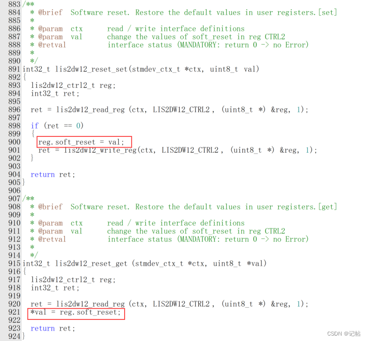
对应的驱动程序,如下所示。
/* Restore default configuration */
  lis2dw12_reset_set(&dev_ctx, PROPERTY_ENABLE);

  do {
    lis2dw12_reset_get(&dev_ctx, &rst);
  } while (rst);
BDU设置
在很多传感器中,数据通常被存储在输出寄存器中,这些寄存器分为两部分:MSB和LSB。这两部分共同表示一个完整的数据值。例如,在一个加速度计中,MSB和LSB可能共同表示一个加速度的测量值。
连续更新模式(BDU = ‘0’):在默认模式下,输出寄存器的值会持续不断地被更新。这意味着在你读取MSB和LSB的时候,寄存器中的数据可能会因为新的测量数据而更新。这可能导致一个问题:当你读取MSB时,如果寄存器更新了,接下来读取的LSB可能就是新的测量值的一部分,而不是与MSB相对应的值。这样,你得到的就是一个“拼凑”的数据,它可能无法准确代表任何实际的测量时刻。
块数据更新(BDU)模式(BDU = ‘1’):当激活BDU功能时,输出寄存器中的内容不会在读取MSB和LSB之间更新。这就意味着一旦开始读取数据(无论是先读MSB还是LSB),寄存器中的那一组数据就被“锁定”,直到两部分都被读取完毕。这样可以确保你读取的MSB和LSB是同一测量时刻的数据,避免了读取到代表不同采样时刻的数据。
简而言之,BDU位的作用是确保在读取数据时,输出寄存器的内容保持稳定,从而避免读取到拼凑或错误的数据。这对于需要高精度和稳定性的应用尤为重要。
可以向CTRL2 (21h)的BDU寄存器写入1进行开启。
对应的驱动程序,如下所示。
/* Enable Block Data Update */
  lis2dw12_block_data_update_set(&dev_ctx, PROPERTY_ENABLE);
开启INT1中断
设置中断通知方式。LIS2DW12_INT_LATCHED 表明使用锁存型中断,意味着中断信号会保持激活状态,直到被读取或者清除。
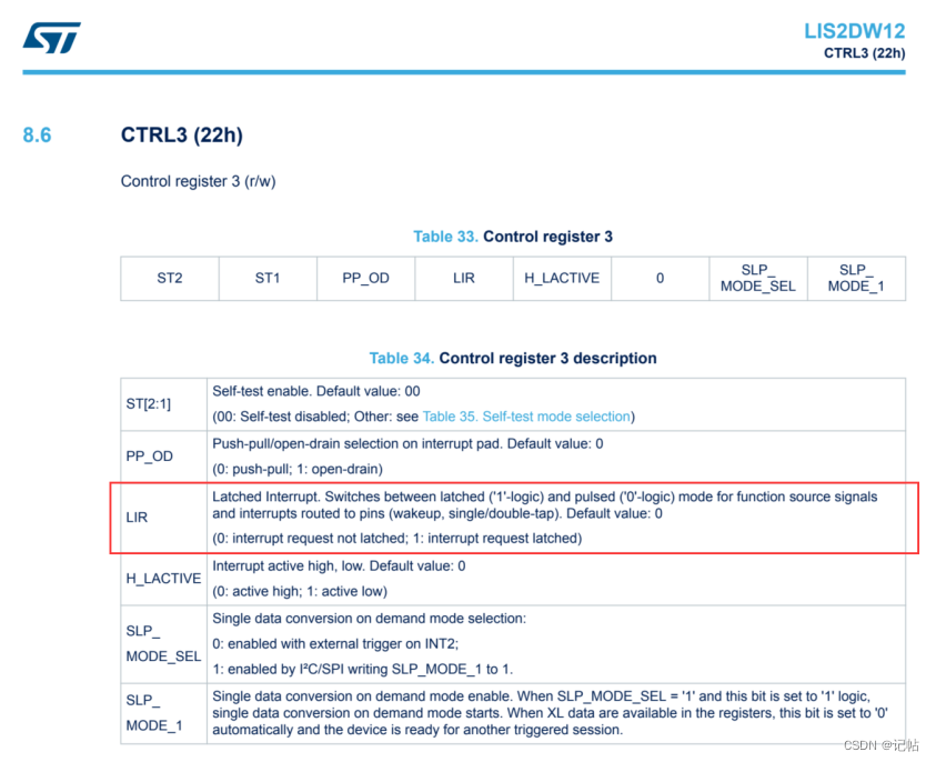
lis2dw12_int_notification_set(&dev_ctx, LIS2DW12_INT_LATCHED);
设置中断引脚的极性。LIS2DW12_ACTIVE_LOW 指示中断引脚在激活时是低电平。
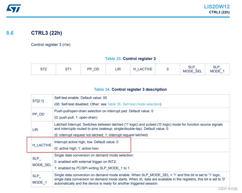
lis2dw12_pin_polarity_set(&dev_ctx, LIS2DW12_ACTIVE_LOW);
读取 INT1 引脚的当前中断路由配置到 ctrl4_int1_pad 结构体中,(CTRL4_INT1_PAD_CTRL, 地址为 0x23h)这个寄存器用于配置加速度计的中断1引脚(INT1)的行为。
INT1_6D: 当设置为1时,6D定位识别的中断会被路由到INT1引脚。
INT1_SINGLE_TAP: 单击识别中断的启用/禁用。
INT1_WU: 唤醒识别中断的启用/禁用。
INT1_FF: 自由落体识别中断的启用/禁用。
INT1_TAP: 双击识别中断的启用/禁用。
INT1_DIFF5: FIFO满识别中断的启用/禁用。
INT1_FTH: FIFO阈值中断的启用/禁用。
INT1_DRDY: 数据就绪(Data-Ready)中断的启用/禁用。
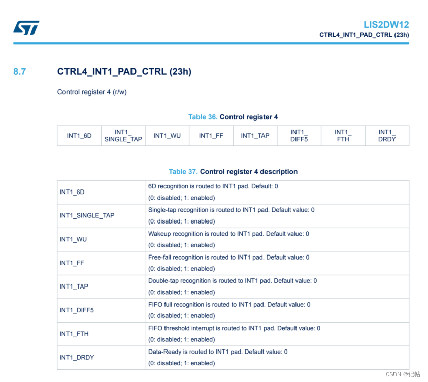
需要将INT1_DRDY置为1。 然后再将数据写入到(CTRL4_INT1_PAD_CTRL, 地址为 0x23h)这个寄存器钟。
lis2dw12_pin_int1_route_get(&dev_ctx, &ctrl4_int1_pad);
  ctrl4_int1_pad.int1_drdy = PROPERTY_ENABLE;
  lis2dw12_pin_int1_route_set(&dev_ctx, &ctrl4_int1_pad);
设置传感器的量程
FS[1:0] - 全量程选择:这两个位用于设置传感器的量程。量程决定了传感器可以测量的最大加速度值。例如,量程可以设置为±2g、±4g、±8g或±16g。这允许用户根据应用的特定需求调整传感器的灵敏度。
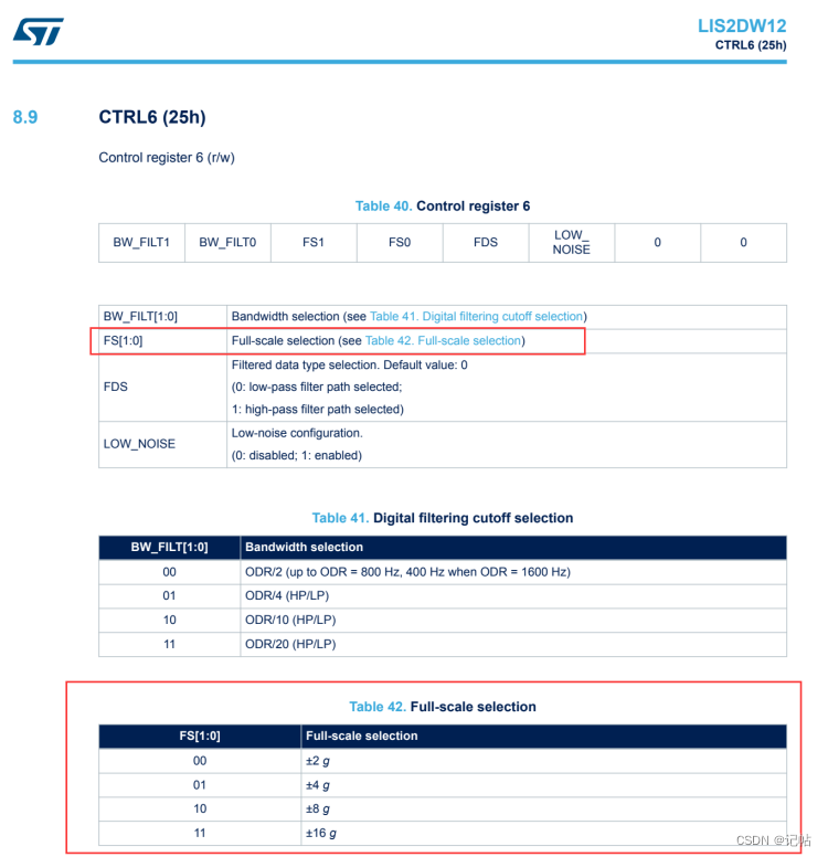
对应的驱动程序,如下所示。
/* Set full scale */
  lis2dw12_full_scale_set(&dev_ctx, LIS2DW12_2g);
配置过滤器链
lis2dw12_filter_path_set(&dev_ctx, LIS2DW12_LPF_ON_OUT);:设置加速度计输出的过滤器路径。这里选择了输出上的低通滤波器(LPF),用于去除高频噪声。
lis2dw12_filter_bandwidth_set(&dev_ctx, LIS2DW12_ODR_DIV_10);设置过滤器的带宽。LIS2DW12_ODR_DIV_10 表明带宽设置为输出数据率(ODR)的十分之一。
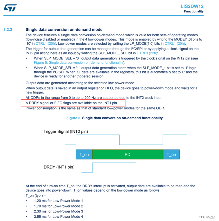
配置电源模式
lis2dw12_power_mode_set(&dev_ctx, LIS2DW12_CONT_LOW_PWR_12bit);配置电源模式。这里设置为连续低功耗模式,且以 12 位分辨率运行。
设置输出数据速率
lis2dw12_data_rate_set(&dev_ctx, LIS2DW12_XL_SET_SW_TRIG);设置加速度计的数据输出速率。LIS2DW12_XL_SET_SW_TRIG 可能表示使用软件触发来设置数据输出速率。
/* Wait sensor boot time */
  platform_delay(BOOT_TIME);
  /* Check device ID */
  lis2dw12_device_id_get(&dev_ctx, &whoamI);

  if (whoamI != LIS2DW12_ID)
    while (1) {
      /* manage here device not found */
    }

  /* Restore default configuration */
  lis2dw12_reset_set(&dev_ctx, PROPERTY_ENABLE);

  do {
    lis2dw12_reset_get(&dev_ctx, &rst);
  } while (rst);

  /* Enable Block Data Update */
  lis2dw12_block_data_update_set(&dev_ctx, PROPERTY_ENABLE);

  lis2dw12_int_notification_set(&dev_ctx, LIS2DW12_INT_LATCHED);
  lis2dw12_pin_polarity_set(&dev_ctx, LIS2DW12_ACTIVE_LOW);
  lis2dw12_pin_int1_route_get(&dev_ctx, &ctrl4_int1_pad);
  ctrl4_int1_pad.int1_drdy = PROPERTY_ENABLE;
  lis2dw12_pin_int1_route_set(&dev_ctx, &ctrl4_int1_pad);
  /* Set full scale */
  lis2dw12_full_scale_set(&dev_ctx, LIS2DW12_2g);
  /* Configure filtering chain accelerometer */
  lis2dw12_filter_path_set(&dev_ctx, LIS2DW12_LPF_ON_OUT);
  lis2dw12_filter_bandwidth_set(&dev_ctx, LIS2DW12_ODR_DIV_10);
  /* Configure power mode and Output Data Rate */
  lis2dw12_power_mode_set(&dev_ctx, LIS2DW12_CONT_LOW_PWR_12bit);
  lis2dw12_data_rate_set(&dev_ctx, LIS2DW12_XL_SET_SW_TRIG);
中断判断加速度数据状态
通过判断INT1管脚来判断数据是否准备完毕。 如果电平为低电平说明加速度数据已经准备完毕。
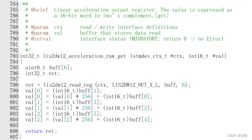
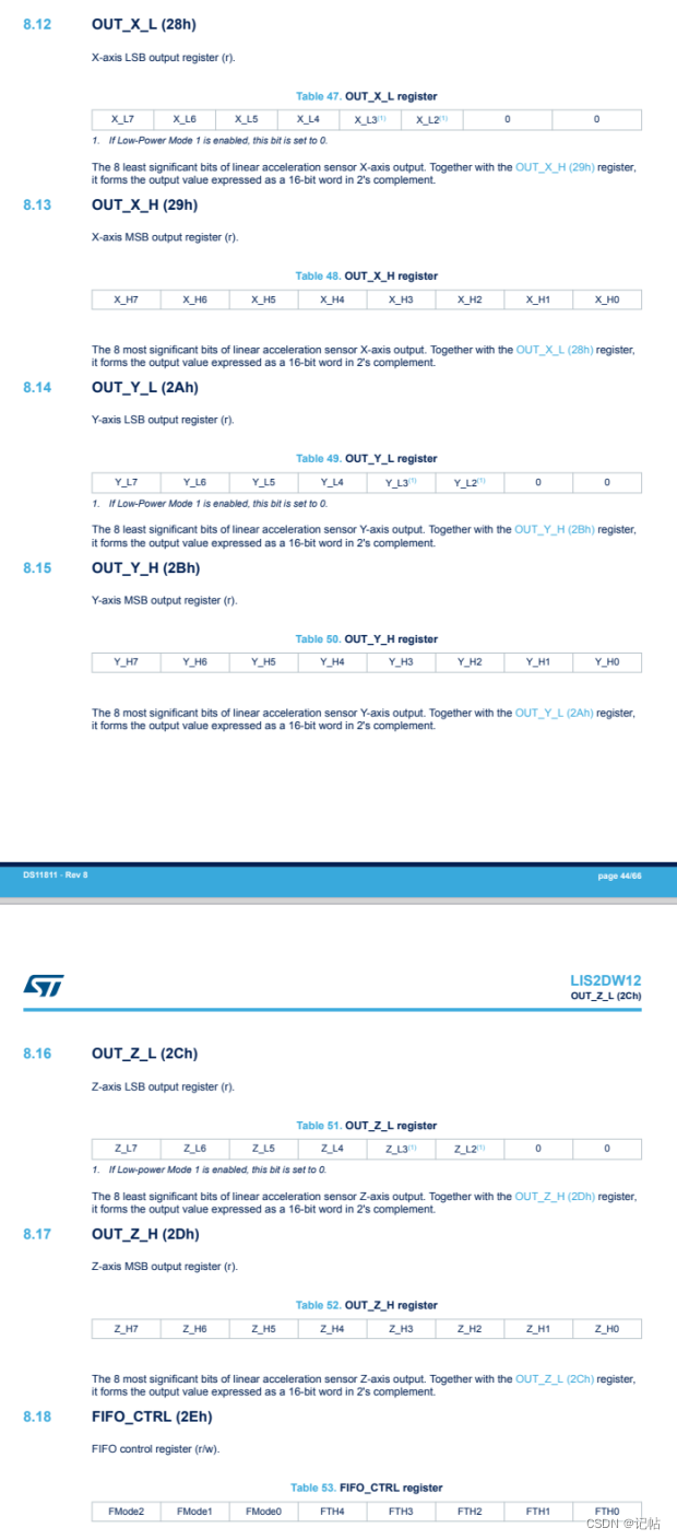
数据在28h-2Dh中。
加速度数据首先以原始格式(通常是整数)读取,然后需要转换为更有意义的单位,如毫重力(mg)。这里的转换函数 lis2dw12_from_fs2_to_mg() 根据加速度计的量程(这里假设为±2g)将原始数据转换为毫重力单位。 acceleration_mg[0] = lis2dw12_from_fs2_to_mg(data_raw_acceleration[0]); 等三行代码分别转换 X、Y、Z 轴的加速度数据。
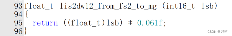
● LIS2DW12 加速度计通常会有一个固定的位分辨率,比如 16 位(即输出值是一个 16 位的整数)。这意味着加速度计可以输出的不同值的总数是 2^16=65536。这些值均匀地分布在 -2g 到 +2g 的范围内。
● 因此,这个范围(4g 或者 4000 mg)被分成了 65536 个步长。
● 每个步长的大小是 4000 mg/65536≈0.061 mg/LSB
所以,函数中的乘法 ((float_t)lsb) * 0.061f 是将原始的整数值转换为以毫重力(mg)为单位的加速度值。这个转换对于将加速度计的原始读数转换为实际的物理测量值是必需的。
while(1)
{
bsp_io_level_t p_port_value_port_015;
R_IOPORT_PinRead(&g_ioport_ctrl, BSP_IO_PORT_00_PIN_15, &p_port_value_port_015);
if(p_port_value_port_015==0)
{
/* Read acceleration data */
memset(data_raw_acceleration, 0x00, 3 * sizeof(int16_t));
lis2dw12_acceleration_raw_get(&dev_ctx, data_raw_acceleration);
acceleration_mg[0] = lis2dw12_from_fs2_lp1_to_mg(
data_raw_acceleration[0]);
acceleration_mg[1] = lis2dw12_from_fs2_lp1_to_mg(
data_raw_acceleration[1]);
acceleration_mg[2] = lis2dw12_from_fs2_lp1_to_mg(
data_raw_acceleration[2]);
lis2dw12_data_rate_set(&dev_ctx, LIS2DW12_XL_SET_SW_TRIG);
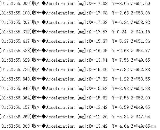
printf("Acceleration [mg]:X=%4.2ftY=%4.2ftZ=%4.2frn",acceleration_mg[0], acceleration_mg[1], acceleration_mg[2]);
}
}
主程序
#include "hal_data.h"


#include < stdio.h >

#include "lis2dw12_reg.h"


fsp_err_t err = FSP_SUCCESS;
volatile bool uart_send_complete_flag = false;
void user_uart_callback (uart_callback_args_t * p_args)
{
    if(p_args- >event == UART_EVENT_TX_COMPLETE)
    {
        uart_send_complete_flag = true;
    }
}


/* Callback function */
i2c_master_event_t i2c_event = I2C_MASTER_EVENT_ABORTED;
uint32_t  timeout_ms = 100000;
void sci_i2c_master_callback(i2c_master_callback_args_t *p_args)
{
    i2c_event = I2C_MASTER_EVENT_ABORTED;
    if (NULL != p_args)
    {
        /* capture callback event for validating the i2c transfer event*/
        i2c_event = p_args- >event;
    }
}


#ifdef __GNUC__                                 //串口重定向
    #define PUTCHAR_PROTOTYPE int __io_putchar(int ch)
#else
    #define PUTCHAR_PROTOTYPE int fputc(int ch, FILE *f)
#endif

PUTCHAR_PROTOTYPE
{
        err = R_SCI_UART_Write(&g_uart9_ctrl, (uint8_t *)&ch, 1);
        if(FSP_SUCCESS != err) __BKPT();
        while(uart_send_complete_flag == false){}
        uart_send_complete_flag = false;
        return ch;
}

int _write(int fd,char *pBuffer,int size)
{
    for(int i=0;i< size;i++)
    {
        __io_putchar(*pBuffer++);
    }
    return size;
}


FSP_CPP_HEADER
void R_BSP_WarmStart(bsp_warm_start_event_t event);
FSP_CPP_FOOTER


#define SENSOR_BUS g_i2c_master0_ctrl
/* Private macro -------------------------------------------------------------*/
#define    BOOT_TIME            20 //ms

/* Private variables ---------------------------------------------------------*/
static int16_t data_raw_acceleration[3];
static float acceleration_mg[3];
static uint8_t whoamI, rst;
static uint8_t tx_buffer[1000];

/* Extern variables ----------------------------------------------------------*/

/* Private functions ---------------------------------------------------------*/
/*
 *   WARNING:
 *   Functions declare in this section are defined at the end of this file
 *   and are strictly related to the hardware platform used.
 *
 */
static int32_t platform_write(void *handle, uint8_t reg, const uint8_t *bufp,
                              uint16_t len);
static int32_t platform_read(void *handle, uint8_t reg, uint8_t *bufp,
                             uint16_t len);
static void tx_com( uint8_t *tx_buffer, uint16_t len );
static void platform_delay(uint32_t ms);
static void platform_init(void);

static int16_t data_raw_acceleration[3];
static float acceleration_mg[3];
static lis2dw12_ctrl4_int1_pad_ctrl_t  ctrl4_int1_pad;
/*******************************************************************************************************************//**
 * main() is generated by the RA Configuration editor and is used to generate threads if an RTOS is used.  This function
 * is called by main() when no RTOS is used.
 **********************************************************************************************************************/
void hal_entry(void)
{
    /* TODO: add your own code here */

    /* Open the transfer instance with initial configuration. */
        err = R_SCI_UART_Open(&g_uart9_ctrl, &g_uart9_cfg);
        assert(FSP_SUCCESS == err);

        printf("hello world!n");


        R_IOPORT_PinWrite(&g_ioport_ctrl, BSP_IO_PORT_00_PIN_00, BSP_IO_LEVEL_HIGH);
        R_IOPORT_PinWrite(&g_ioport_ctrl, BSP_IO_PORT_00_PIN_01, BSP_IO_LEVEL_LOW);


        /* Initialize the I2C module */
        err = R_IIC_MASTER_Open(&g_i2c_master0_ctrl, &g_i2c_master0_cfg);
        /* Handle any errors. This function should be defined by the user. */
        assert(FSP_SUCCESS == err);

        /* Initialize mems driver interface */
        stmdev_ctx_t dev_ctx;
        dev_ctx.write_reg = platform_write;
        dev_ctx.read_reg = platform_read;
        dev_ctx.handle = &SENSOR_BUS;
        /* Wait sensor boot time */
        platform_delay(BOOT_TIME);
        /* Check device ID */
        lis2dw12_device_id_get(&dev_ctx, &whoamI);
        printf("LIS2DW12_ID=0x%x,whoamI=0x%xn",LIS2DW12_ID,whoamI);
        if (whoamI != LIS2DW12_ID)
            while (1) {
          /* manage here device not found */
            }

        /* Restore default configuration */
        lis2dw12_reset_set(&dev_ctx, PROPERTY_ENABLE);

        do {
          lis2dw12_reset_get(&dev_ctx, &rst);
        } while (rst);

        /* Enable Block Data Update */
        lis2dw12_block_data_update_set(&dev_ctx, PROPERTY_ENABLE);

        lis2dw12_int_notification_set(&dev_ctx, LIS2DW12_INT_LATCHED);
        lis2dw12_pin_polarity_set(&dev_ctx, LIS2DW12_ACTIVE_LOW);
        lis2dw12_pin_int1_route_get(&dev_ctx, &ctrl4_int1_pad);
        ctrl4_int1_pad.int1_drdy = PROPERTY_ENABLE;
        lis2dw12_pin_int1_route_set(&dev_ctx, &ctrl4_int1_pad);
       /* Set full scale */
        lis2dw12_full_scale_set(&dev_ctx, LIS2DW12_2g);
        /* Configure filtering chain accelerometer */
        lis2dw12_filter_path_set(&dev_ctx, LIS2DW12_LPF_ON_OUT);
        lis2dw12_filter_bandwidth_set(&dev_ctx, LIS2DW12_ODR_DIV_10);
        /* Configure power mode and Output Data Rate */
        lis2dw12_power_mode_set(&dev_ctx, LIS2DW12_CONT_LOW_PWR_12bit);
        lis2dw12_data_rate_set(&dev_ctx, LIS2DW12_XL_SET_SW_TRIG);


        while(1)
        {
            bsp_io_level_t p_port_value_port_015;
            R_IOPORT_PinRead(&g_ioport_ctrl, BSP_IO_PORT_00_PIN_15, &p_port_value_port_015);
            if(p_port_value_port_015==0)
            {
                /* Read acceleration data */
                memset(data_raw_acceleration, 0x00, 3 * sizeof(int16_t));
                lis2dw12_acceleration_raw_get(&dev_ctx, data_raw_acceleration);
                acceleration_mg[0] = lis2dw12_from_fs2_lp1_to_mg(
                                       data_raw_acceleration[0]);
                acceleration_mg[1] = lis2dw12_from_fs2_lp1_to_mg(
                                       data_raw_acceleration[1]);
                acceleration_mg[2] = lis2dw12_from_fs2_lp1_to_mg(
                                       data_raw_acceleration[2]);

                lis2dw12_data_rate_set(&dev_ctx, LIS2DW12_XL_SET_SW_TRIG);
                      printf("Acceleration [mg]:X=%4.2ftY=%4.2ftZ=%4.2frn",acceleration_mg[0], acceleration_mg[1], acceleration_mg[2]);
            }
        }


#if BSP_TZ_SECURE_BUILD
    /* Enter non-secure code */
    R_BSP_NonSecureEnter();
#endif
}
演示
INT端口电平逻辑如下所示。

审核编辑 黄宇
-
三轴加速度计LIS2DW12开发(1)----轮询获取加速度数据2026-07-02 106
-
加速度计LIS2DW12开发(1)----轮询获取加速度数据2026-06-02 1736
-
e2studio开发三轴加速度计LIS2DW12(2)----基于中断信号获取加速度数据2024-08-09 1903
-
e2studio开发三轴加速度计LIS2DW12(4)----测量倾斜度2024-05-17 3059
-
三轴加速度计LIS2DW12开发(4)----测量倾斜度2024-05-16 3972
-
e2studio开发三轴加速度计LIS2DW12(1)----轮询获取加速度数据2024-01-09 2402
-
三轴加速度计LIS2DW12开发(2)----基于中断信号获取加速度数据2023-12-18 3426
全部0条评论

快来发表一下你的评论吧 !
