


萌版蜘蛛侠:爬墙机器人DIY作品秀
电子制作
描述
想挣脱地心引力的束缚?想练习跑酷在垂直的墙壁上疾走?——不要用崇拜的目光注视我,虽然我就是飞檐走壁,仁者无敌的可爱玲珑Wallbots!当然我也不介意你称呼我的艺名:【蜘蛛侠】
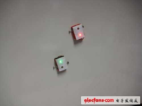
墙面上爬来爬去的是神马?!莫要惊慌,既不是壁虎也不是变异蜘蛛,它们是可爱的Wallbots——能在垂直表面进行穿越的机器人。想知道怎么制作?嗯哼,往下看吧~小W可以在任何含金属墙面上移动,包括电梯,白板,冰箱、金属门。 小W还配备了几个光传感器,通过它们可以进行简单的交互。 3种模式可供选择,通过光传感器进行转换: 红色走得快,趋近障碍物(例如人的手或者小W的兄弟姐妹们); 绿色走得慢,远离障碍; 黄色走得最慢,检测到物体时完全停止。
1 工具和材料
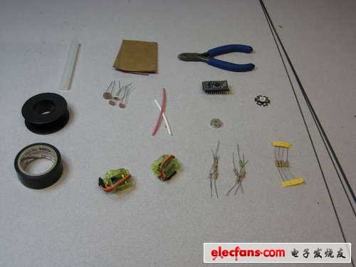
● 一些不易弯曲的硬线
● 绝缘胶布
● 线
● 硬板纸
● 胶棒
● 热胶q1an9
● 剪刀
● 剪钳(绞线的那个)
●2.2K欧姆电阻*4
● 10K欧姆电阻
● 100欧姆电阻
● Arduino Mini(单片机)
● 伺服电机*2
● 磁铁片*6
● 1个RGB LED灯
● 1个轻型的电池
2. 使伺服电机连续运转之入门篇

● 把固定它的壳子打开,对每个伺服机做简单修改就能得到我们需要的连续转动,先撬开壳子。

● 把妨碍转动的壳子剪掉,这样电位计就能一直获得连续信号。
● 这个黑色的部分是用来让它转了180度后停止的,看见没?两个黑色塑料小片儿。

● 取下齿轮
● 把黑色壳子上的线剪下(下一个大步会告诉你怎么处理它们)。

● 把挡着连续转动的小塑料片儿剪掉。
3 使伺服电机连续转动之进阶篇
● 现在,电位计已被成功调戏~(≧▽≦)/~,她一直采集连续信号。
● 从黑壳子上剪出红色,绿色和黄色的线(这个应当在上一步就做好了)。

● 绿色的线和黄色线之间焊个2.2K的电阻
● 在红色和黄色的线之间也焊个2.2K的电阻
4 反向设置

● 在相同模拟信号下,伺服机的转向一般是相同的。他们对称安装在小W上,但是要让一个反向怎么办?在硬件和软件上都可以解决(我用硬件做的,因为我是代码懒人,摔!)。
● 剪下电机到电机板子上的红色和蓝色的线。
● 焊接红线到蓝线,然后蓝线到红线(头晕了吧?其实就是像图上那样交叉一下)。
5 组装电机

● 这步很容易嘿!尽可能温柔滴把线塞到伺服机壳子里面,然后把齿轮装配好。可是捏,我加了电阻后,以前的壳子就不合适了,所以我用绝缘胶布把他们缠在一块儿的。
6 齿轮上阵

● 怎么附上去呢?我用的热胶,其实任何粘性强的玩意儿都可以使,先剪两根1英寸长的硬线。

● 把每根线用热胶粘在伺服机顶部的齿轮里面。线要对半,露一半出来!

● 在每根线的末端粘3个磁盘。磁盘也必须是对准中心!
7 伺服机与单片机对接

● 我用PIN 9和 PIN 10来驱动电机。
● Pin 9 -》伺服机1的橙线。
● Pin 10 -》伺服机2的橙线
● Ground -》伺服机1,2的黑线。
● VCC -》伺服机1,2的红线。
8 接光敏电阻

● 把每个光敏电阻(光传感器)都连到Arduino上,一共4个传感器,左、右、前、后。

● 每个光传感器的电路图下面有,传感器的一条线连接到VCC;另一条线连到10K和100欧姆的电阻上。10K电阻接地,100欧姆电阻连接输入端。每个传感器的输入(绿线)连到MINI上的模拟端口(A0,A1,A2,A3)。

● 我程序里是这样设置的:Analog 0 -》 顶部的传感器;Analog 1 -》 左边的传感器;Analog 2 -》 前面的传感器;Analog 3 -》 右边的传感器。
9 加上RGB LED灯

● 把每个光敏电阻(光传感器)都连到Arduino上,一共4个传感器,左、右、前、后。
● 你是不是想在每个端口和LED灯之间放个电阻(200 欧姆左右)?我没有酱紫,因为我的LED灯可以承受的电压比Arduino能提供的高得多,所以不会被烧。
10 安装电池● 其实捏,能提供3—4V的电池都可以用,越轻越好。我使用了sparkfun锂电池。接地,然后高压直接接Arduino的VCC口。
11 上程序!● 这代码是关于2个伺服电机根据4个光传感器的输入值而进行驱动。根据模式,有几种运动方式。
*/
#include 《Servo.h》
// Right and left servos
Servo servo1;
Servo servo2;
// Light Sensors
int topSensor = 0; //700
int leftSensor = 1; /// Threshhold is 400
int frontSensor = 2; //400
int rightSensor = 3; //300
// Hardcoded thresholds (not used because we auto-calibrate)
int topThreshhold = 400;
int leftThreshhold = 550;
int frontThreshhold = 200;
int rightThreshhold = 650;
// Current robot type (red gree or yellow)
int STATE = 0;
// State values
int RED = 0;
int GREEN = 1;
int ORANGE = 2;
// Pins to drive the top tri-color LED
int redPin = 5;
int greenPin = 6;
// Values to hold sensor readings
int front;
int right;
int left;
int top;
// Auto-calibrate light sensor thresholds
void calibrate() {
Serial.println(“CALIBRATING”);
long int val = 0;
for (int i = 0; i《5; i++) {
val += analogRead(frontSensor);
delay(10);
}
frontThreshhold = (val /5) - 80;
val = 0;
for (int i = 0; i《5; i++) {
val = val + analogRead(topSensor);
Serial.println(analogRead(topSensor));
Serial.println(val);
delay(10);
}
topThreshhold = (val /5) -200;
val = 0;
for (int i = 0; i《5; i++) {
val += analogRead(rightSensor);
}
rightThreshhold = (val /5) - 100;
val = 0;
for (int i = 0; i《5; i++) {
val += analogRead(leftSensor);
}
leftThreshhold = (val /5) - 100;
// Print threshold values for debug
Serial.print(“top: ”);
Serial.println(topThreshhold);
Serial.print(“right: ”);
Serial.println(rightThreshhold);
Serial.print(“left: ”);
Serial.println(leftThreshhold);
Serial.print(“front: ”);
Serial.println(frontThreshhold);
}
void setup()
{
// turn on pin 13 for debug
pinMode(13, OUTPUT);
digitalWrite(13, HIGH);
// setup sensor pins
for (int i = 0; i《4; i++) {
pinMode(i, INPUT);
}
Serial.begin(9600);
calibrate();
// generate a random state
STATE = random(0, 3);
setColor(STATE);
}
// MOTOR FUNCTIONS
void turnLeft()
{
Serial.println(“LEFT”);
start();
delay(20);
for (int i = 0; i《20; i++) {
servo2.write(179);
servo1.write(1);
delay(20);
}
stop();
delay(20);
}
void turnRight() {
Serial.println(“RIGHT”);
start();
delay(20);
for (int i = 0; i《20; i++) {
servo2.write(1);
servo1.write(179);
delay(20);
}
stop();
delay(20);
}
void goForward(int del = 20) {
Serial.println(“FORWARD”);
start();
delay(20);
for (int i = 0; i《20; i++) {
servo1.write(179);
servo2.write(179);
delay(del);
}
stop();
delay(20);
}
void stop() {
servo1.detach();
servo2.detach();
delay(10);
}
void start() {
servo1.attach(10);
servo2.attach(9);
}
// Set the color of the top tri-color LED based on the current state
void setColor(int color) {
if (color == RED) {
digitalWrite(greenPin, 0);
analogWrite(redPin, 180);
}
else if (color == GREEN) {
digitalWrite(redPin, 0);
analogWrite(greenPin, 180);
}
else if (color == ORANGE) {
analogWrite(redPin, 100);
analogWrite(greenPin, 100);
}
}
// Blink the yellow color (when robot is confused)
void blinkOrange() {
for (int i = 0; i《5; i++) {
analogWrite(redPin, 100);
analogWrite(greenPin, 100);
delay(300);
digitalWrite(redPin, 0);
digitalWrite(greenPin, 0);
delay(300);
}
analogWrite(redPin, 100);
analogWrite(greenPin, 100);
}
void loop()
{
top = analogRead(topSensor);
long int time = millis();
while (analogRead(topSensor) 《 topThreshhold) {
delay(10); // while there is an arm wave from the user don‘t do anything
}
if ((millis() - time) 》 3000) {
// if the sensor was covered for more than 3 seconds, re-calibrate
calibrate();
}
// if the top sensor was covered, we change state
if (top 《 topThreshhold) {
STATE = (STATE+1) %3;
setColor(STATE);
Serial.print(“CHANGED STATE: ”);
Serial.println(STATE);
}
// Read the other sensors
right = analogRead(rightSensor);
left = analogRead(leftSensor);
front = analogRead(frontSensor);
if (STATE == RED) {
// go towards objects
if (front 《 frontThreshhold) {
goForward();
} else if (right 《 rightThreshhold) {
turnRight();
} else if (left《leftThreshhold) {
turnLeft();
} else {
goForward();
}
}
if (STATE == GREEN) {
// go away from objects
if (front 《 frontThreshhold) {
int dir = random(0,2);
if (dir == 0 && right 》 rightThreshhold) {
turnRight();
} else if (dir == 1 && left 》 leftThreshhold) {
turnLeft();
}
} else if (right 《 rightThreshhold) {
if (left 》 leftThreshhold) {
turnLeft();
} else {
goForward();
}
} else if (left《leftThreshhold) {
if (right 》 rightThreshhold) {
turnRight();
} else {
goForward();
}
} else {
goForward();
}
delay(200);
}
if (STATE == ORANGE) {
// only move if there are no hand motions- otherwise blink
int dir = random(0, 3);
if (left《leftThreshhold || right《rightThreshhold ||
front《leftThreshhold) {
blinkOrange();
} else {
if (dir == 0) {
goForward();
} else if (dir == 1) {
turnRight();
} else if (dir == 2) {
turnLeft();
}
delay(1000);
}
delay(10);
}
}
红色最快,趋向物体(当光传感器检测到光被挡住时);
蓝色是中速,背向物体(背向黑色区域);
黄色最慢,检测到物体就停止。
● 小W和它的兄弟姐妹们通过磁铁轮子在墙上运动,可以左转右转和前行;根据不同模式可进行调速。
● 当顶部的传感器被遮住超过3秒,所有传感器自动校准。
12 别让小W裸奔

● 给小W穿件衣裳。但之前必须确定程序能跑,然后你能分得清哪个伺服机是左,哪个是右。

● 因为小W要垂直运动,衣裳越轻越好啊!我用的硬纸壳,其实报纸或者轻塑料都能使。

● 我把伺服机用热胶黏在硬纸盒里,传感器分布在前后左右,然后用硬纸壳加固。为了让热传感器和齿轮舒舒服服在里面呆着,我量体裁衣剪了些洞。小W的顶部其实就是。。。就是一张纸!
● 然后。。。然后没有然后了,你就做好了,玩儿去吧!
-
 MinyonLew
2016-11-30
0 回复 举报请问单片机可以在那买到,求链接 收起回复
MinyonLew
2016-11-30
0 回复 举报请问单片机可以在那买到,求链接 收起回复
-
 蓝颜小帅
2012-09-28
0 回复 举报太给力了~ 收起回复
蓝颜小帅
2012-09-28
0 回复 举报太给力了~ 收起回复
-
DIY设计四足蜘蛛机器人2022-08-09 2109
-
联手 《蜘蛛侠:英雄远征》,realme推出联名潮机英雄礼盒2019-06-28 547
-
索尼影业与8th Wall推出蜘蛛侠Web AR体验,只要扫描二维码就能体验2019-03-27 1600
-
索尼影业为《蜘蛛侠:平行宇宙》推出Web AR体验2018-11-29 4593
-
2017机器人创想秀正式开赛2017-06-05 3008
-
电子元器件DIY可以爬墙的简单机器人2016-09-08 1579
-
★★★DIY6足仿生蜘蛛机器人 51单片机 WIFI控制★★★2016-04-15 13054
-
【秀作品海报制作】奖品收到了-艺术范儿的卡酷机器人2016-01-11 5750
-
超凡蜘蛛侠下面的是面板板?2015-07-08 2987
-
关于爬墙机器人2015-03-26 3278
-
《超凡蜘蛛侠2》里的电工原理2014-05-21 11729
-
蜘蛛侠的十二大科技武器2012-07-03 120059
-
萌版蜘蛛侠:爬墙机器人DIY作品秀2012-03-20 41418
-
【DIY作品秀】用iPhone制作智能机器人2012-01-10 15958
全部0条评论

快来发表一下你的评论吧 !
