

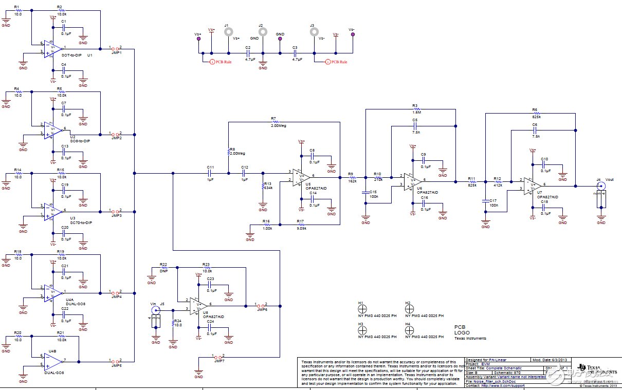
0.1-10Hz放大器噪声测量滤波器电路图
滤波器电路
96人已加入
描述
This circuit is designed to amplify low frequency noise (0.1Hz to 10Hz) to a level that is easily measured by and oscilloscope. It achieves this function with a 0.1Hz second order high pass filter and a to 10Hz forth order low pass filter. The 0.1Hz to 10Hz noise measurement is a common figure of merit given in amplifier data sheets. This design is intended to facilitate the measurement 0.1Hz to 10Hz noise for the commonly used different package styles.
声明:本文内容及配图由入驻作者撰写或者入驻合作网站授权转载。文章观点仅代表作者本人,不代表电子发烧友网立场。文章及其配图仅供工程师学习之用,如有内容侵权或者其他违规问题,请联系本站处理。
举报投诉
- 相关推荐
- 热点推荐
- 滤波器
-
低噪声放大器前端模块,带有 GPS/GNSS 预滤波器 skyworksinc2025-06-09 130
-
GNSS 低噪声放大器前端模块,集成前滤波器和后滤波器 skyworksinc2025-06-06 168
-
60Hz陷波滤波器电路图2023-07-27 4147
-
基于运算放大器的低音炮滤波器的电路图2023-04-02 8283
-
简述激励放大器与 ADC 之间的噪声规格关系2018-11-29 2947
-
如何选择噪声测量放大器2018-10-29 2852
-
怎么构建具有纳伏级灵敏度的低噪声仪表放大器2018-10-17 2077
-
基于0.1Hz 二阶高通滤波器对 0.1Hz- 10Hz 噪声进行滤波的参考设计包括原理图和BOM2018-08-02 5644
-
滤波器对白噪声的滤波效果2018-01-24 3706
-
0.1-10hz放大器噪声测量滤波器2017-05-11 2120
-
327Hz高通滤波器电路图2009-04-20 1973
-
0.1Hz-10Hz带通滤波器电路图2009-03-30 3775
全部0条评论

快来发表一下你的评论吧 !
