资料下载

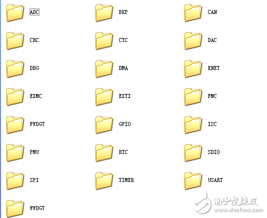
GD32F30x系列固件库
/*!
\file readme.txt
\brief description of the ADC0_ADC1_regular_parallel example
*/
/*
Copyright (C) 2017 GigaDevice
2017-02-10, V1.0.0, firmware for GD32F30x
*/
This demo is based on the GD32F30x-EVAL board, it shows how to
use ADC0 and ADC1 regular_parallel convert function. PA3 and PA0 are
configured in AIN mode. TIMER1_CH1 is the trigger source of ADC0. ADC1
external trigger chooses none. When the rising edge of TIMER1_CH1 coming,
ADC0 and ADC1 regular channels are triggered at the same time. The values
of ADC0 and ADC1 are transmit to array adc_value[] by DMA.
We can watch array adc_value[] in debug mode.
The ADC1 clock should below 42MHz.

声明:本文内容及配图由入驻作者撰写或者入驻合作网站授权转载。文章观点仅代表作者本人,不代表电子发烧友网立场。文章及其配图仅供工程师学习之用,如有内容侵权或者其他违规问题,请联系本站处理。 举报投诉
-
 addmark
2022-06-14
0 回复 举报感谢分享 收起回复
-
 zeshou
2018-03-02
0 回复 举报谢谢分享,,,,,,,,,,,, 收起回复
- 相关下载
- 相关文章


