
资料下载


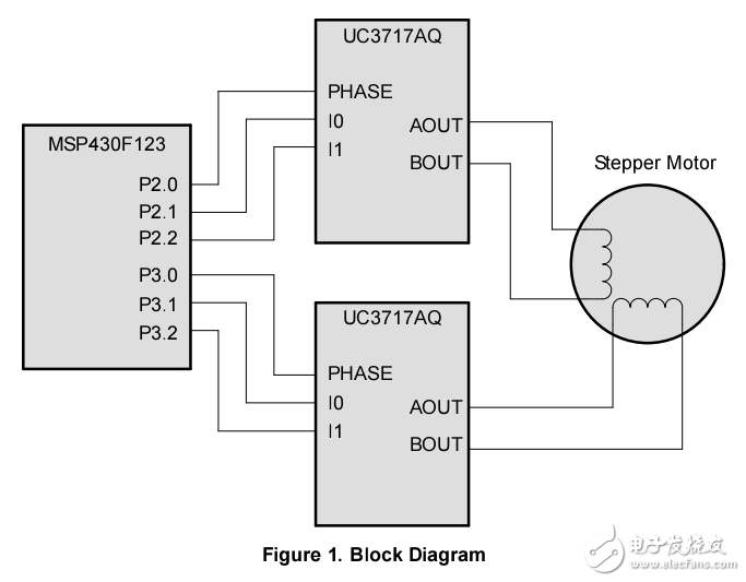
MSP430 Stepper Motor Controller电机控制:步进电机
分享资料个
Stepper motors operate by sequentially energizing coils located in the stator. Depending upon the stepper
motor’s type; variable reluctance, permanent magnet, or hybrid, the rotor contains a toothed soft-iron core,
permanent magnets, or both. What sets a stepper motor apart from other motor types is the ability to step
(or turn) its rotor in small, precise increments and lock it in place
Three configurations are typically found for wiring a stepper motor’s windings; variable reluctance,
unipolar, and bipolar. Each configuration requires different drive circuitry and its associated method of
control. This application report focuses on controlling stepper motors with bipolar windings. Bipolar stepper
motors are driven using an H-bridge circuit since current flow is bi-directional through the windings.
Based on its internal winding resistance, stepper motors are rated for maximum current at a particular
voltage. Maximum torque is developed when maximum current is flowing through the windings. Operating
at this voltage, however, is inefficient due to the ramp-up time it takes for current flow to overcome the
winding‘s inherent inductance. Applying a voltage much higher than it’s rated for to a stepper motor
reduces this ramp-up time. To do this without overheating and destroying the motor, however, the winding
current must still be limited to its maximum rated value. This is done by using a chopper circuit which
controls the ratio of winding current on time to off time once the maximum current level is reached.

声明:本文内容及配图由入驻作者撰写或者入驻合作网站授权转载。文章观点仅代表作者本人,不代表电子发烧友网立场。文章及其配图仅供工程师学习之用,如有内容侵权或者其他违规问题,请联系本站处理。 举报投诉
- 相关下载
- 相关文章


