

使用Simscape Battery和About:Energy实现电池快速充电
描述
电池快速充电时间是电动汽车 (EV) 设计的一个关键性能指标,也是电动汽车客户关注的重点。本文介绍了如何使用 Simscape Battery 以及 About:Energy 开发的自定义电池模型模块和参数为不同电池系统尺寸生成安全且稳健的快速充电配置文件。这包括符合 SAE J1772 的直流 1 级(高达 80 kW)和 2 级(高达 400 kW,也称为 3 级)电池快速充电配置文件。本文还展示了如何使用 Simscape 和 Simscape Battery 的 Battery Pack Builder 工作流程来扩展自定义电池电芯模型(图 1)。工作流程图展示了如何使用 Simscape 将电池电芯组装成用于快速充电应用的电池组。
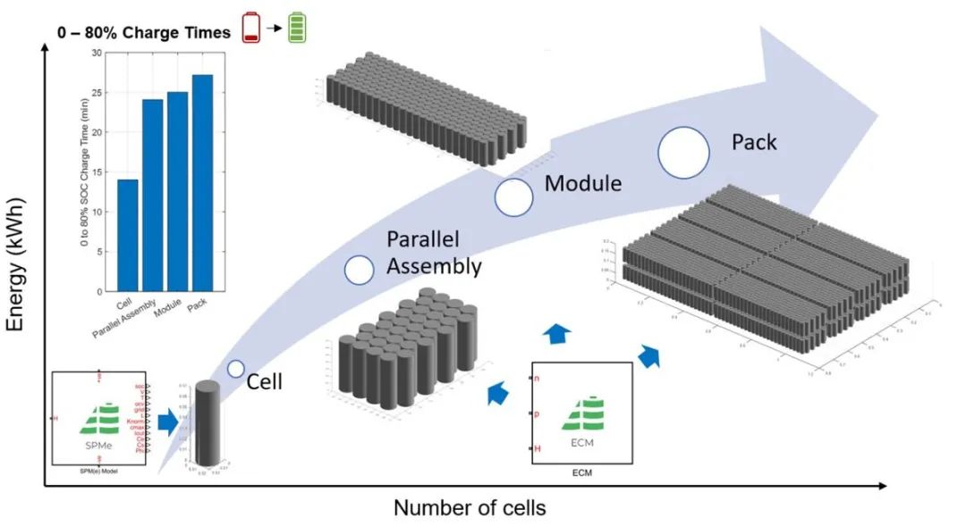
图 1. 使用 Battery Builder 中的自定义 Simscape 电池模型模块实现电池到电池组的快速充电工作流程。
电动汽车锂离子电池电芯内部的几个过程会影响电池的最大充电速率,例如负极中的锂扩散和电解质中的锂离子传输。这些过程发生在微观尺度上,受单个电池的局部温度、充电状态 (SOC) 和健康状态 (SOH) 以及电池化学性质的控制。其他因素也会在电池模块和电池组层面发挥作用,例如系统和直流充电器的电流限制、由于热管理策略导致的电池间温度差异、由于电气设计、控制策略、传感器位置、非电池电阻和制造变化导致的 SOC 差异。这些额外的因素可能会进一步限制快速充电速度。因此,在任何电池设计和验证工作流程中考虑所有这些变量至关重要。
电池电芯模型
Simscape Battery 中的 Battery Builder 功能可以从用户定义的单个电池电芯的Simscape 模块(包括 About:Energy 提供的电池电芯模块)自动创建电池模块和电池组模型。在本文中,我们展示了由 About:Energy 提供的两种先前验证过的富镍高能 2170 电池模型:
- 带电解质的热单粒子模型 (TSPMe),可用于获取内部电化学状态或执行快速充电控制等任务所需的变量。
- 专为快速充电而参数化的等效电路模型 (ECM),一旦扩展到模块或电池组级别,就能提供相对较快的计算时间。
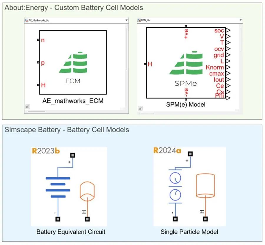
图 2. Simscape 中的基础电池电芯模型模块。
电池到模块工作示例
我们可以使用 Simscape Battery 中的电池构建器功能快速构建电池系统模型的原型,并在各种热和电边界条件和初始运行状态(SOC 和温度)下评估不同子组件级别的电池快速充电时间。首先,我们必须定义一个电池电芯对象,并将该电芯对象链接到 About:Energy 提供的相应电芯模型模块。我们首先扩大 ECM。要使用 ECM 模块,我们首先加载 About:Energy 提供的电热参数,这些参数包含在名为 cellData 的结构体中。
run("CellModelParameters.mlx") % Load cell ECM parameters (e.g., capacity, energy)
要定义电池电芯对象,我们必须实例化 Simscape Battery 中 Battery Builder 包中的 Cell 类:
import simscape.battery.builder.* % Import battery builder package


battCell = Cell(Geometry = CylindricalGeometry(...
    'Height',simscape.Value(cellData.cellHeight,'m'),...
    'Radius',simscape.Value(cellData.cellRadius,'m')), ...
    Capacity = simscape.Value(cellData.cellCapacity,"A*hr"), ...
    Energy = simscape.Value(cellData.cellNominalEnergy,"W*hr")); % Cell object
我们可以通过修改 CellModelOptions 属性将我们的电芯对象链接至 About:Engery 的自定义模块:
 battCell.CellModelOptions.CellModelBlockPath = "AE_Mathworks_lib/AE_mathworks_ECM";
disp(battCell.CellModelOptions)


CellModelBlock with properties:


CellModelBlockPath: "AE_Mathworks_lib/AE)_mathworks_ECM"
    BlockParameters: [1x1 struct]
在这个例子中,我们创建了一个由 16 个电池模块组成的 400 伏汽车式牵引电池。每个电池模块由 36 个圆柱形电池组成,这些电池以并联方式电连接,然后其中 6 个并联组件以串联方式电连接 (36p6s)。将电芯组件放大为并联组件,然后放大为模块的代码如下所示:
battPSet = ParallelAssembly(Cell = battCell, NumParallelCells = 36,...
    Rows = 9, ModelResolution="Detailed",...
    NonCellResistance = "on",...
    AmbientThermalPath="CellBasedThermalResistance", ...
    CoolantThermalPath="CellBasedThermalResistance",...
    CoolingPlate="Bottom"); % Parallel assembly object


battModule = Module(ParallelAssembly = battPSet, NumSeriesAssemblies = 6,...
    NonCellResistance = "on",...
    ModelResolution="Grouped",...
    SeriesGrouping = [1,4,1],...
    ParallelGrouping = [36,1,36],...
    AmbientThermalPath="CellBasedThermalResistance", ...
    CoolantThermalPath="CellBasedThermalResistance",...
    CoolingPlate="Bottom"); % Module object
或者,我们也可以使用 Battery Builder 应用程序定义相同的电池设计和对象(图 3)。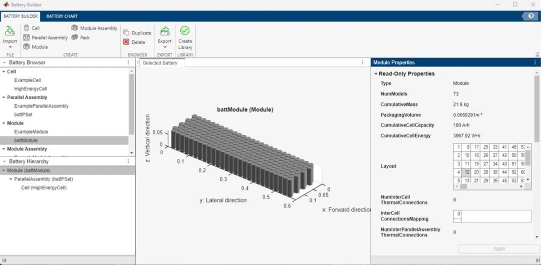
图 3. 用于电池设计的 Battery Builder 应用程序界面。
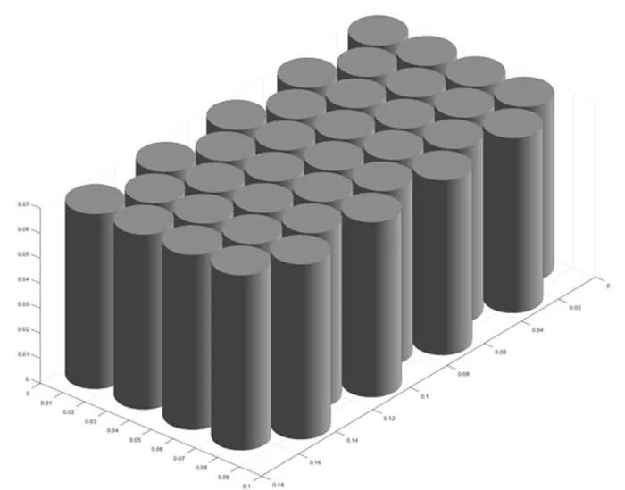
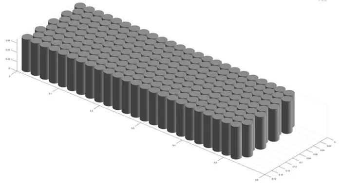
我们可以通过调用 buildBattery 函数从上面定义的电池对象自动生成 Simscape 模型。调用此函数时,我们还可以定义 MaskParameters 名称-值对为“VariableNamesByType”来生成一个包含运行模型所需的所有参数的脚本。在创建模型之前,我们可以使用以下方法验证电池定义和设计:BatteryChart 对象,它有助于在 3D 空间中可视化电池电芯的几何形状和定位。
表 1 展示了我们的模块和并行组装对象使用这些函数的典型输出。
|
电池可视化代码 |
电池模型创建代码 |
|
f = uifigure(Color="w"); BatteryChart(Battery=battPSet);
 |
buildBattery(battPSet, Library= "detailedPSet",... MaskParameters = "VariableNamesByType"); 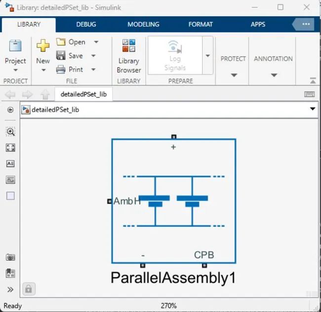 |
|
f = uifigure(Color="w"); BatteryChart(Battery=battModule);
|
buildBattery(battModule, Library= "groupedModule",... MaskParameters = "VariableNamesByType"); 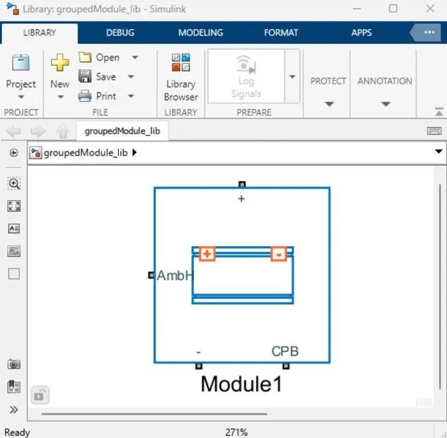 |
表 1. 用于可视化电池对象的代码并在 Simscape Battery 中自动生成模型,这些模型是使用 About:Energy 模块构建的。
接下来,我们定义快速充电电负载,用于测试生成的电池模型。为了实现这一点,我们必须首先评估电池电芯的快速充电能力。
电池级快速充电
在快速充电过程中,根据电池的运行条件及其电化学性质,锂镀层的风险更高。最终,锂沉积背后的关键驱动力是阳极电解质界面处固相和液相之间的局部电位差,该电位差受温度、扩散限制、SOC 和充电速率等多种因素的影响。寒冷的温度通常会导致充电过程中传输现象缓慢和电位差变大。因此,电芯内部温度和 SOC 的差异,自然就会导致电芯不同区域更容易出现锂析出的风险。在特定的电池设计和电池周围的热边界条件下,这些差异总是会存在。
表 2 列出了得出安全快速充电曲线必须考虑的关键内部变量和边界条件。
|
多变的 |
描述和代码 |
|
阳极电位 |
我们将使用负极相对于 Li/Li+ 参比电极的静电势作为锂沉积风险增加和加速降解的指标。在充电过程中,由于电池内部发生的质量传输和化学反应过程,该电位会下降。为了降低锂镀层的风险,该电位不得低于 0 V 太多。在此示例中,该电位阈值将任意设置为 50 mV。 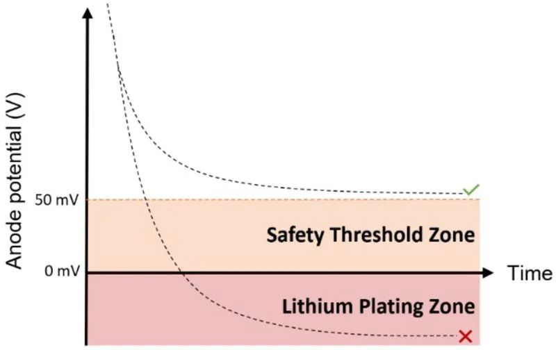 AnodePotentialThreshold = 0.05; % Unit:V |
|
电池温度 |
电池温度必须保持在其运行极限以下,以限制性能下降并降低热失控风险。 TemperatureThreshold = 55 + 273.15; % Unit:K |
|
初始电池温度 |
温度越高,电流就越大。如果达到最高工作温度,这将导致控制系统降低电流并延长充电时间。较低的初始温度可提供更多的温度增量来抑制高热量的产生,但较低的温度也会限制最大电流。因此,存在一个最佳初始温度,可以通过模拟或物理测试找到它。 InitialCellTemperature = 35 + 273.15; % Unit:K |
|
热管理边界条件 |
在此示例中,我们考虑将“底部冷却”电池电芯封装到冷却板上,如下图所示。我们假设从电池底面到冷却通道中的大量冷却剂的热阻恒定为 5 K/W。 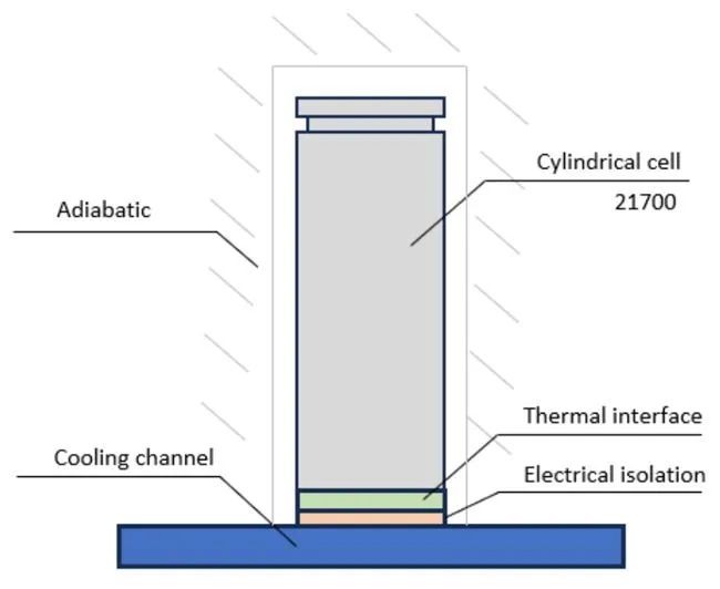 CellThermalPathResistance = 5; % Unit:K/W |
|
电池端电压 |
在充电过程中,电池电压会增加。为防止出现过压或过充情况,电池电压不能超过电池供应商规定的最大值。 MaximumBatteryVoltage = 4.2; % Unit:V |
|
电池充满电 |
在充电阶段结束时,端电压上升至最大值。为了确保最佳快速充电并避免过度充电情况,必须以恒定电压步骤 (CV) 降低电流。在本文中,一旦电流值降至额定电池容量的 1/10 以下,即达到完全充电 (100% SOC)状态。 FullyChargedCurrentThreshold = cellData.cellCapacity/10; % Unit:A |
|
最大充电电流 |
该值应由电池制造商针对一组特定条件(SOC、SOH、温度)指定。一般来说,电池可以在短时间内接受较大的充电电流,在较长时间内接受较小的充电电流。 MaximumChargeCurrent = 30; % @ 0% SOC, instantaneous limit, Unit:A |
表 2. 快速充电模拟的约束、操作条件和边界条件。
快速充电配置文件方法
为了监测整个果冻卷的阳极电位,使用 Simscape 语言和 About:Energy TSPMe 模型作为基础,创建了高度离散化的电热电池级模型(图 4)。热模型沿高度离散化,以捕捉由基底冷却产生的热梯度。离散元件以并联电连接和串联热连接的方式复制电池内部结构并允许更高的内部状态分辨率。通过径向划分元素,可以实现更高、更精确的状态分辨率。About:Energy 还提供 Simscape 2D 热模型模块。
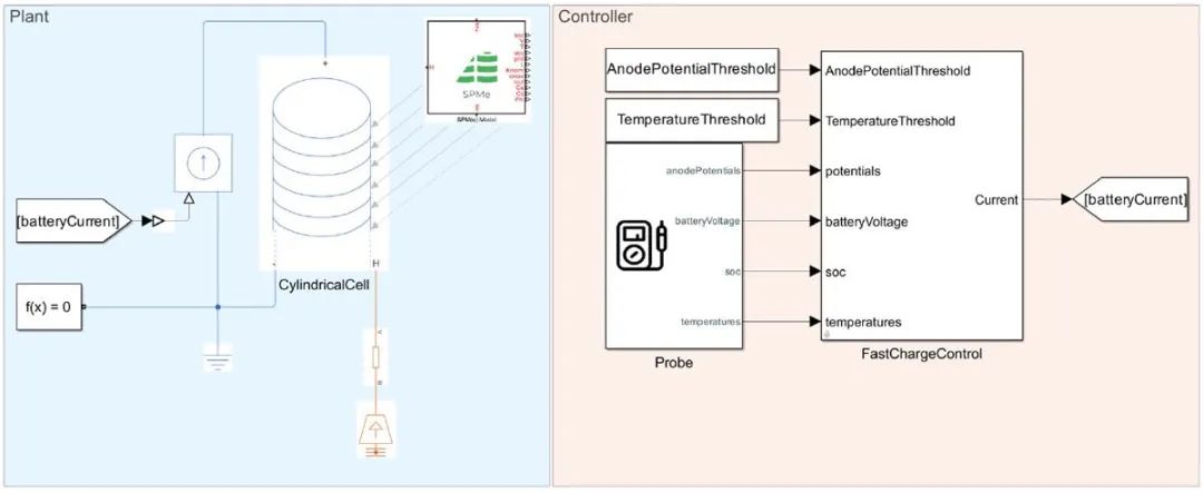
图 4. 使用 Simscape 和 Simulink 创建的离散电池电芯模型。
三个 PI 控制器降低最大允许电流并维持安全运行条件(图 5):
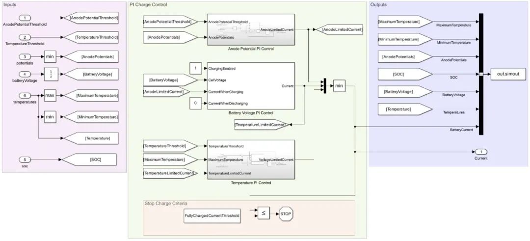
图 5. 离散电池电芯模型的 Simulink 控制策略。
最佳充电电流的推导采用的是这种策略(图 6):
- 在 0% SOC 和选定的初始温度下以供应商允许的最快速度对电池进行充电。
- 如果阳极电位达到其指定的阈值,则降低电流。
- 如果电池电芯上的最热点达到最高工作温度,则降低额定值。
- 如果端电压达到最大电压限制,则降低额定值以防止过度充电。
- 如果有必要,可以根据其他状态添加其他降额条件,例如电解液中的锂浓度。
- 一旦恒定电压阶跃达到 C/10,充电就会停止。
- 将最终传输的电流信号存储为最终的快速充电电流曲线。
cellSimulation = sim("CellLevelFastCharge.slx","StartTime","0","StopTime","3600");
run("PlotCellSimulation.mlx");
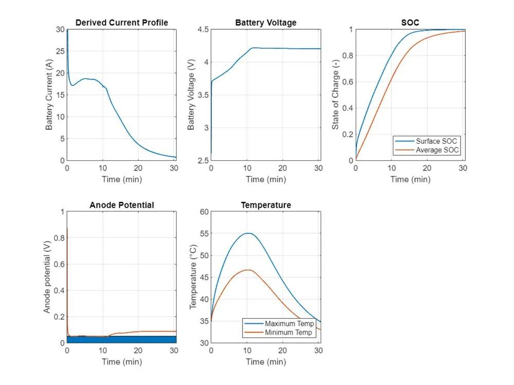
图 6. 离散电池模型模拟的结果。
表 3 总结了根据我们的假设得出的离散化电芯级模拟结果。

表 3. 电池快速充电时间。
电池快充地图
上一节建立的快速充电控制器将输出仅对假设的初始温度和 SOC 有效的电流曲线,并且不考虑这些状态的初始值或动态值的不均匀性。通过在不同的初始条件下运行多次模拟,我们可以得出最大充电电流作为温度和 SOC(寿命开始时)的函数的更通用的二维图。使用Stateflow 逻辑上,对于每一组初始条件,我们都可以运行一个模拟,其中我们将电流从零安培快速增加,直到达到阳极电位阈值或端电压阈值(图 7)。当达到其中一个阈值时,我们会降低电流以使限制变量在给定时间内保持在其阈值上恒定。在本文中,该持续时间将被任意定义为 60 秒(有时称为连续限制),以模拟充电等长时间事件。
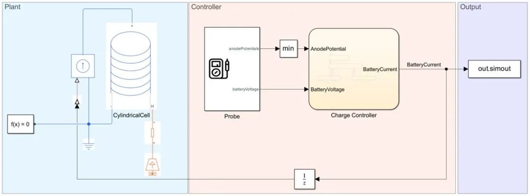
图 7. 离散化电池电芯模型模拟用于获得电池充电电流限制。
一般来说,持续时间越长,电流限制就越低或越严格。模拟在给定的时间范围内停止,然后我们将最终电流值保存为限制(图 8)。生成的地图可以用作我们之前定义的系统级模拟的输入,而该系统级模拟无法访问阳极电位等内部电化学状态。
InitialCellTemperatureVector = [5,15,25,35,45,50] + 273.15; % Unit: K
InitialSOCVector = [0,0.05,0.1,0.2,0.5,0.6,0.8,0.95]; % Unit: -


for initTempIdx = 1:numel(InitialCellTemperatureVector)
    for initSOCIdx = 1:numel(InitialSOCVector)
        InitialCellTemperature = InitialCellTemperatureVector(initTempIdx);
        InitialSOC = InitialSOCVector(initSOCIdx);
        cellSimulations(initTempIdx).SOCPoint(initSOCIdx).Data = sim("CellLevelFastChargeLimitsStateFlow.slx","StartTime","0","StopTime","60");
        cellCurrentLimit(initTempIdx,initSOCIdx) = cellSimulations(initTempIdx).SOCPoint(initSOCIdx).Data.simout.Data(end);
        save cellCurrentLimit
    end
end


newCellCurrentLimit = [cellCurrentLimit, zeros(1,numel(cellCurrentLimit(:,1)))'];


figure("Color","w")
[xq,yq]= meshgrid([550]+273.15, 01);
vq = griddata(InitialCellTemperatureVector,[InitialSOCVector,1],newCellCurrentLimit',xq,yq);
mesh(xq,yq,vq)
xlabel('Temperature (°C)')
ylabel('State of Charge (-)')
zlabel('Current Limit (A)')
view([-5 3.5 5])
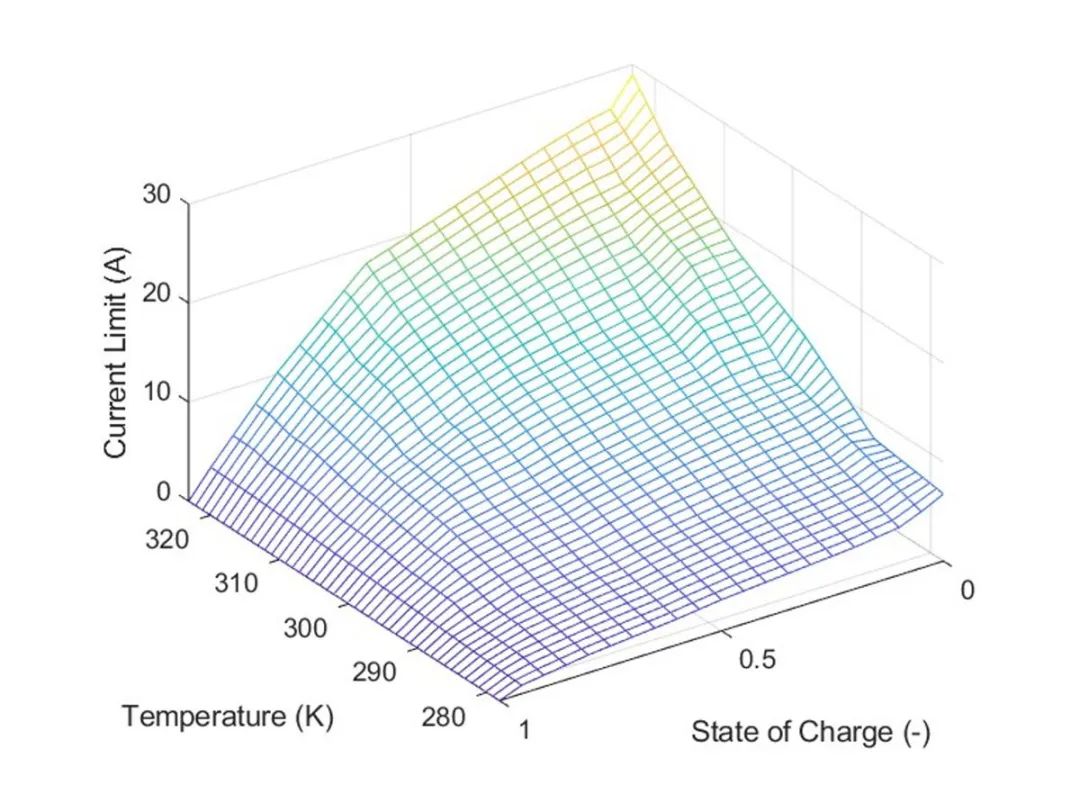
图 8. 连续充电电流限制图作为温度和 SOC 的函数。
并联级快充
在制造电动汽车电池组时,通常首先将电池电芯与其他电池电芯电并联连接以形成并联组件,从而扩大电池容量和能量。要计算并联组装子系统的快速充电曲线,我们只需将获得的电池快速充电曲线乘以并联电池的数量。取决于这个数字 P,产生的快速充电电流可能会超过充电站常见电池直流充电器的最大电流限制。当尝试预测系统级快速充电时间时,这是需要牢记的一个重要约束。如果电池总数量固定,且电池能量特定,则 400 伏电池组的并联电池数量通常会比 800 伏系统更多。如果我们想利用第一部分中得出的最佳电池快速充电曲线,那么并联的电池数量越多,快速充电电流就越大。对于典型的 400 伏系统,更高的电流或 P 数字意味着它们更有可能受到充电站的限制(当以 0% SOC 开始充电时)。这种限制可能导致电池快速充电能力无法得到发挥以及充电速度变慢。表 4 显示了不同直流电动汽车充电器的典型最大电流。

表4. 快速充电器规格。
图 9 显示了增压器电流限制为 500 安培,以及典型的 400 伏和 800 伏系统的典型放大、并联组件级快速充电曲线。由于并联电池数量较多与 400 伏系统相关(对于给定的电池能量),我们将任意定义 “36 P” 并联组件作为 400 伏系统的代表。然后我们将该系统与 "18 P" 并联组件,代表 35°C 下的 800 伏系统。
run("parallelAssemblyProfile.m")
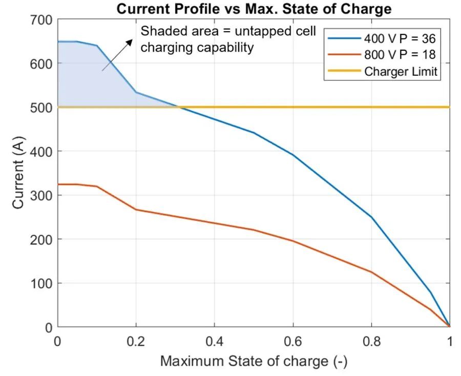
图 9. 35°C 时 800 V 和 400 V 充电曲线比较。
如图所示,400 伏系统最初无法利用电池的所有充电能力,这可能会导致充电时间比预计的 14 分钟内 0-80% 更慢。一般来说,电连接的电池组的充电速率由最冷电池上的最冷点和 SOC 最高的电池内的最高 SOC 点控制。因此,快速充电控制将基于从并行装配厂模型获得的最低电池温度和最高 SOC 信号。电池电芯通常布置在与冷却板(也包含一层电隔离层)接触的热界面材料的顶部。我们将通过假设一些不均匀性(例如,在电池和冷却板之间应用热界面材料)来定义该热路径中的随机变化。
ParallelAssembly1.CoolantResistance = 14 + (30-14)*rand(36,1)'; % Cell level coolant thermal path resistance, K/W
其他需要考虑的重要方面可以使用 Simscape 进行建模,但本文未明确涉及,包括:
- 电池制造过程中电池间内阻和容量的变化。
- 如果设计不当,集电板设计可能会导致轻微的电流不平衡。
- 到环境的热路径不同(这些动态通常较慢)。
- 冷却液控制:通常情况下,电动汽车会配备固定的冷却器或冷却能力(例如 5 千瓦),用于从电池系统(和其他组件)中去除热量。实际的冷却液控制也会对电池快速充电时间产生重要影响。
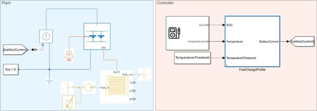
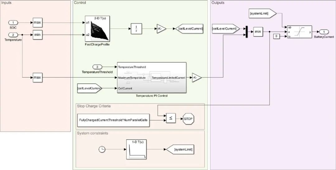
图 10. 并行组装模拟(上)和并行组装快速充电轮廓控制模块(下)。
运行并行装配模拟并绘制结果(图 11)。
run("detailedPSet_param.m");
set_param("ParallelAssemblyLevelFastCharge","SimscapeLogType",'all')
pSetSimulation = sim("ParallelAssemblyLevelFastCharge.slx","StartTime","0","StopTime","5200");
run("PlotParallelAssemblySimulation.mlx"); % Plot results
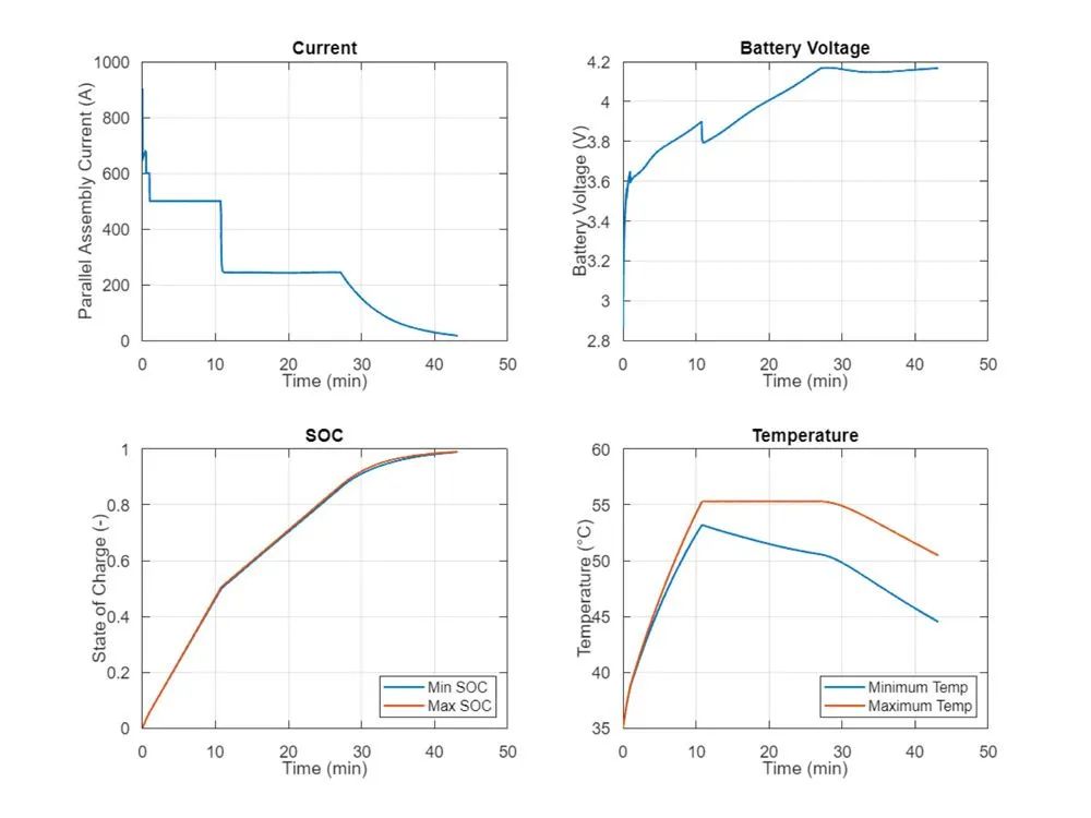
图 11. 平行装配模拟结果。
如摘要图所示,并联组件在模拟开始时受到充电器 500 安培最大电流的限制。此外,最热的电池温度达到 55°C,引发热降额,从而减慢模拟时间。为了可视化电池动态温度,我们可以创建电池模拟日志对象,如下面的代码所示(图 12)。
pSetSimLog = BatterySimulationLog( battPSet, pSetSimulation.simlog.ParallelAssembly1);
pSetSimLog.SelectedVariableUnit = "degC";
f = uifigure("Color","w");
g = uigridlayout(f, [1,1]);
parallelAssemblyChart = BatterySimulationChart(Parent = g, ...
    BatterySimulationLog = pSetSimLog);
parallelAssemblyChartColorBar = colorbar(parallelAssemblyChart);
ylabel( parallelAssemblyChartColorBar, strcat("Cell temperature", " (", pSetSimLog.SelectedVariableUnit,")") ,'FontSize',14 );
parallelAssemblyChartColorBar = colormap(parallelAssemblyChart);
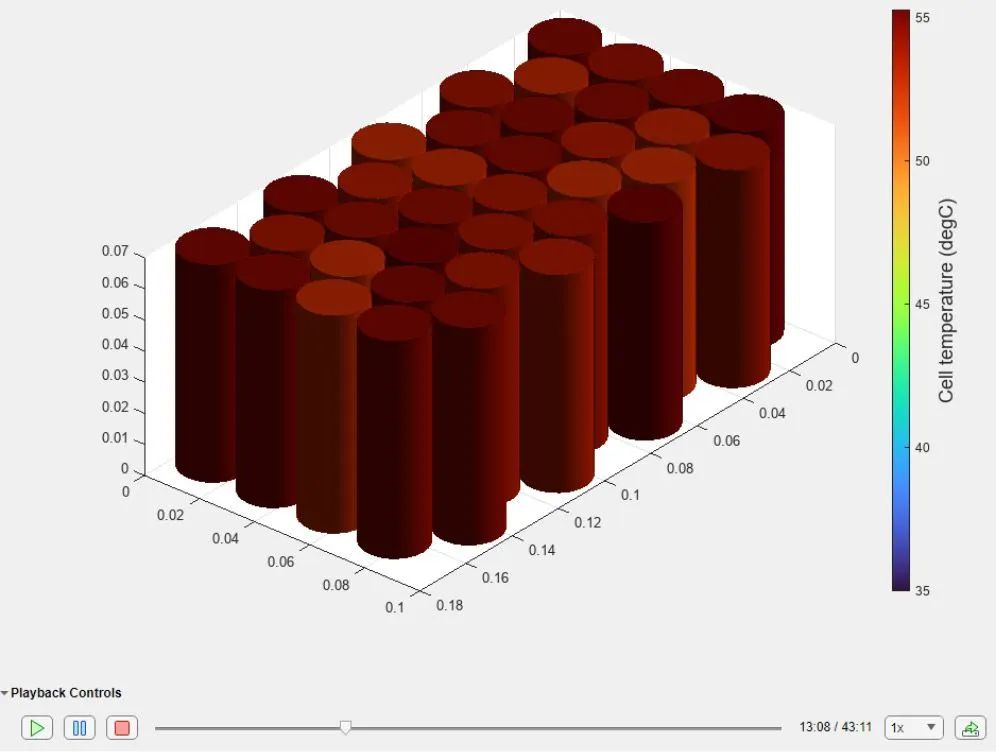
图 12. 平行组装动态 BatteryChart 仿真结果。
如动态电池图所示,电池之间的温差约为 5°C。这种差异主要是由于冷却剂假设的热路径随机变化造成的。表5显示了并行装配模拟结果。0–80% SOC快速充电时间增加了10分钟,这主要是由于系统级限制和热假设。

表 5. 并行组装充电时间。
定制电池块指南(适用版本最高 R2024a)
Simscape Battery 组构建器有一些有效使用自定义电池模块的指导原则:
- 自定义电芯模型不能有名为 power_dissipated 的变量。
- 如果需要热效应,模型必须至少有一个类型为“热域”的端口或节点。
- 如果一个关键的电芯模型模块变量需要在 Simulink 画布中可见(例如,使用 Probe 模块),那么这个变量的 ExternalAccess 必须设置为公共,并且没有任何限制。否则,该变量将仅在后处理的模拟日志中可见。
按照与上述相同的过程,我们可以为上面生成的模块以及更大的电池模块(例如电池组)创建 Simulink 模型。然后,我们可以将这些模块耦合到同一个并行组装充电控制模块,该模块依赖于二维电池充电图。表 6 包含这些模拟的摘要。总体而言,由于温差增大及部分电池温度较高,当前模块和电池组设计中的快速充电时间会略有增加。
|
模型 |
结果/动态电池图表 |
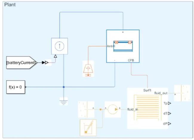 |
0-80%:25 分钟 0-100%:44 分钟 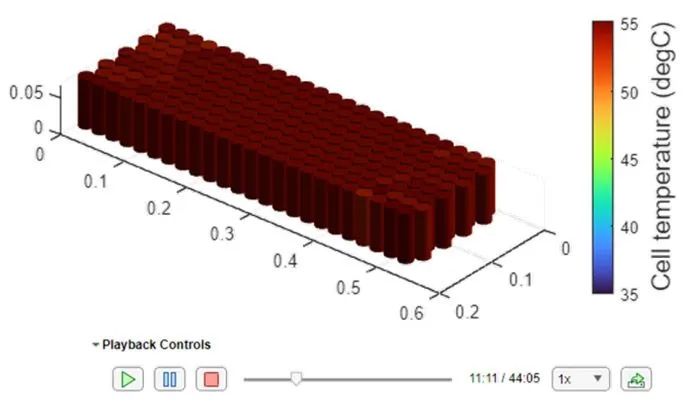 |
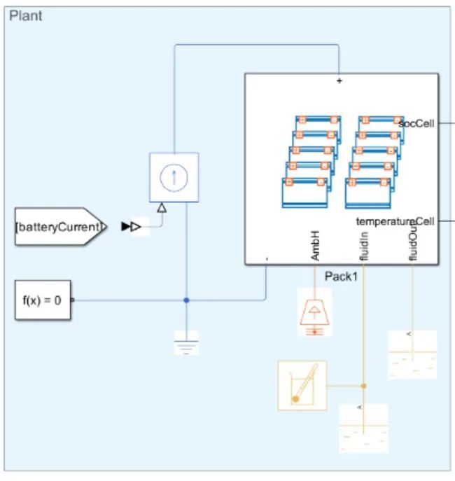 |
0-80%:27 分钟 0-100%:46 分钟 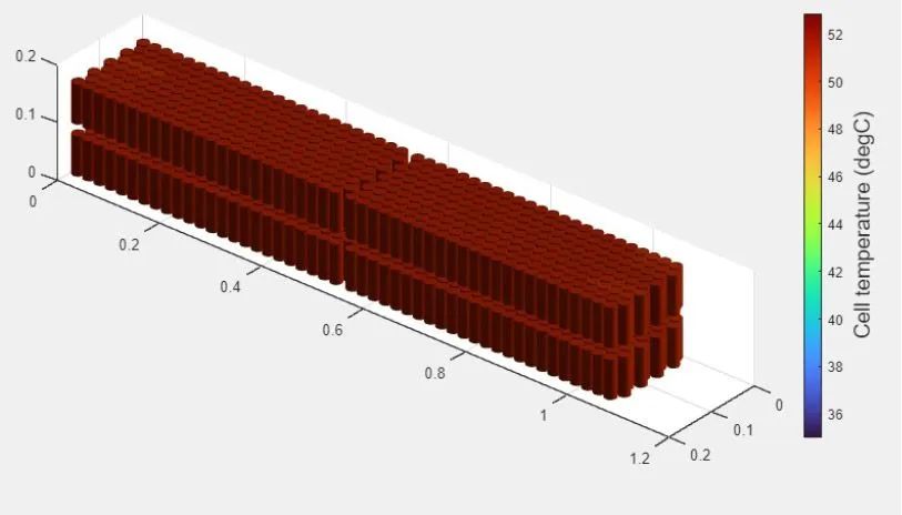 |
表 6. 模块及包快充效果。
结论
我们使用 Simscape Battery 和 About:Energy 模块和参数对电池快速充电时间的调查证明了从单个电池建模到电池组模拟的系统化多尺度方法的重要性。我们强调将 About:Energy TSPMe 和电气模型与 Simscape Battery 支持的详细电池组模型相结合的重要性,以确保电池管理系统的准确性和安全性,促进电池充电领域的持续进步。这些预测的快速充电时间的主要不确定性主要归因于模型分辨率(例如,电热离散化)、建模假设以及所使用的电化学/ECM 模型的准确性。一般来说,模型离散化程度或分辨率越高,结果就越准确。
正如电池到电池组的工作流程所示,电池快速充电时间取决于多种变量,并且电池组设计会产生很大的影响。从电池层面开始,电池电芯的最快充电速度取决于小规模发生的锂扩散和传输过程。在模块和电池组级别,其他变量也变得重要,例如直流充电器电流限制、并联电池数量、电池组标称电压(400 伏对 800 伏)、电池内和电池间温度范围、电池内和电池间 SOC 范围、非电池电阻等等。正如本文所示,这些变量,特别是温差,会对充电率产生重要影响,因此在电池虚拟设计和验证工作流程中考虑它们至关重要。下图显示了本文研究的 400 伏系统的预测电池到电池组快速充电时间(图 13)。
batteries = ["Cell","Parallel Assembly","Module", "Pack"];
batteries0To80ChargeTimes = [ChargeTime0To80 pSetChargeTime0To80  moduleChargeTime0To80 packChargeTime0To80];
batteries0To100ChargeTimes = [ChargeTime0To100 pSetChargeTime0To100  moduleChargeTime0To100 packChargeTime0To100];
figure("Color","w")
subplot(1,2,1)
bar(batteries,batteries0To80ChargeTimes)
ylabel("0 to 80% SOC Charge Time (min)")
grid on
subplot(1,2,2)
bar(batteries,batteries0To100ChargeTimes)
ylabel("0 to 100% SOC Charge Time (min)")
grid on
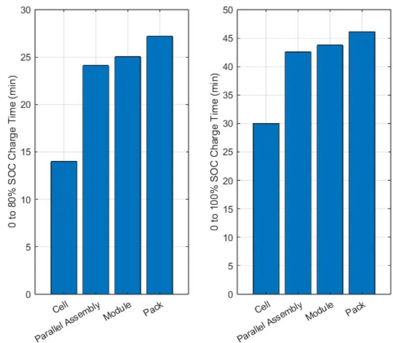
图 13. 电池到电池组的快速充电时间。
-
基于Simscape Battery模型的电池系统建模与仿真2024-09-05 4472
-
电池快速充电指南2023-07-14 2657
-
通过动态电源管理DPM实现快速电池充电的方案2018-11-29 2966
-
自动电池充电器,battery charger2018-09-20 3651
-
基于单片机的常规电池快速充电系统的设计与实现2017-12-07 1161
-
动态电源管理,实现更快速、更高效的电池充电2017-12-06 1371
-
库克为Smart Battery Case充电保护壳深情辩解2015-12-10 4917
-
Energy Micro工具Battery Estimator精确预测电池寿命2011-11-28 1062
-
可充电电池组的保护(Rechargeable Battery2010-08-11 7262
-
汽车电池充电器电路 (Car Battery Charger2009-12-29 2407
-
电池快速充电器的设计与实现2009-11-01 1841
-
电动汽车电池智能快速充电器的设计2009-05-17 14893
全部0条评论

快来发表一下你的评论吧 !

