

Maxim 可穿戴血氧和心率传感器解决方案-MAX86140/MAX86141结构详解
传感器
描述
Maxim公司的MAX86140/MAX86141是超低功耗全集成光学数据采集系统,发送端MAX86140/MAX86141有三个可编程大电流LED驱动器,可驱动多达六个LED;在接收端,MAX86140有单个光学读出通路,而MAX86141有两个能同时工作的光学读出通路.器件的低噪音信号调理模拟前端(AFE)包产到户有19位ADC,业界一流环境光消除(ALC)电路,警戒围栏检测和替代算法.动态范围> 90dB,工作电压1.8V,主要用在可穿戴设备,氧饱和(SpO2)以及肌肉氧饱和(SmO2和StO2).本文介绍了MAX86140/MAX86141主要优势和特性,框图和应用电路,以及MAX86140/MAX86141评估系统主要特性,框图,电路图,材料清单和PCB设计图.
The MAX86140/MAX86141 are ultra-low-power, completely integrated, optical data acquisition systems. On the transmitter side, the MAX86140/MAX86141 have three programmable high-current LED drivers that can be configured to drive up to six LEDs. With two MAX86140/MAX86141 devices working in master-slave mode, the LED drivers can drive up to twelve LEDs. On the receiver side, MAX86140 consists of a single optical readout channels, while the MAX86141 has two optical readout channels that can operate simultaneously. The devices have low-noise signal conditioning analog front-end (AFE) including 19-bit ADC, an industry-lead ambient light cancellation (ALC) circuit, and a picket fence detect and replace algorithm. Due to the low power consumption, compact size, easy/flexible-to-use and industry-lead ambient light rejection capability of MAX86140/MAX86141, the devices are ideal for a wide variety of optical-sensing applications, such as pulse oximetry and heart rate detection.
The MAX86140/MAX86141 operate on a 1.8V main supply voltage and a 3.1~5.5V LED driver supply voltage. Both devices support a standard SPI compatible interface and fully autonomous operation. Each device has a large 128-word built-in FIFO. The MAX86140/MAX86141 is available in compact wafer-level package (WLP)(2.048 x 1.848mm) with 0.4mm ball pitch.
MAX86140/MAX86141主要优势和特性:
Complete Single and Dual-Channel Optical Data Acquisition System
Built-in Algorithm Further Enhances Rejection of Fast Ambient Transients
Optimized Architecture for Transmissive and Reflective Heart Rate or SpO2 Monitoring
Low Dark Current Noise of < 50pA RMS (Sample to Sample Variance)
Lower Effective Dark Current Noise Achievable Through Multiple Sample Modes and On-Chip Averaging
High-Resolution, 19-Bit Charge Integrating ADC
Three Low-Noise, 8-Bit LED Current DACs
Excellent Dynamic Range>90dB in White Card Loop-Back Test (Sample-to-Sample Variance)
Dynamic Range Extendable to > 104dB for SpO2 and > 110dB for HRM with Multiple Sample Modes and On-Chip Averaging
Excellent Ambient Range and Rejection Capability> 100μA Ambient Photodetector Current
> 70dB Ambient Rejection at 120Hz
Ultra-Low-Power Operation for Body Wearable DevicesLow-Power Operation, Optical Readout Channel< 10μA (typ) at 25sps
Short Exposure Integration Period of 14.8μs, 29.4μs, 58.7μs, 117.3μs
Low Shutdown Current = 20μW (typ)
Built-in Algorithm Further Enhances Rejection of Fast Ambient Transients
Miniature 2.048 x 1.848mm, 5 x 4 0.4mm Ball Pitch WLP
-40 ℃ to +85℃ Operating Temperature Range
MAX86140/MAX86141应用:
Wearable Devices for Fitness, Wellness and Medical Applications
Optimized for Wrist, Finger, Ear, and Other Locations
Optimized Performance to DetectOptical Heart Rate
Oxygen Saturation (SpO2)
Muscle Oxygen Saturation (SmO2 and StO2)
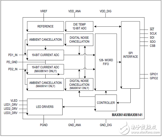
图1.MAX86140/MAX86141简化框图
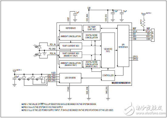
图2.MAX86140/MAX86141典型应用电路图
MAX86140/MAX86141评估系统(EVSYS)
The MAX86140/MAX86141 Evaluation System (EVSYS) allows for the quick evaluation of the MAX86140 and MAX86141 optical AFE for applications at various sites on the body, particularly the wrist. Both MAX86140 and MAX86141 supports standard SPI compatible interface. MAX86140 consists of a single optical readout channels, while MAX86141 has two optical readout channels that operate simultaneously. The EVSYS allows flexible configurations to optimize measurement signal quality at minimal power consumption. The EVSYS helps the user quickly learn about how to configure and use the MAX86140 and MAX86141.
The EVSYS consists of three boards. MAX32620UC-BLEEK# is the main data acquisition board while MAX86140OSBEK# and MAX86141OSBEK# are the sensor daughter boards for MAX86140 and MAX86141 respectively. The EVSYS can be powered using the USB-C supply or LiPo Battery.
The EVSYS comes with a MAX86140ENP+/MAX86141-ENP+ in a 24-bump wafer-level package (WLP).
MAX86140/MAX86141评估系统主要特性:
Quick Evaluation of the MAX86140/MAX86141
Supports Optimization of Configurations
Facilitates Understanding MAX86140/MAX86141 Architecture and Solution Strategy
Real-time Monitoring
Data Logging Capabilities
On-Board Accelerometer
Bluetooth LE
图3. MAX86140/MAX86141评估系统硬件建立图(MAX86140 EVSYS传感器PCB)
图4. MAX86140/MAX86141评估系统硬件建立图(MAX86141 EVSYS Micro PCB)
图5. MAX86140/MAX86141评估系统硬件建立图(MAX86141 EVSYS传感器PCB)
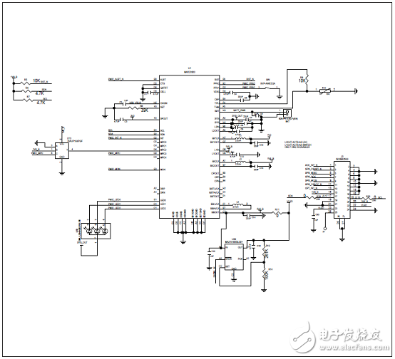
图6. MAX86140/MAX86141评估系统电路图(1):MAX32620UCBLEEK#
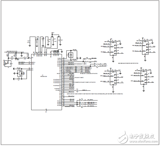
图7. MAX86140/MAX86141评估系统电路图(2):MAX32620UCBLEEK#
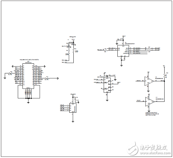
图8. MAX86140/MAX86141评估系统电路图(3):MAX32620UCBLEEK#
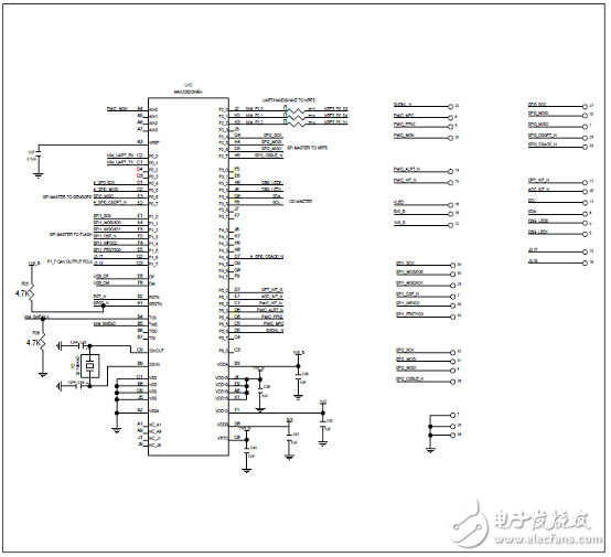
图9. MAX86140/MAX86141评估系统电路图(4):MAX32620UCBLEEK#
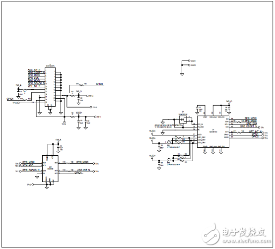
图10. MAX86140/MAX86141评估系统电路图(5):MAX86140OSBEK#
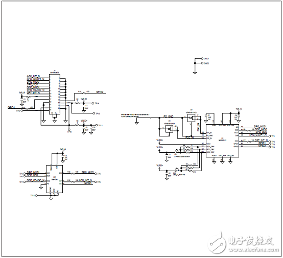
图11. MAX86140/MAX86141评估系统电路图(6):MAX86141OSBEK#
MAX86140/MAX86141评估系统材料清单:MAX32620UCBLEEK#
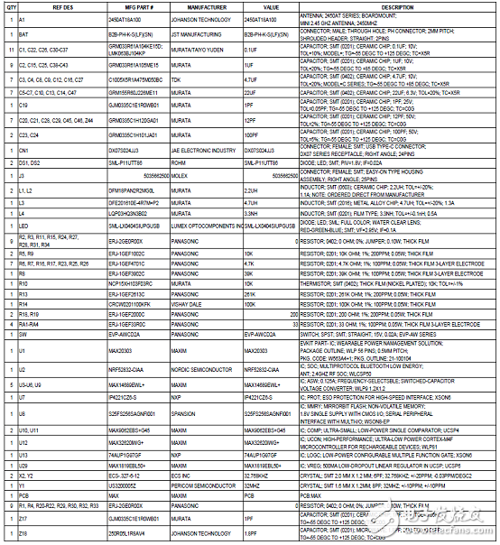
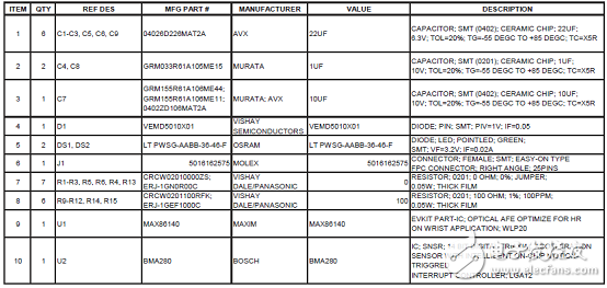
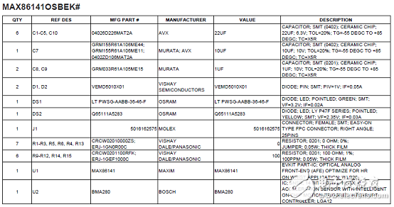

图12. MAX86140/MAX86141评估系统PCB设计图(1): MAX32620UCBLEEK#顶层丝印

图13. MAX86140/MAX86141评估系统PCB设计图(2):
左:MAX32620UCBLEEK#顶层模板右: MAX32620UCBLEEK# L03 SIGS

图14. MAX86140/MAX86141评估系统PCB设计图(3):
左:MAX32620UCBLEEK#顶层 右: MAX32620UCBLEEK# L04 SIGS

图15. MAX86140/MAX86141评估系统PCB设计图(4):
左:MAX32620UCBLEEK# L2 GND 右: MAX32620UCBLEEK# L05 SIGS

图16. MAX86140/MAX86141评估系统PCB设计图(5):
左:MAX32620UCBLEEK# L06 SIGS 右: MAX32620UCBLEEK#底层模板

图17. MAX86140/MAX86141评估系统PCB设计图(6):
左:MAX32620UCBLEEK# L07SIGS 右: MAX32620UCBLEEK#顶层助焊层

图18. MAX86140/MAX86141评估系统PCB设计图(7):
左:MAX32620UCBLEEK#底层 右: MAX32620UCBLEEK#底层助焊层

图19. MAX86140/MAX86141评估系统PCB设计图(8):
左:MAX32620UCBLEEK# L08 SIGS 右: MAX32620UCBLEEK# L10 SIGS

图20. MAX86140/MAX86141评估系统PCB设计图(9):
左:MAX32620UCBLEEK# L11 GND 右: MAX32620UCBLEEK# L09 SIGS
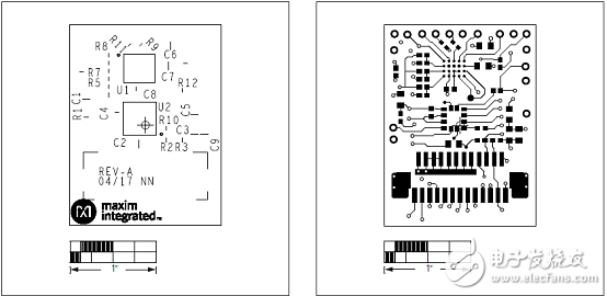
图21. MAX86140/MAX86141评估系统PCB设计图(10):
左:MAX86140OSBEK#顶层丝印 右: MAX86140OSBEK#顶层
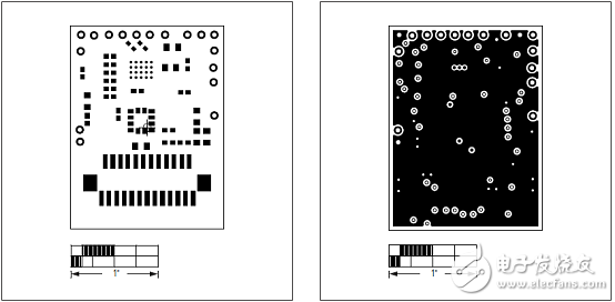
图22. MAX86140/MAX86141评估系统PCB设计图(11):
左:MAX86140OSBEK#顶层模板 右: MAX86140OSBEK# L02 GND
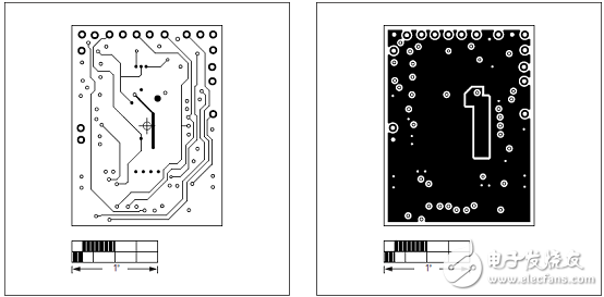
图23. MAX86140/MAX86141评估系统PCB设计图(12):
左:MAX86140OSBEK# L03 GND 右: MAX86140OSBEK# L05 SIG
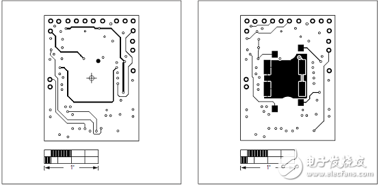
图24. MAX86140/MAX86141评估系统PCB设计图(13):
左:MAX86140OSBEK# L04 SIG 右: MAX86140OSBEK#底层
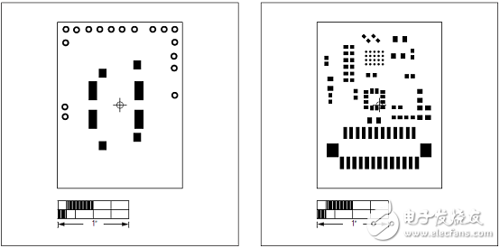
图25. MAX86140/MAX86141评估系统PCB设计图(14):
左:MAX86140OSBEK#底层模板 右: MAX86140OSBEK#顶层助焊层
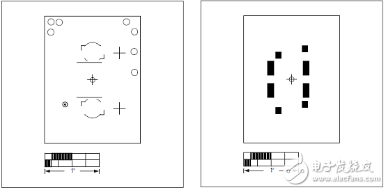
图26. MAX86140/MAX86141评估系统PCB设计图(15):
左:MAX86140OSBEK#底层丝印 右: MAX86140OSBEK#底层助焊层
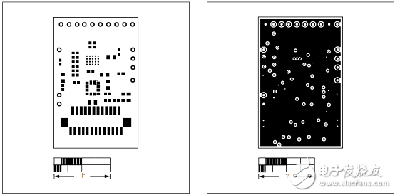
图27. MAX86140/MAX86141评估系统PCB设计图(16):
左:MAX86141OSBEK#顶层模板 右: MAX86141OSBEK# L02GND
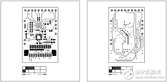
图28. MAX86140/MAX86141评估系统PCB设计图(17):
左:MAX86141OSBEK#顶层 右: MAX86141OSBEK# L03 SIG
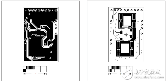
图29. MAX86140/MAX86141评估系统PCB设计图(18):
左:MAX86141OSBEK# L04 SIG 右: MAX86141OSBEK# L05 SIG
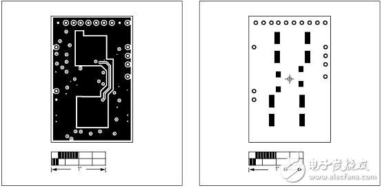
图30. MAX86140/MAX86141评估系统PCB设计图(19):
左:MAX86141OSBEK#顶层 右: MAX86141OSBEK#底层
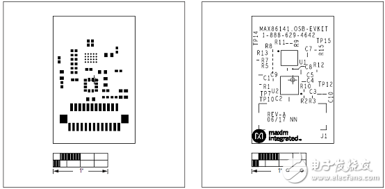
图31. MAX86140/MAX86141评估系统PCB设计图(20):
左:MAX86141OSBEK#顶层助焊层 右: MAX86141OSBEK#顶层丝印
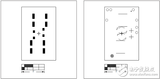
图32. MAX86140/MAX86141评估系统PCB设计图(21)
-
max30102血氧、心率传感器2017-07-24 10678
-
推荐:可穿戴产品 健康传感器平台2020-12-01 2569
-
STM32是如何去MAX30102心率血氧传感器的2021-08-19 3781
-
max30102心率血氧传感器2021-08-20 2721
-
基于MAX30100/MAX30102传感器设计的血氧和心率检测相关资料分享2021-11-10 2349
-
基于MAX30102的心率血氧传感器设计2022-01-13 3085
-
脉搏血氧及心率监测集成传感器模组,为可穿戴应用提供超低功耗方案2016-01-13 3522
-
Maxim积极把握可穿戴设备发展良机,有力支持预防性健康和健身应用2017-11-24 12239
-
基于MAX30102可穿戴血氧和心率生物传感器解决方案2018-06-17 44434
-
如何使用Maxim的腕戴演示平台监测血氧仪和心率2018-10-08 4926
-
MAX86140及MAX86141光学脉搏血氧仪/心率传感器和MAX300012020-03-26 4762
-
MAX86140ENP+T Maxim Integrated MAX8614x脉搏血氧仪和心率传感器2020-10-30 569
-
DFRobot心率血氧传感器有哪些,心率血氧传感器的原理2022-02-22 6815
-
MAX86140-MAX86141: 最佳光脉动脉冲氧化计和穿戴健康数据表的心脏-红传感器 MAX86140-MAX86141: 最佳光脉动脉冲氧化计和穿戴健康数据表的心脏-红传感器2023-10-07 135
-
max30100用于可穿戴健康的脉搏血氧仪和心率传感器IC手册2025-03-24 706
全部0条评论

快来发表一下你的评论吧 !

