

[原创] MicrochipCAN LIN CAN-FD汽车网络开发方案
汽车电子
描述
microchip公司的CAN LIN CAN-FD汽车网络开发板采用8位,16位和32位Microchip MCU系列,提供低成本模块化平台,用于CAN, LIN, CAN-FD网络开发.具有四个mikroBUS™插座,支持CAN和CAN-FD. 7-30V DC电源输入给整个板提供+3.3V和+5V稳压电源.本文介绍了汽车网络开发板主要特性,框图和电路图.
The CAN, LIN, CAN-FD Automotive Networking Development Board provides alow-cost modular platform for CAN, LIN, CAN-FD network development using 8-bit,16-bit, and 32-bit Microchip microcontroller families. It features four mikroBUS™headers to accommodate a variety of plug-in Click™ Board combinations for LIN, CAN,and CAN-FD development. The Automotive Networking Development Board supportsCAN and CAN-FD natively. The CAN digital connection from the microcontrollerconnects to the TX/RX connection on the mikroBUS™ header. This connectionsupports the CAN and CAN-FD Transceiver Click™ boards without having to lose themicrocontroller UART connection to the other mikroBUS™ headers.
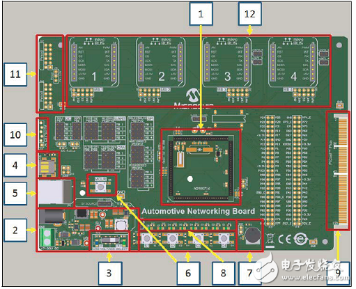
图1.汽车网络开发板外形图
The board includes the key features mentioned below, as indicated in the diagram:
1.100-pin PIM header, compatible with the PIM versions of selected PIC® MCUand dsPIC® DSC devices
2.Direct 7-30V DC power input that provides +3.3V and +5V (regulated) to theentire board
3.Power indicator LED will represent what voltage is applied to the processor PIM.
4.USB connector for connectivity with MCUs that have a USB module
5.Standard 6-wire In-Circuit Debugger (ICD) connector for connections to anMPLAB® ICD programmer/debugger module
6.Push button switches for device Reset and user-defined inputs
7.Potentiometer for analog input
8.Eight indicator LEDs
9.Edge connector for PICtail™ Plus card compatibility
10.Six-pin interface for the PICkit™ Programmer
11.Two Pmod interfaces
12.Four mikroBUS™ headers
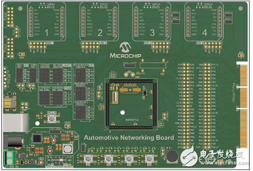
图2.汽车网络开发板正面图
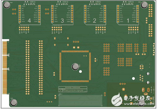
图3.汽车网络开发板背面图
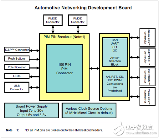
图4.汽车网络开发板框图
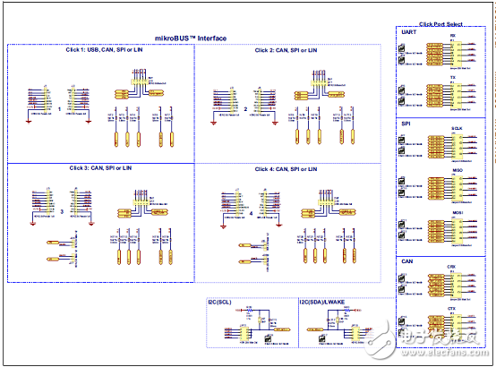
图5.汽车网络开发板电路图(1):mikroBUS接口
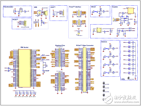
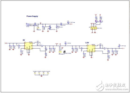
图6.汽车网络开发板电路图(2):PIM连接和分线
-
汽车LIN网络节点互联解决方案2018-12-18 8853
-
应用指南—如何使用DSLogic分析CAN/CAN-FD信号?2023-09-04 4284
-
如何从传统的CAN用法中设置CAN-FD?2025-04-14 3428
-
CAN-FD协议你了解多少2021-08-19 2213
-
一文浅析汽车CAN-FD总线的通信应用2023-02-14 1440
-
多核异构-双核高速率CAN-FD评测2023-02-17 1181
-
什么是汽车远程CAN/LIN网络监控系统2010-03-11 1356
-
CAN、LIN总线在车载网络中的应用2011-06-09 1343
-
你知道CAN-FD协议有多少?2018-07-09 11845
-
CAN-FD协议你了解多少 ?2020-03-08 18264
-
DS70000系列数字示波器在CAN-FD协议解码上的应用2022-03-25 3811
-
简单介绍基于CAN-FD的诊断通信传输层2022-11-10 3666
-
车载CAN-FD的抗扰度评估技术2022-12-14 2476
-
汽车网络架构是什么意思2023-07-18 1759
-
如何使用DSLogic分析CAN/CAN-FD 信号?2024-01-08 3437
全部0条评论

快来发表一下你的评论吧 !
