

基于FPGA的FIFO实现
描述
一、FIFO
1.1 定义
FIFO(First in First out)为先进先出队列,具有存储功能,可用于不同时钟域间传输数据以及不同的数据宽度进行数据匹配。如其名称,数据传输为单向,从一侧进入,再从另一侧出来,出来的顺序和进入的顺序相同。
1.2 实现方式
FIFO可由多种不同的实现方式,可以用块状RAM,分布式RAM来实现,也可直接使用IP核,当数据较小时,建议使用分布式RAM实现,数据较大时,用块状RAM实现。
1.3 实现原理
FIFO组成包含存储单元,写时钟,读时钟,满标志,空标志,读写控制信号,当读时钟和写时钟都是同一个时钟时,则为同步FIFO,否则为异步FIFO。
a.首先,在复位操作后,在写时钟控制下,如果状态非满状态,数据可写入到FIFO中。每写一次数据,写指针加一,写满后将不允许再写入;
b.当FIFO中数据非空时,在读时钟的控制下,数据可从FIFO中读出。每读一次数据,读时钟加一,位于下一个读取的位置,在空状态下,将不能继续读数据;
无论是同步FIFO还是异步FIFO,都是以双口RAM为基础来实现。
二、代码实现
代码为书籍《FPGA应用技术及实践》中5.3.3 FIFO设计中的代码,相比原代码中,对read/write为00时,对count的值变化进行了修改,修改为count<=count更合理,设计为实现4X16的同步FIFO
module FIFO_V(rst,clk,data_in,data_out,read,write,empty,full );
input rst,clk;
input [15:0] data_in;
output reg [15:0] data_out;
input read,write;
output empty,full;
parameter depth=2,max_count=2'b11;
reg empty,full;
reg [depth-1:0] tail;
reg [depth-1:0] head;
reg [depth-1:0] count;
reg [15:0] fifomem [0:max_count];
//读空判断
always@(posedge clk)
begin
if(rst==1)
begin
data_out<=16'h0000;
end
else if(read==1'b1&&empty==1'b0)
begin
data_out<=fifomem[tail];
end
end
//写满判断
always@(posedge clk)
begin
if(rst==1'b0&&write==1'b1&&full==1'b0)
fifomem[head]<=data_in;
end
//写操作
always@(posedge clk)
begin
if(rst==1)
head<=2'b00;
else
begin
if(write==1'b1&&full==1'b0)
head<=head+1;
end
end
//读操作
always@(posedge clk)
begin
if(rst==1)
begin
tail<=2'b00;
end
else if(read==1'b1&&empty==1'b0)
begin
tail<=tail+1;
end
end
//读写操作下的计数
always@(posedge clk)
begin
if(rst==1)
begin
count<=2'b00;
end
else
begin
case({read,write})
2'b00:count<=count;
2'b01:if(count!=max_count) count<=count+1;
2'b10:if(count!=2'b00) count<=count-1;
2'b11:count<=count;
endcase
end
end
//队列空状态判断
always@(posedge clk)
begin
if(count==2'b00)
empty<=1'b1;
else
empty<=1'b0;
end
//队列满状态判断
always@(posedge clk)
begin
if(count==max_count)
full<=1'b1;
else
full<=1'b0;
end
endmodule
测试代码
对于read和write信号,尽量避免在时钟上升沿时进行状态变化,如此处write翻转在201ns,read翻转在#252,即避免了和时钟的上升沿同步,也避免了和write翻转的同步
`timescale 1ns / 1ps
module FIFO_tb( );
reg clk,rst,write,read;
reg [15:0] data_in;
wire [15:0] data_out;
wire empty,full;
FIFO_V FIFO_test (.clk(clk),.rst(rst),.data_in(data_in),.write(write),.read(read),.empty(empty),.full(full),.data_out(data_out));
//初始状态赋值
initial
begin
clk=0;
rst=1;
data_in=16'h1111;
#51 rst=0;
end
//写操作
initial
begin
write=1;
#201 write=1;
#30 write=0;
#200 write=1;
#85 write=0;
//#10 write=1;
//#60 write=0;
end
//读操作
initial
begin
read=0;
#252 read=1;
#200 read=0;
#100 read=1;
end
//输入信号与时钟信号生成
always #20 data_in=data_in+16'h1111;
always #10 clk=~clk;
endmodule
三、仿真结果
3.1 复位阶段
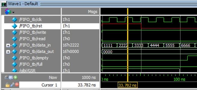
在起始的50ns内,复位信号rst(红色标注)为1时,进行复位操作,如黄色定位线所示,输出data_out为0,empty和full标志为0;
3.2 写入阶段
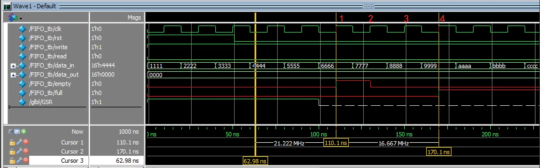
在110.1ns时开始写入,时间点不是110ns而是多了0.1ns是由于modelsim默认的开始时刻是0.1ns开始;因为count原先一直处于初始化状态2'b00,在此时因为写入进行了empty的逻辑判断,因为empty为0;
在clk信号中1、2、3、4上升沿位置,即为写入4个值:6666,7777,8888,9999,写完后刚好写满,因此full标志位在170.1ns处变为1,表示已写满无法再写入。
3.3 读取阶段
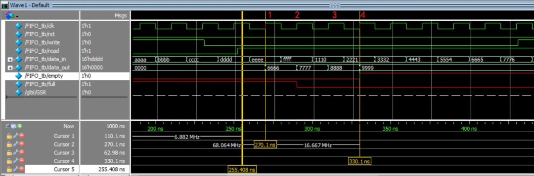
在270.1ns时,read/write的值为1/0开始从FIFO中进行数据读取,在clk信号的1,2,3,4读取了4个数值,根据data_out可知为6666,7777,8888,9999。读出顺序与写入顺序一致,即先入先出。
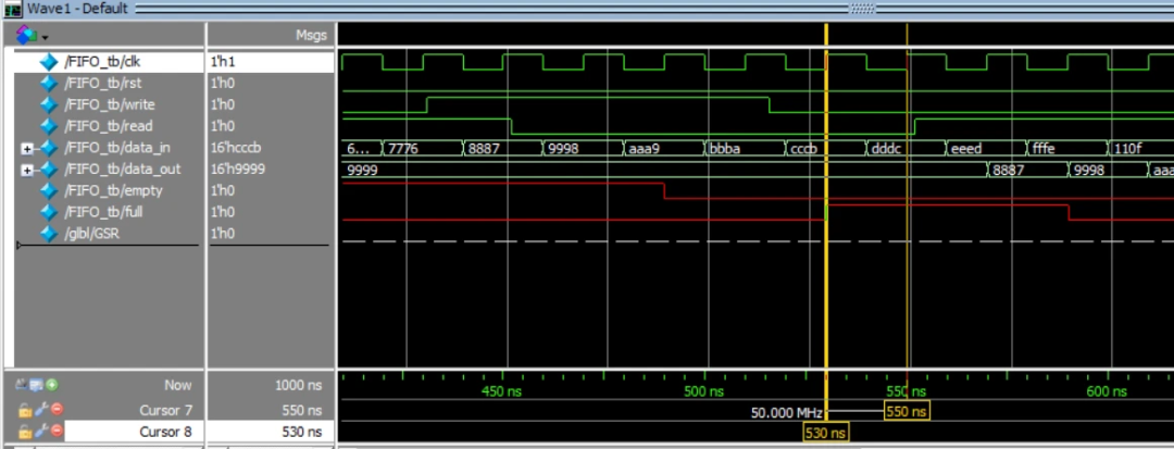
3.4 同时读写或不读不写
在450ns时,read/write都为1,读写同时进行,并且empty为1,可知不进行读操作,count的逻辑。但因full为0,可以进行写入,此时进行写入,在4个clk周期写满,因此在530.1ns时full标志位为1
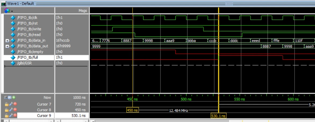
在530ns和550ns时,read/write都为0,此时不读也不写入,因此输出状态不变,一直为9999,
原文链接:https://blog.csdn.net/zyp626/article/details/131620099
-
如何在Altera FPGA中使用FIFO实现功能设计?2021-03-12 4432
-
FPGA电路FIFO设计的源代码2020-07-08 1134
-
在FPGA上实现自行FIFO设计的方法2018-11-28 9959
-
FPGA的FIFO实现过程2018-06-29 16196
-
基于FPGA的异步FIFO的实现2018-06-21 7561
-
异步FIFO在FPGA与DSP通信中的应用解析2017-10-30 1827
-
异步FIFO在FPGA与DSP通信中的运用2011-12-12 1000
-
LabVIEW FPGA模块实现FIFO深度设定2011-09-26 8305
-
基于VHDL和FPGA的非对称同步FIFO设计实现2011-01-13 2386
-
高速异步FIFO的设计与实现2010-01-13 721
-
基于PCI接口芯片外扩FIFO的FPGA实现2010-01-06 773
-
基于FPGA的FIFO设计和应用2009-11-20 2497
-
异步FIFO结构及FPGA设计2009-04-16 833
全部0条评论

快来发表一下你的评论吧 !
