

汽车级音频处理器处理方案
汽车电子
描述
ADI公司的ADAU1462/ADAU1466是汽车级音频处理器,其数字信号处理能力大大超过以前的SigmaDSP®器件.其音频处理算法支持流处理,多速率处理和块处理范例无缝组合,核电压1.2V,32位DSP核工作频率高达294.912 MHz,取样速率48kHz时高达6144 SIMD指令/取样,高达1600ms数字音频延迟池.集成了24KB程序存储器,80KB参数/数据RAM,有四个串行输入端口和4个串行输出端口,主要用在汽车音频处理如音响主机,导航系统,后座娱乐系统,DSP放大器(音响系统放大器),商用和专业的音频处理.本文介绍了ADAU1462/6主要特性,功能框图和系统框图,以及评估板EVAL-ADAU1466Z主要特性,框图,电路图,材料清单和PCB设计图.
The ADAU1462/ADAU1466 are automotive qualified audio processors that far exceed the digital signal processing capabilities of earlier SigmaDSP® devices. They are pin and register compatible with each other, as well as with the ADAU1450/ADAU1451/ADAU1452 SigmaDSP processors. The restructured hardware architecture is optimized for efficient audio processing. The audio processing algorithms support a seamless combination of stream processing (sample by sample), multirate processing, and block processing paradigms. The SigmaStudio™ graphical programming tool enables the creation of signal processing flows that are interactive, intuitive, and powerful. The enhanced digital signal processor (DSP) core architecture enables some types of audio processing algorithms to be executed using significantly fewer instructions than were required on previous SigmaDSP generations, leading to vastly improved code efficiency.
The 1.2 V, 32-bit DSP core can run at frequencies of up to 294.912 MHz and execute up to 6144 SIMD instructions per sample at the standard sample rate of 48 kHz. Powerful clock generator hardware, including a flexible phase-locked loop (PLL) with multiple fractional integer outputs, supports all industry standard audio sample rates. Nonstandard rates over a wide range can generate up to 15 sample rates simultaneously. These clock generators, along with the on board asynchronous sample rate converters (ASRCs) and a flexible hardware audio routing matrix, make the ADAU1462/ADAU1466 ideal audio hubs that greatly simplify the design of complex multirate audio systems.
The ADAU1462/ADAU1466 interface with a wide range of analog-to-digital converters (ADCs), digital-to-analog converters (DACs), digital audio devices, amplifiers, and control circuitry with highly configurable serial ports, I2C, serial peripheral interface (SPI), Sony/Philips Digital Interconnect Format (S/PDIF) interfaces, and multipurpose input/output(I/O) pins. Dedicated decimation filters can decode the pulse code modulation (PDM) output of up to four MEMS microphones. Independent slave and master I2C/SPI control ports allow the ADAU1462/ADAU1466 to be programmed and controlled by an external master device such as a microcontroller, and to program and control slave peripherals directly. Self boot functionality and the master control port enable complex standalone systems.
The power efficient DSP core can execute at high computational loads while consuming only a few hundred milliwatts (mW) in typical conditions. This relatively low power consumption and small footprint make the ADAU1462/ADAU1466 ideal replacements for large, general-purpose DSPs that consume more power at the same processing load. Note that throughout this data sheet, multifunction pins, such as SS_M/MP0, are referred to either by the entire pin name or by a single function of the pin, for example, MP0, when only that function is relevant.
ADAU1462/6主要特性:
Qualified for automotive applications
Fully programmable audio DSP for enhanced sound processing
Features SigmaStudio, a proprietary graphical programming tool for the development of custom signal flows
Up to 294.912 MHz, 32-bit SigmaDSP core at 1.2 V
Up to 24 kWords of program memory
Up to 80 kWords of parameter/data RAM
Up to 6144 SIMD instructions per sample at 48 kHz
Up to 1600 ms digital audio delay pool at 48 kHz
Audio I/O and routing
4 serial input ports, 4 serial output ports
48-channel, 32-bit digital I/O up to a sample rate of 192 kHz
Flexible configuration for TDM, I2S, left and right justified formats, and PCM
Up to 8 stereo ASRCs from 1:8 up to 7.75:1 ratio and 139 dB dynamic range
Stereo S/PDIF input and output at 192 kHz
Four PDM microphone input channels
Multichannel, byte addressable TDM serial ports processing
ADAU1462/6应用:
Automotive audio processing
Head units
Distributed amplifiers
Rear seat entertainment systems
Trunk amplifiers
Commercial and professional audio processing
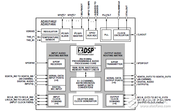
图1.ADAU1462/6功能框图
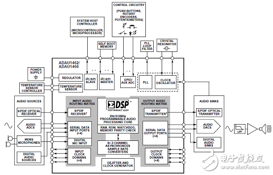
图2.ADAU1462/6带外接元件连接的系统框图
评估板EVAL-ADAU1466Z
This user guide details the design, setup, and operation of the EVAL-ADAU1466Z evaluation board. This device is suitable for evaluation of, and software development for, the ADAU1466 and ADAU1462 SigmaDSP processors. Note that the ADAU1466 and the ADAU1462 are functionally identical, except that the ADAU1466 has more program and data memory than the ADAU1462. When using this evaluation board to evaluate the ADAU1462, in the Setting Up Communications in SigmaStudio section, select the ADAU1462 block rather than the ADAU1466 as shown in Figure 15. Performing this action informs the compiler to limit the amount of memory allocated to match the ADAU1462. All other procedures and instructions in this user guide are identical for the ADAU1462 and ADAU1466.
This evaluation board provides access to the digital serial audio ports of the ADAU1466, as well as some of its general-purpose input/outputs (GPIOs). An analog input and output is provided by the AD1938 codec that is included in the evaluation kit. The ADAU1466 core is programmed using Analog Devices, Inc., SigmaStudio® software, which interfaces to the evaluation board via a USB interface (USBi). The on-board EEPROM can be programmed for self boot mode. The evaluation board is powered by a 6 V dc supply, which is regulated to the voltages required on the board. The printed circuit board (PCB) is a 4-layer design, with a ground plane and a power plane on the inner layers. The evaluation board includes connectors for external analog inputs and outputs, and optical Sony/Philips Digital Interface (S/PDIF) interfaces. The master clock is provided by the integrated oscillator circuit and the on-board 12.288 MHz passive crystal.
评估板EVAL-ADAU1466Z主要特性:
4 analog inputs
8 analog outputs
Stereo S/PDIF input and output
Self boot EEPROM memory
EVALUATION KIT CONTENTS
EVAL-ADAU1466Z evaluation board
EVAL-ADUSB2EBZ (USBi) communications adapter
USB cable with Mini-B plug
6 V ac to dc power supply
图3.评估板EVAL-ADAU1466Z外形图
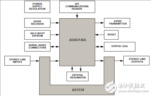
图4.评估板EVAL-ADAU1466Z功能框图
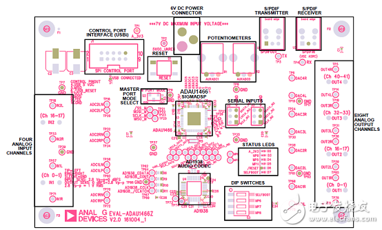
图5.评估板EVAL-ADAU1466Z布局框图
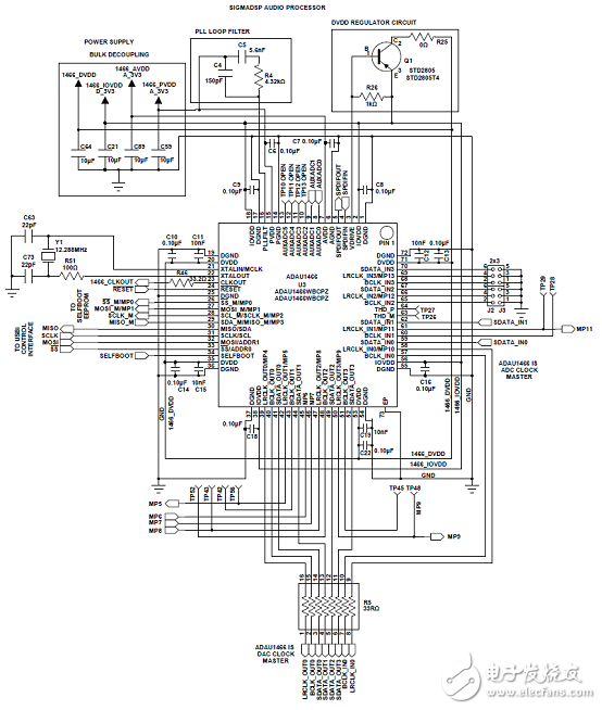
图6.评估板EVAL-ADAU1466Z电路图:SigmaDSP音频处理器
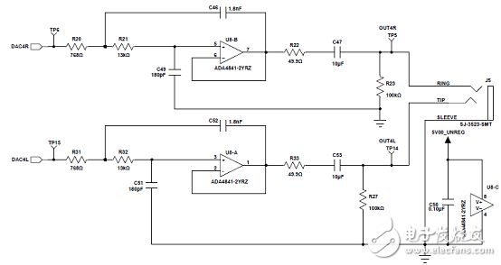
图7.评估板EVAL-ADAU1466Z电路图:自举电路
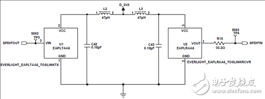
图8.评估板EVAL-ADAU1466Z电路图:S/PDIF光接口
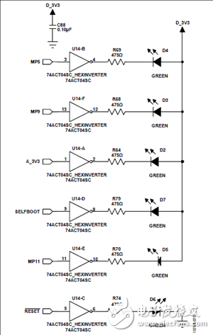
图9.评估板EVAL-ADAU1466Z电路图:静态LED
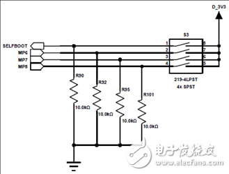
图10.评估板EVAL-ADAU1466Z电路图:DIP开关
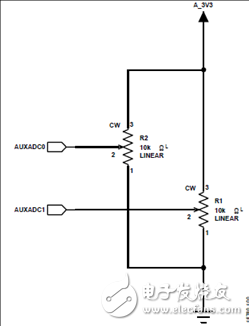
图11.评估板EVAL-ADAU1466Z电路图:AUXADC电位计
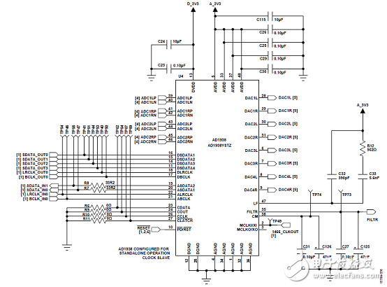
图12.评估板EVAL-ADAU1466Z电路图:AD1938音频CODEC

图13.评估板EVAL-ADAU1466Z电路图:电源
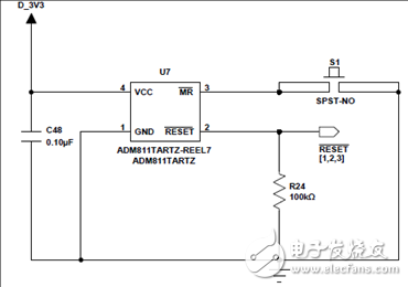
图14.评估板EVAL-ADAU1466Z电路图:重置发生器电路
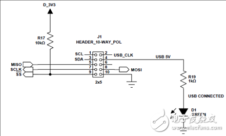
图15.评估板EVAL-ADAU1466Z电路图:SPI通信接口插座
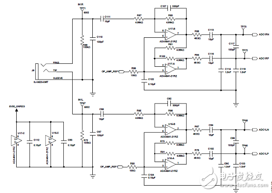
图16.评估板EVAL-ADAU1466Z电路图:模拟输入通路0和1

图17.评估板EVAL-ADAU1466Z电路图:模拟输入通路16和17

图18.评估板EVAL-ADAU1466Z电路图:模拟输出通路0和1
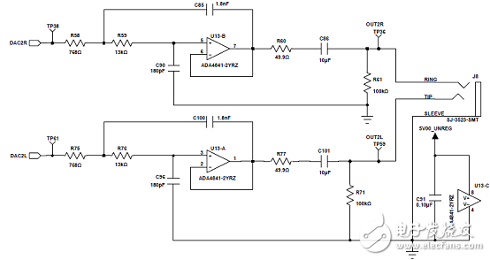
图19.评估板EVAL-ADAU1466Z电路图:模拟输出通路16和17
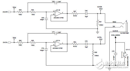
图20.评估板EVAL-ADAU1466Z电路图:模拟输出通路32和33

图21.评估板EVAL-ADAU1466Z电路图:模拟输出通路40和41

图22.评估板EVAL-ADAU1466Z电路图:去耦电容
评估板EVAL-ADAU1466Z材料清单:
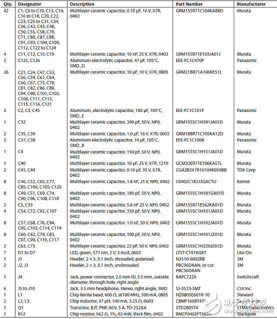
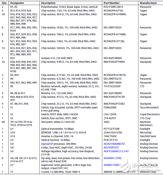

图23.评估板EVAL-ADAU1466Z PCB布局图:顶层装配图
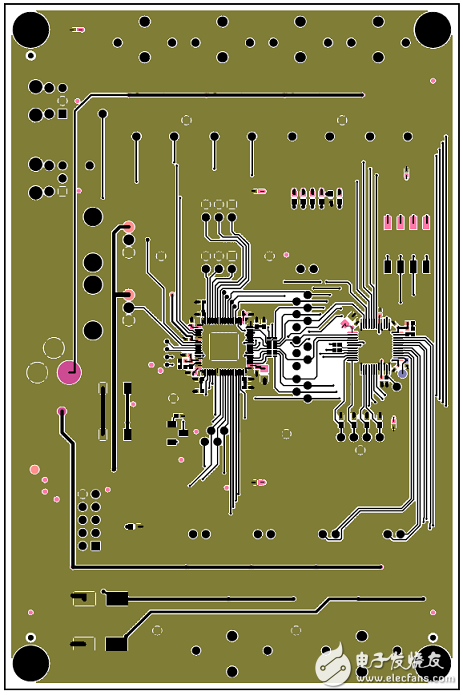
图24.评估板EVAL-ADAU1466Z PCB布局图:顶层铜
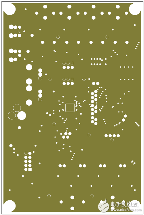
图25.评估板EVAL-ADAU1466Z PCB布局图:地平面
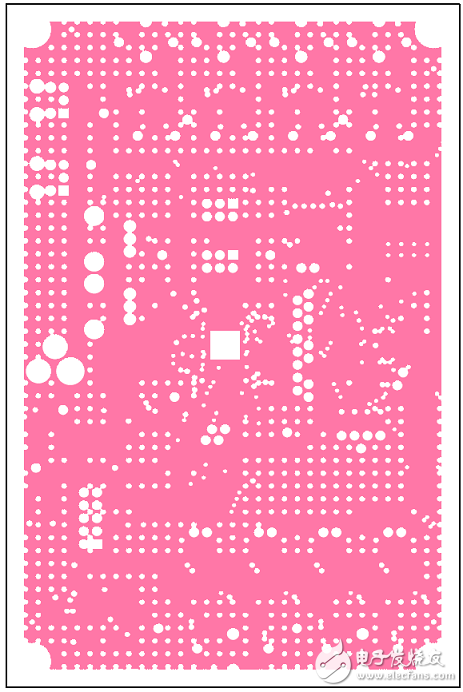
图26.评估板EVAL-ADAU1466Z PCB布局图:电源平面
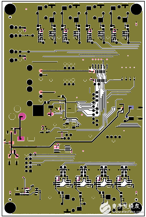
图27.评估板EVAL-ADAU1466Z PCB布局图:底层铜
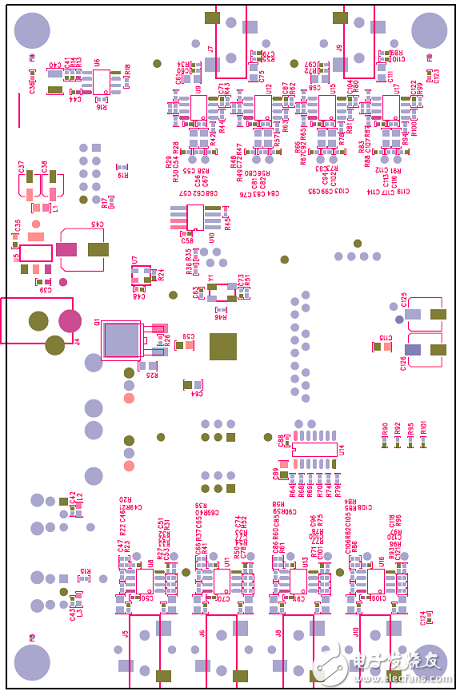
图28.评估板EVAL-ADAU1466Z PCB布局图:底层装配图
-
端侧 AI 音频处理器:集成音频处理与 AI 计算能力的创新芯片2025-02-16 3203
-
细数各种音频处理器2024-07-10 2498
-
音频处理器怎么接线2021-07-29 15714
-
音频处理器的作用_音频处理器和效果器的区别2020-04-09 32231
-
SHARC处理器在音频系统中的典型应用2018-12-29 3504
-
66AK2Gx DSP和ARM处理器音频处理包括BOM及框图2018-10-19 3268
-
音频处理器该如何使用?音频处理器使用方法介绍2018-02-09 39728
-
dsp音频处理器的作用2017-11-15 55383
-
需要音频处理器模块开发方案2017-05-26 3598
-
ARM处理器的音频处理参考设计2017-05-24 1058
-
汽车级音频处理器ADAU1452 有效提高代码效率2014-09-02 12776
-
CONTROLSPACE音频处理器2011-02-27 1461
-
车载娱乐系统的音频处理器2010-12-19 917
全部0条评论

快来发表一下你的评论吧 !

