

MAC57D5xx系列主要特性和高级框图
汽车电子
描述
NXP公司的MAC57D5xx系列产品之用于汽车仪表盘和工业的多核ARM MCU,基于ARM™ Cortex-A5(频率高达320MHz)32位处理器和ARM™ Cortex-A4(频率高达160MHz)32位处理器以及ARM™ Cortex-M0+32位I/O处理器,支持ARMv7- ISA,支持高达2个WVGA分辨率显示,目标应用在汽车电子.本文介绍了MAC57D5xx系列主要特性,高级框图和详细框图,以及包括定制评估板MAC57D5-516DC,适配板MAC57D5-208 (208LQFP和子板MAC57D5-516 (516BGA)在内的MAC57D5xx系列评估板主要特性和电路图.
The MAC57D5xx MCU family is a multi-core architecture solution for mid-range instrument cluster and industrial applications. This MCU is based on the ARM® Cortex®-M processor for real time and an ARM® Cortex®-A processors for applications and human machine interfaces that offer leading edge performance & scalability.
The MAC57D5xx MCU supports up to 2 WVGA resolution displays, one with in line head-up display hardware warping. The graphics content is generated using a powerful Vivante 2D GPU and the 2D animation and composition engine, to reduce memory footprint for content creation, integrated stepper motor drivers and a powerful I/O processor.
The MAC57D5xx MCU integrates NXP®’s latest SHE-compliant CSE2 engine and delivers support ISO26262 ASIL-B functional safety compliance.
MAC57D5xx系列主要特性:
• ARM™ Cortex-A5, 32-bit CPU
– Supports ARMv7- ISA
– 32 KB Instruction cache, 32 KB Data cache
– NEON SIMD Media Processing Engine
– FPU supporting double precision floating pointoperations
– Memory Management Unit
– GIC Interrupt Controller
– Up to 320 MHz
• ARM™ Cortex-M4, 32-bit CPU
– Supports ARMv7 - ISA
– 16 KB Instruction cache, 16 KB Data cache
– 64 KB Tightly-Coupled Memory (TCM)
– Single Precision FPU
– NVIC Interrupts Controller
– 1.25 DMIPS per MHz integer performance
– Up to 160 MHz
• I/O Processor
– ARM™ Cortex-M0+, 32-bit CPU
– Intelligent Stepper Motor Drive
• Memory subsystem
– System Memory Protection Unit
– 4 MB on-chip flash supported with the flashcontroller
– 1 MB on-chip SRAM with ECC
– 1.3 MB on-chip Graphics SRAM with FlexECC
• Supports wake-up from low power modes via theWKPU controller
• On-chip voltage regulator
– External 3.3 V input supply
– Option for direct, external supply of core voltage
– Low Voltage Detect (LVD) and High Voltage
Detect (HVD) on various supplies and regulators
• Debug functionality
– Run-time debug control of cores and visibility ofsystem resources using the Debug Access Port(DAP)
– IEEE 1149.1/ IEEE 1149.7 System JTAG Controller(SJTAG)
– Program and Data Trace support (16-bit data width)implemented by the ARM Trace Port Interface Unit(TPIU) Trace capture
• Timer
– Four 8-channel Flextimer modules (FTM)
– Two 4 channel System Timer Module (STM)
– Three Software WatchDog Timers (SWT)
– One 8 channel Periodic Interrupt Timer (PIT)
– Autonomous Real Time Counter (RTC)
• Analog
– 1 x 24 channel, 12-bit analog-to-digital converter(ADC)
– 2 analog comparators (CMP)
• Security
– Cryptographic Services Engine (CSE)
• Safety
– ISO26262 ASIL-B compliance
– Password and Device Security (PASS) supportingadvanced censorship and life-cycle management
– One Fault Collection and Control Unit (FCCU) tocollect faults and issue interrupts
• Multiple operating modes
– Includes enhanced low power operation
• Memory interfaces
– 2 x Dual QuadSPI Serial flash controllers
– Supports SDR and DDR serial flash
– Support for 3.3 V Hyperflash (Spansion)
– DRAM controller supporting SDR and DDR2
• Clock interfaces
– 8-40 MHz external crystal (FXOSC)
– 16 MHz IRC (FIRC)
– 128 kHz IRC (SIRC)
– 32 kHz external crystal (SXOSC)
– Clock Monitor Unit (CMU)
– Frequency modulated phase-locked loop (FMPLL)
– Real Time Counter (RTC)
• Graphics interfaces
– Vivante GC355 GPU supporting OpenVG 1.1
– 2 x 2D-ACE Display Controllers (with inline Head-Up-Display warping)
– Digital RGB, TCON_0 (RSDS), TCON_1 and OpenLDI/LVDS output options
– Digital Video Input (VIU4)
– RLE Decoder for memory-memory decompression
– 40x4 segment LCD driver, reconfigurable as 38x6 or 36x8
• Cluster peripherals
– Sound Generator Module (SGM)
– 6 Stepper Motor Drivers with Stepper Stall Detect
• Communication
– Ethernet 10/100 + AVB (ENET)
– MLB50
– FlexCAN x 3
– DSPI x 5
– LINFlexD x 3 (1 x Master/Slave, 2 x Master only)
– I2C x 2
• eDMA controller with multiple transfer request sources using DMAMUX
• Boot Assist Flash (BAF) supports internal flash programming
MAC57D5xx系列目标应用:
Automotive
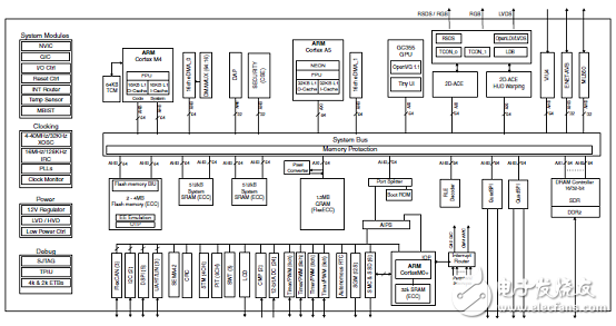
图1.MAC57D5xx系列高级框图
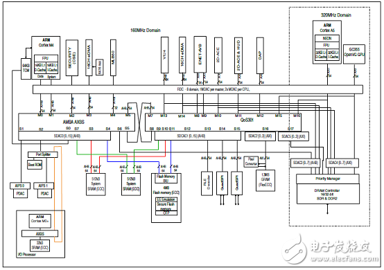
图2.MAC57D5xx系列详细框图
MAC57D5xx系列评估板
1.Customer Evaluation Board [MAC57D5-516DC]
2.Adapter cards MAC57D5-208 (208LQFP)
3.Daughter cards MAC57D5-516 (516BGA)
This user guide details the setup and configuration of the NXPMAC57D5xx Mother Board (MB) Customer EvaluationBoard (hereafter referred to as the EVB) and its daughter cards(208 LQFP and 516 BGA).
The EVB is intended to provide a low cost mechanism forcustomer evaluation of the MAC57D5xx family ofmicrocontrollers, and to facilitate hardware and softwaredevelopment. The EVB is intended for bench / laboratory useand has been designed using ambient temperature specifiedcomponents. Two daughter cards are available which connectto the EVB via high-density connectors. Please consult yourNXP representative for more details.
This product contains components that may be damaged byelectrostatic discharge. Observe precautions for handlingelectrostatic sensitive devices when using this EVB and
associated microcontroller.
Customer Evaluation Board [MAC57D5-516DC]
The NXP® MAC57D5-EVB is an evaluation system supporting both NXP MAC57D5xx microprocessors. The complete system consists of an NXP MAC57D5-EVB motherboard that connects to either one of the following adapter cards: MAC57D5-208 (208LQFP), or MAC57D5-516 (516BGA) daughter cards.
MAC57D5xx系列评估板主要特性:
The MAC57D5MB provides the following key features:
Master Power switch and regulators status LED’s.
High Speed CAN transceiver
LIN interface
Ethernet PHY and RJ45 socket configurable as RMII or MII
20-pin JTAG
ARM Cortex Connector
ART ETM Connector
User RESET switch with reset status LED.
User LED’s
User pushbutton switches
Potentiometer connected to analogue input channel.
VIU Interface
TFT Display interface with Backlight power supply for EastRising - ER-TFT050-3
2 Stepper Motors Connectors
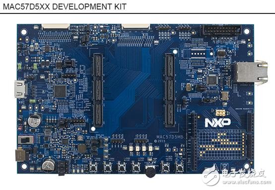
图3.MAC57D5xx系列评估板外形图
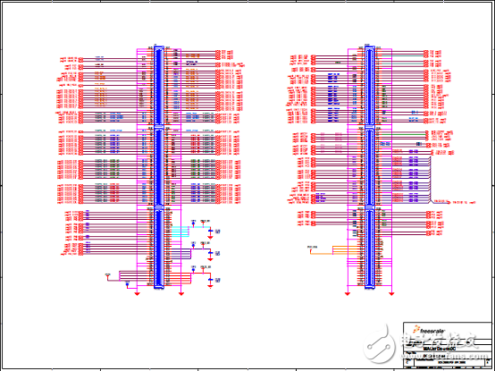
图4.用户评估板MAC57D5-516DC电路图(1)
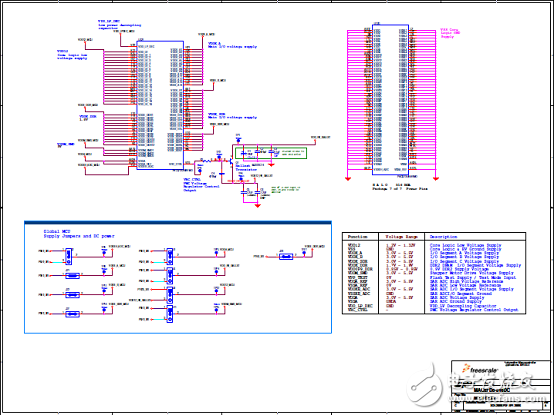
图5.用户评估板MAC57D5-516DC电路图(2)
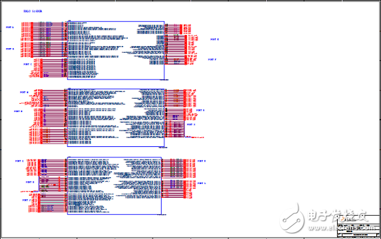
图6.用户评估板MAC57D5-516DC电路图(3)
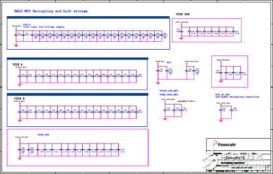
图7.用户评估板MAC57D5-516DC电路图(4)
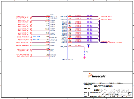
图8.用户评估板MAC57D5-516DC电路图(5)
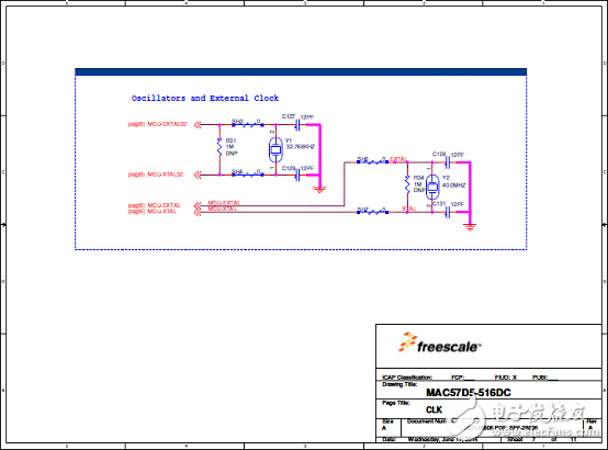
图9.用户评估板MAC57D5-516DC电路图(6)
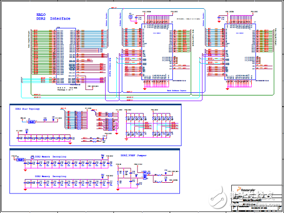
图10.用户评估板MAC57D5-516DC电路图(7)
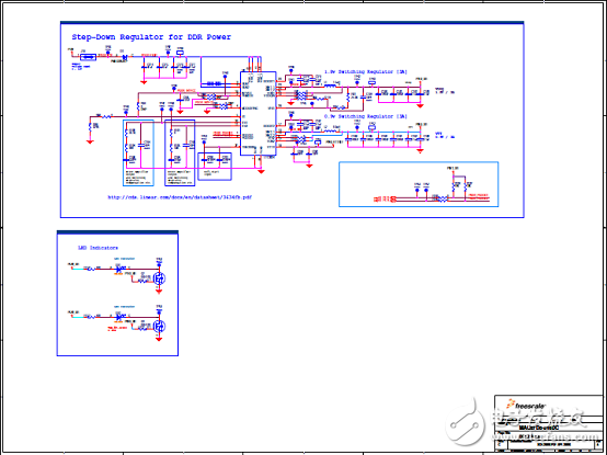
图11.用户评估板MAC57D5-516DC电路图(8)
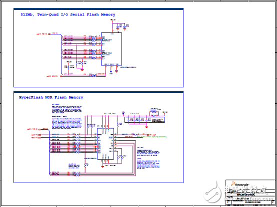
图12.用户评估板MAC57D5-516DC电路图(9)
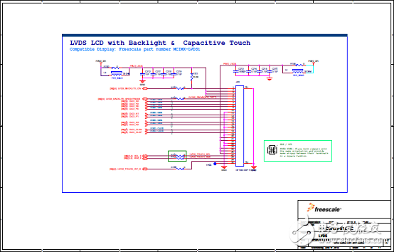
图13.用户评估板MAC57D5-516DC电路图(10)
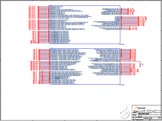
图14.子板MAC57D5-208DC电路图(1)
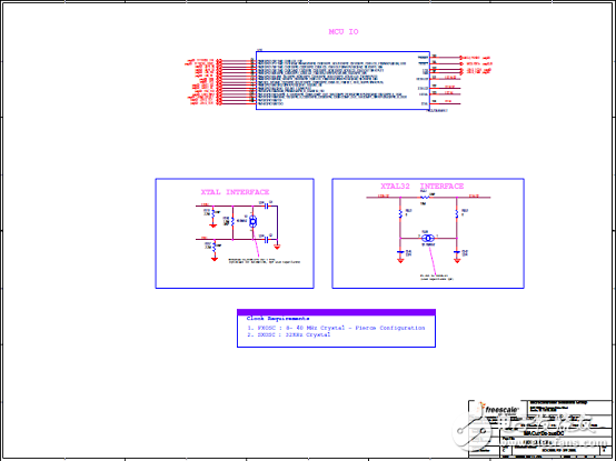
图15.子板MAC57D5-208DC电路图(2)
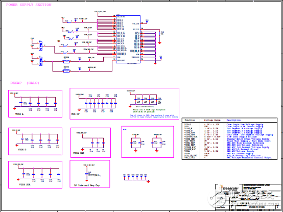
图16.子板MAC57D5-208DC电路图(3)
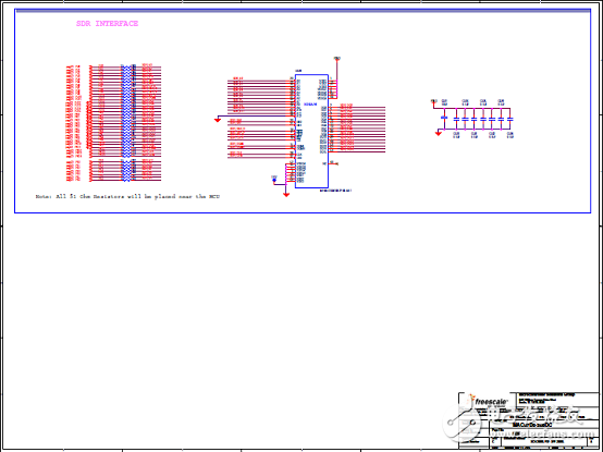
图17.子板MAC57D5-208DC电路图(4)
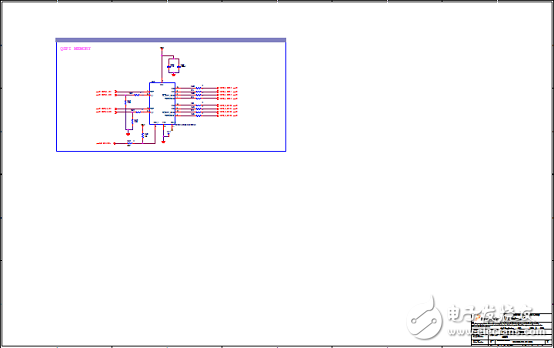
图18.子板MAC57D5-208DC电路图(5)
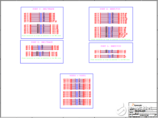
图19.子板MAC57D5-208DC电路图(6)
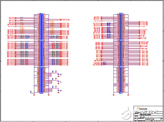
图20.子板MAC57D5-208DC电路图(7)
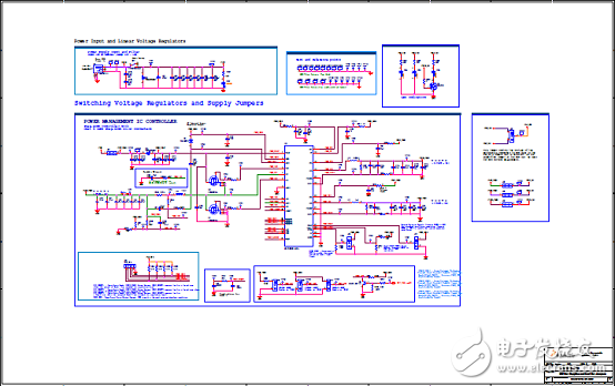
图21.用户评估板电路图(1)
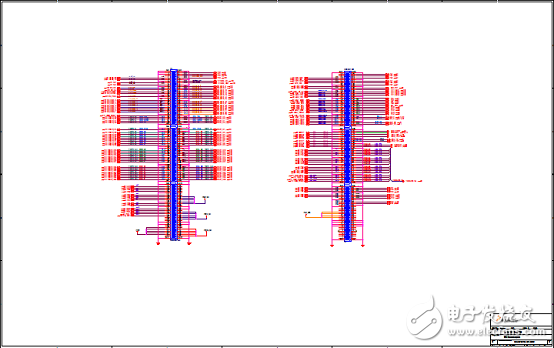
图22.用户评估板电路图(2)
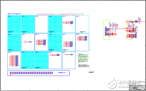
图23.用户评估板电路图(3)
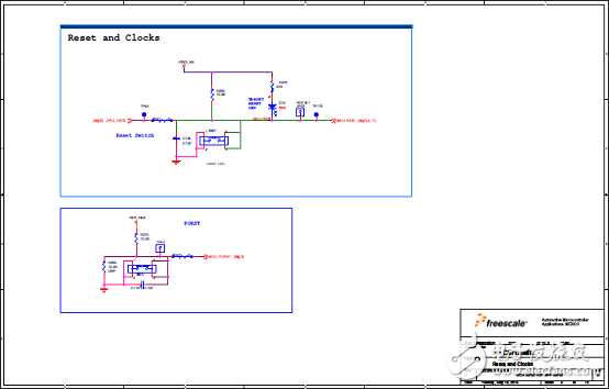
图24.用户评估板电路图(4)
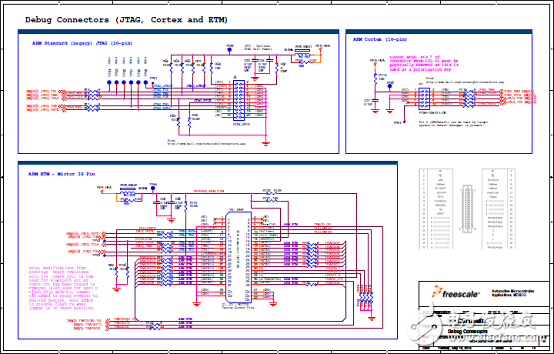
图25.用户评估板电路图(5)
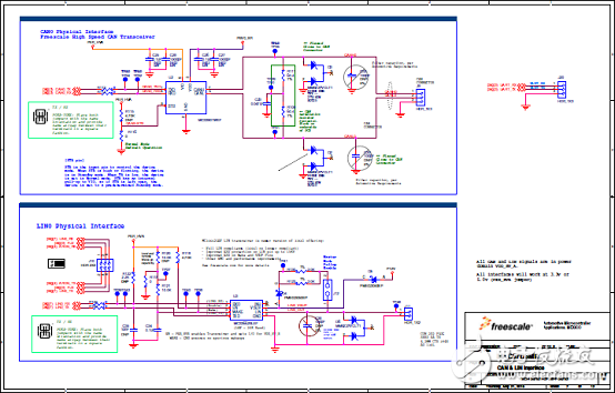
图26.用户评估板电路图(6)
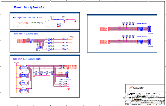
图27.用户评估板电路图(7)
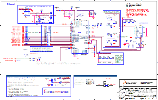
图28.用户评估板电路图(8)
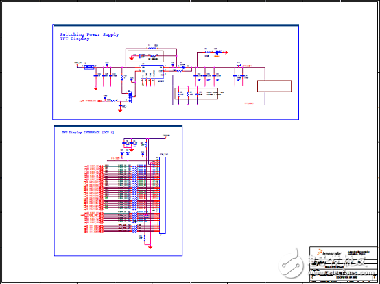
图29.用户评估板电路图(9)
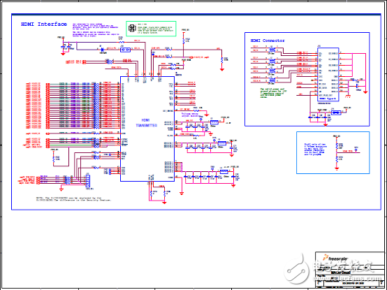
图30.用户评估板电路图(10)
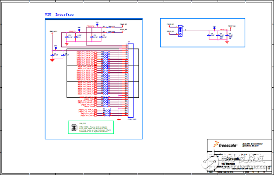
图31.用户评估板电路图(11)
-
MSP430F471xx系列什么? 其主要特性有哪些?2021-05-11 1247
-
PIC32M7xx具有哪些特性参数应用?2021-05-31 1471
-
CS485xx具有哪些特性参数应用?2021-06-01 1027
-
CS470xx系列主要特性是什么?2021-06-02 1400
-
CS470xx具有哪些特性参数应用?2021-06-03 1218
-
TKScope解锁MAC71xx系列芯片JTAG方法2010-07-23 741
-
MAC57D5xx:用于汽车的DIS系列MCU2014-11-10 1623
-
PIC32MZ EF系列处理器主要特性及开发板框图2018-04-14 4929
-
采用单和双高分辨率显示器仪器设备平台 MAC57D5xx系列2018-04-17 1852
-
TCAN1051HGV-Q1主要特性及TCAN10xx系列CAN评估模块主要特性2018-04-27 3604
-
PIC32MZ嵌入连接MCU主要特性和框图分析2018-05-03 6615
-
KIT33905D5EKEVBE主要特性,建立框图,电路图,和PCB元件2018-05-29 2313
-
AD8452主要特性_框图以及应用电路2019-05-11 8792
-
MAC57D5xx系列MCU虚拟仪表盘方案2019-01-18 4369
全部0条评论

快来发表一下你的评论吧 !

