

采用AFE4900可穿戴无线多参数病人监护器参考设计TID-01580详解
电子说
描述
TI公司的AFE4900是超低功耗集成模拟前端(AFE),用于同步化心电图(ECG)和光电血管容积图(PPG)信号收集,也可用于光生物检测应用如心率监测(HRM)和外周血氧饱和度(SpO2)。同步PPG和ECG信号采集数据速率高达1kHz,PPG接收器动态范围高达100 dB.本文介绍了AFE4900主要特性和框图,以及采用AFE4900的可穿戴无线多参数病人监护器参考设计TIDA-01580主要特性,框图,电路图,材料清单和PCB设计图。
The AFE4900 device is an analog front-end (AFE) forsynchronized electrocardiogram (ECG),photoplethysmogram (PPG) signal acquisition. Thedevice can also be used for optical bio-sensingapplications, such as heart-rate monitoring (HRM)and saturation of peripheral capillary oxygen (SpO2)。
The PPG signal chain supports up to four switchinglight-emitting diodes (LEDs) and up to threephotodiodes (PDs)。 The LEDs can be switched onusing a fully integrated LED driver. The current fromthe photodiode is converted into voltage by thetransimpedance amplifier (TIA) and digitized using ananalog-to-digital converter (ADC)。 The ECG signal chain has an instrumentation amplifier (INA) with aprogrammable gain that interfaces to the same ADC.
A right-leg drive (RLD) amplifier set can be used tothe bias for the ECG input pins. AC and dc lead-offdetect schemes are supported. The ADC codes fromthe PPG and ECG phases can be stored in a 128-sample first in, first out (FIFO) block and read outusing either an I2C or a serial programming interface(SPI) interface.
AFE4900主要特性:
• Synchronized PPG, ECG Signal Acquisition atData Rates Up to 1 kHz
• ECG Signal Chain:
– Standalone ECG Acquisition Up to 4 kHz
– Input Bias: 1-Lead ECG With RLD Bias
– Programmable INA Gain: 2 to 12
– Input Noise (1 Hz to 150 Hz): 2.5 μVrms at1 kHz, 1.25 μVrms at 4-kHz Data Rate
– AC, DC Lead-Off Detect: 12.5-nA to 100-nA
• PPG Receiver:
– Supports Three Time-Multiplexed PD Inputs
– 24-Bit Representation of Current From PD
– DC Offset Subtraction DAC (Up to ±126-μA) atTIA Input for Each LED, Ambient
– Digital Ambient Subtraction at ADC Output
– Noise Filtering With Programmable Bandwidth
– Transimpedance Gain: 10 kΩto 2 MΩ
– Dynamic Range Up to 100 dB
– Receiver Operates in PPG-Only mode atApproximately 1-μA/Hz Sampling Rate
– Power-Down Mode: Approximately 0 μA
• PPG Transmitter:
– Four LEDs in Common Anode Configuration
– 8-Bit LED Current Up to 200 mA
– Mode to Fire Two LEDs in Parallel
– Programmable LED On-Time
– Simultaneous Support of Three LEDs forSpO2, or Multiwavelength HRM
– Average Current of 30 μA Adequate for aTypical Heart-Rate Monitoring Scenario:
– 20-mA Setting, 60-μs Pulse Duration,25-Hz Sampling Rate
• Clocking Using an External or Internal Clock
• FIFO With 128-Sample Depth for ECG and PPG
• I2C, SPI™ Interfaces: Selectable by Pin
• Operating Temperature Range: –20℃ to +70℃
• 2.6-mm × 2.1-mm, 0.4-mm Pitch DSBGA Package
• Supplies:
– Rx: 1.8 V to 1.9 V (LDO Bypass),
2.0 V to 3.6 V (LDO Enabled)
– Tx: 3 V to 5.25 V
– IO: 1.7 V to Rx_SUP
AFE4900应用:
• Synchronized PPG, ECG for Blood PressureEstimation
• HRM for Wearables, Hearables
• Heart-Rate Variability (HRV)
• Pulse Oximetry (SpO2) Measurements
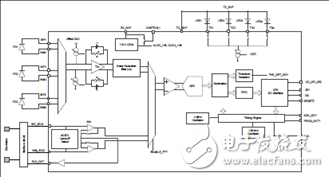
图1.AFE4900简化框图
可穿戴无线多参数病人监护器参考设计TIDA-01580
TIDA-01580 Wearable, Wireless, Multi-Parameter Patient Monitor Reference Design This reference design is a simple, wearable, multiparameter,patient monitor that uses a single-chip,biosensing front end, the AFE4900 device, forsynchronized electrocardiography (ECG) andphotoplethysmography (PPG) measurements. Themeasured data is transferred to a remote locationusing the CC2640R2F device (supporting BLE 4.2 and5)。 The reference design is operated using a singleCR3032 battery and provides a battery life of 30 days.
The raw data is available for the user to calculateheart rate, oxygen concentration in blood (SpO2),pulse-transit time (PTT), and ECG. Two onboard lightemittingdiodes (LEDs) indicate low-battery detectionand ECG lead-off detection for users.
病人监护器参考设计TIDA-01580主要特性:
• Simple, Wearable, Multi-Parameter, Patient Monitorfor PPG and ECG
• Provides Raw Data to Calculate Heart Rate, SpO2,and PTT
• Uses Single-Chip, Biosensing Front-End AFE4900Device for Synchronized ECG and PPGMeasurements
– PPG (Optical Heart-Rate Monitoring and SpO2)Supports Four LEDs and Three Photodiodes(PDs), With Digital Ambient Subtraction toImprove Signal-to-Noise Ratio (SNR)
– ECG (LEAD I) Signals
• Integrated Arm® Cortex®-M3 and 2.4-GHz RFTransceiver (CC2640R2F) Supports Wireless DataTransfer – BLE 4.2 and 5.0
• Operated By CR3032 (3-V, 500-mA Coin-CellBattery), With Battery Life of 30 Days Using HighlyEfficient DC/DC Converters
• Small Form Factor Helps With Easy Adaptation toWearable Applications
病人监护器参考设计TIDA-01580应用:
• Wireless Patient Monitor
• ECG
• Pulse Oximeter
• Wearable Fitness and Activity Monitor
图2.病人监护器参考设计TIDA-01580外形图
图3.病人监护器参考设计TIDA-01580 PCB顶视图(无电池夹头)
图4.病人监护器参考设计TIDA-01580 PCB底视图
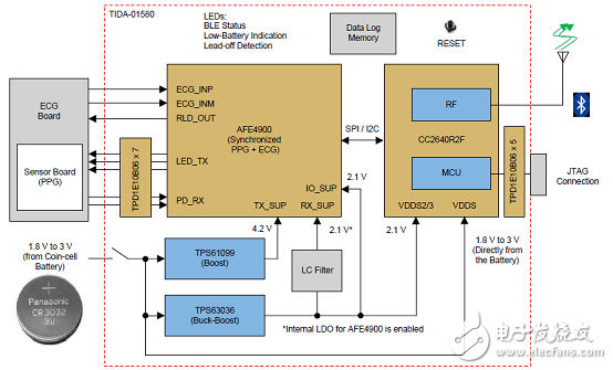
图5.病人监护器参考设计TIDA-01580框图
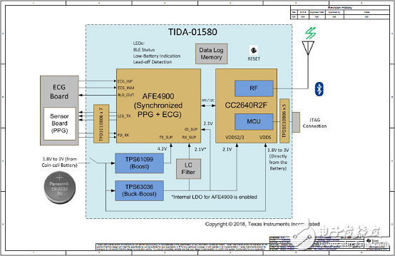
图6.病人监护器参考设计TIDA-01580主电路图(1)
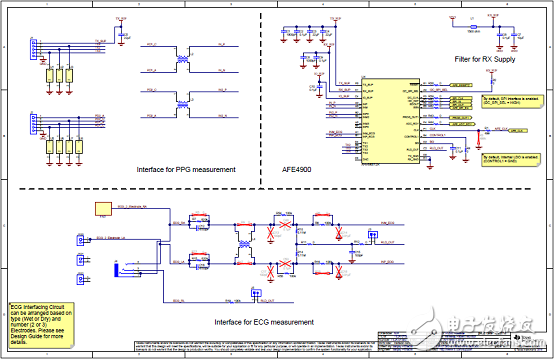
图7.病人监护器参考设计TIDA-01580主电路图(2)

图8.病人监护器参考设计TIDA-01580主电路图(3)
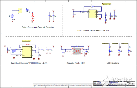
图9.病人监护器参考设计TIDA-01580主电路图(4)
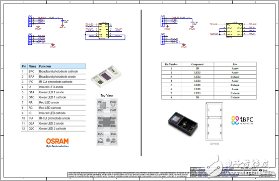
图10.病人监护器参考设计TIDA-01580传感器电路图
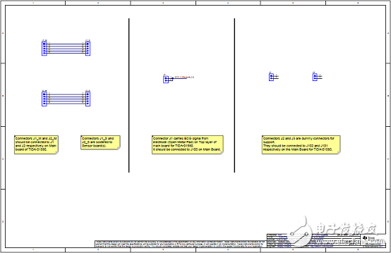
图11.病人监护器参考设计TIDA-01580 ECG电路图
病人监护器参考设计TIDA-01580材料清单:
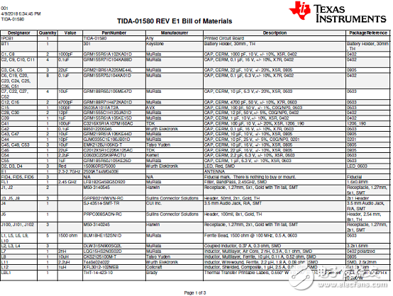
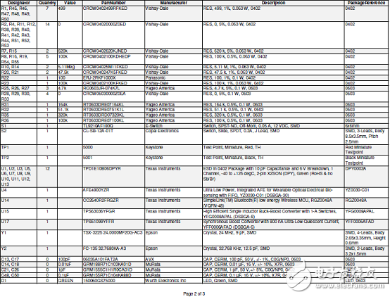

病人监护器参考设计TIDA-01580传感器材料清单:

病人监护器参考设计TIDA-01580 ECG材料清单:

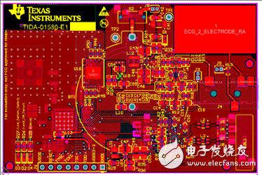
图12.病人监护器参考设计TIDA-01580 PCB设计图(1):顶层
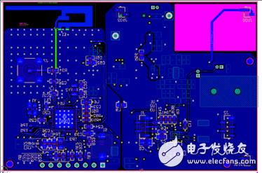
图13.病人监护器参考设计TIDA-01580 PCB设计图(2):底层
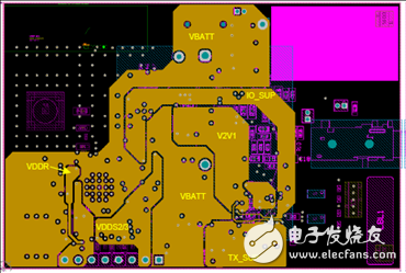
图14.病人监护器参考设计TIDA-01580 PCB设计图(3):电源层
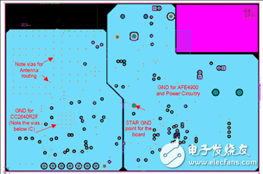
图15.病人监护器参考设计TIDA-01580 PCB设计图(4):地层
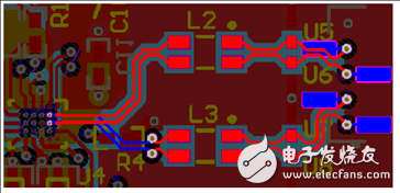
图16.病人监护器参考设计TIDA-01580 PCB设计图(5):PD到AFE走线
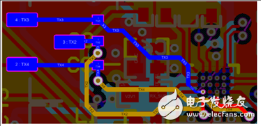
图17.病人监护器参考设计TIDA-01580 PCB设计图(6):LED到AFE走线
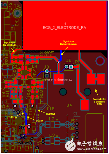
图18.病人监护器参考设计TIDA-01580 PCB设计图(7):ECG PAD到AFE走线
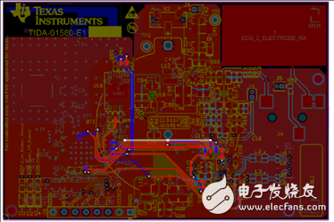
图19.病人监护器参考设计TIDA-01580 PCB设计图(8):CC2640R2F和AFE4900间走线
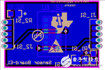
图20.病人监护器参考设计TIDA-01580 PCB设计图(9):CC2640R2F和天线间走线
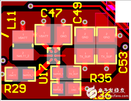
图21.病人监护器参考设计TIDA-01580 PCB设计图(10):升压转换器TPS61099布局和走线
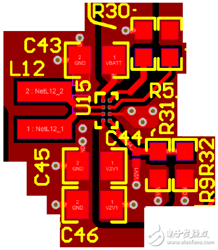
图22.病人监护器参考设计TIDA-01580 PCB设计图(11):降压-升压转换器TPS63036布局和走线
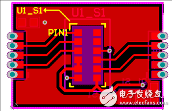
图23.病人监护器参考设计TIDA-01580 PCB设计图(12):SFH7072板布局(顶层)

图24.病人监护器参考设计TIDA-01580 PCB设计图(13):SFH7072板布局(底层)
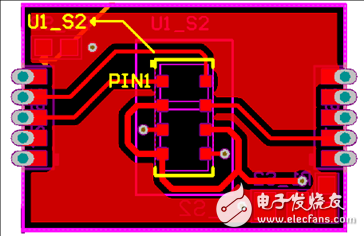
图25.病人监护器参考设计TIDA-01580 PCB设计图(14):OCS112板布局(顶层)
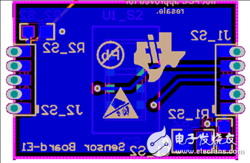
图26.病人监护器参考设计TIDA-01580 PCB设计图(15):OCS112板布局(底层)
图27.病人监护器参考设计TIDA-01580 PCB设计图(16):ECG板布局(顶层)
图28.病人监护器参考设计TIDA-01580 PCB设计图(17):ECG板布局(底层)
-
AFE4900的PPG信号能否用于血压的监测?2024-12-13 310
-
AFE4900的SEN引脚一定要拉低或拉高吗?可以浮空吗?2024-12-09 376
-
请问各位大佬AFE4900 EVM的通信协议是什么?2024-11-29 260
-
AFE4900光学结构如何设计?2024-11-28 267
-
AFE4900是否能够实现FNIR的功能?2024-11-20 287
-
AFE4900超低功耗、集成式AFE数据表2024-07-31 530
-
具有FIFO的AFE49002022-03-02 764
-
基于ZigBee可穿戴传感器的医疗监护系统设计2020-05-11 2688
-
可穿戴无线多参数患者监护仪包括BOM及框图2018-10-18 3174
-
基于ZigBee可穿戴传感器的医疗监护系统2015-09-07 6628
-
【工大物联】基于zigbee的可穿戴式人体体温心电监测腕表2014-12-30 6504
-
多生理参数病人监护2014-08-26 6095
-
求基于labview的多参数病人监护仪的设计2013-05-28 2111
全部0条评论

快来发表一下你的评论吧 !

