

MOORE型有限状态机的设计方案分析
描述
1 、引言
随着微电子技术的迅速发展,人们对数字系统的需求也在提高。不仅要有完善的功能,而且对速度也提出了很高的要求。对于大部分数字系统,都可以划分为控制单元和数据单元两个组成部分。通常,控制单元的主体是一个有限状态机,它接收外部信号以及数据单元产生的状态信息,产生控制信号序列。MOORE型有限状态机的设计方法有多种,采用不同的设计方法,虽然可以得到相同功能的状态机,但它们的速度、时延特性、占用资源可能有较大的差异。在某些对速度要求很高的场合,如内存控制器,则需要针对速度进行优化设计。
2 、MOORE型有限状态机的几种设计方法
2.1 输出由状态位经组合译码得到
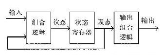
它的实现方案是:现态与输入信号经组合逻辑得到次态,在时钟的上升沿到来时,状态寄存器将次态锁存得到现态,现态经过输出组合逻辑译码得到输出信号。如图 1所示。由于输出必须由现态的状态位经过译码得到,这就需要在现态与输出之间增加一级组合译码逻辑,从而加大了从状态位到器件输出管脚的传输延迟,同样也增加了时钟-输出时延TCO。
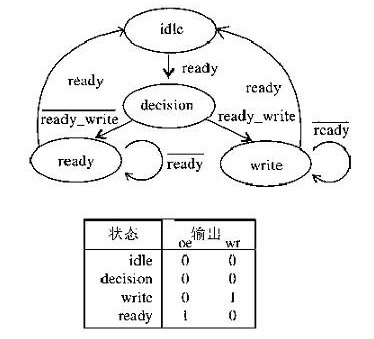
假设一个简单的内存控制器的状态转换图如图2所示。一个完整的读写周期是从空闲状态idle开始。在ready信号有效之后的下一个时钟周期转移到判断状态decision,然后根据read_write信号再转移到read或write状态。则采用这种设计方法的VHDL源程序如下:
signalpresent_state,next_state:std_logic_vector(1 downto 0);
process(clk,ready,read_write,present_state)
begin
if(clk‘eventandclk=’1‘)then
casepresent_stateis
when idle=>oe<=’0‘;wr<=’0‘;
if ready=’1‘ then
next_state<=decision;
else next_state<=idle;
endif;
when decision=>oe<=’0‘;wr<=’0‘;
if(read_write=’1‘)then
next_state<=read;
else next_state<=write;
endif;
when read=>oe<=’1‘;wr<=’0‘;
if(ready=’1‘)then
next_state<=idle;
else next_state<=read;
endif;
when others=>oe<=’0‘;wr<=’1‘;
if(ready=’1‘)then next_state<=idle;
else next_state<=write;
endif;
endcase;endif;
endprocess;
state_clock:process(clk)begin
if(clk’eventandclk=‘1’)then
present_state<=next_state;
endif;
endprocess;
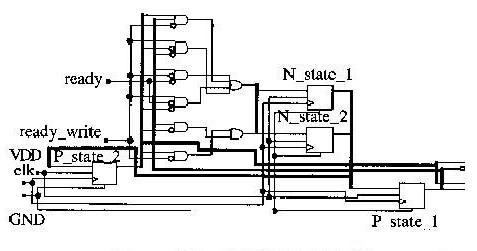
对此程序综合出的电路如图3所示。现态present_state与次态next_state均由两个触发器构成,输出wr和oe均由 present_state经组合译码得到,因此从时钟的上升沿到状态机输出的延迟为通过逻辑阵列的时钟-输出时延TCO2,而不是较短的时钟-输出时延 TCO,且输出信号wr,oe直接来自组合逻辑电路,因而可能有毛刺发生。
2.2 输出由并行输出寄存器译码得到
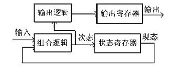
在第一种方法中,主要由于输出组合逻辑引入了延时,从而加大了时钟-输出时延。为了缩短状态机输出到达管脚的延时,可以在锁存状态位之前,先进行输出的组合逻辑译码并将其锁存到专用寄存器中,时钟上升沿到来时,专用寄存器中直接输出wr和oe而没有了组合逻辑引入的延时,从而使状态机输出的延迟为TCO。实现该方案的方框图如图4。采用这种设计方法的VHDL源程序如下:
signalpresent_state:std_logic_vector(1 downto 0);
signalnext_state:std_logic_vector(1 downto 0);
signalwr_d,oe_d:std_logic;
begin
process(clk,ready,read_write)
begin
if(clk‘event and clk=’1‘)then
case present_stateis
when idle=>
if ready=’1‘thennext_state<=decision;
else next_state<=idle;
endif ;
when decision=>
if(read_write=’1‘) then next_state<=read;
else next_state<=write;
endif;
when read=>
if(ready=’1‘)then
next_state<=idle;
else next_state<=read;
endif;
when others=>
if(ready=’1‘)then
next_state<=idle;
else next_state<=write;
endif;
endcase;
endif;
endprocess;
withnext_stateselect
oe_d<=’0‘ whenidle|decision|write,’1‘when others;
withnext_stateselect
wr_d<=’0‘whenidle|decision|read,’1‘when others;
state_clock:process(clk)
begin
if(clk’eventandclk=‘1’)then
present_state<=next_state;
oe<=oe_d;
wr<=wr_d;
endif;
endprocess;
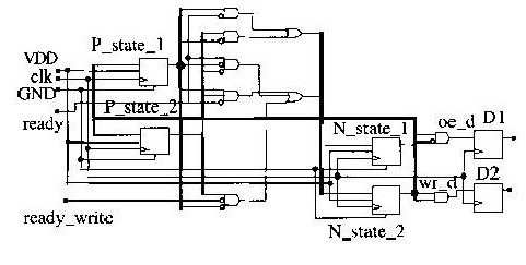
在此程序中,用到了两个新的信号oe_d和wr_d,对次态next_state进行锁存,不象第一种方案中将现态present_state进行译码从而得到在下一个时钟周期oe和wr的取值。对此程序综合出的电路如图5所示。oe_d和wr_d作为锁存器D1和D2的输入。因此D1、D2的输出为上一个次态(即现态)的值。clk的上升沿到来时,D1、D2即将oe_d和wr_d锁存,从而得输出oe和wr。因此从时钟的上升沿到状态机输出的延迟为时钟-输出时延TCO而不是通过逻辑阵列的时钟-输出时延TCO2。又由于时钟信号将输出加载到附加的D触发器中,因而消除了输出信号的毛刺。然而,这种方法存在两个缺点:(1)由于用到了输出寄存器,它比第一种设计需要多用两个寄存器;(2)虽然它的时钟-输出时延从TCO2减小到TCO,但从状态机的状态位到达oe和wr需要经过两级组合逻辑,这就影响了系统时钟的最高频率。
2.3 输出直接从状态位得到
为了能够把时钟-输出时延限制在TCO内,也可以将状态位本身作为输出信号。对于状态位不是很多的状态机而言,这种方法也许较前两种更为优越。某种情况下,可能会出现两种不同状态有相同的状态位,此时只需增加一位状态位加以区别即可。如此程序中,idle、decision、read、write四种状态可分别编码为000,001,100,010。采用这种方法所对应的程序如下:
signalpresent_state:std_logic_vector(2downto0);
state:process(clk,ready,read_write);
begin
if(clk‘eventandclk=’1‘)then
case present_stateis
when “000”=>ifready=’1‘ then present_state<=“001”;
else present_state<=“000”;
endif;
when “001”=>if(read_write=’1‘) then
present_state<=“100”;
else present_state<=“001”;
endif;
when “100”=>if(ready=’1‘)then
present_state<=“000”;
elsepresent_state<=“100”;
endif;
when “010”=>if(ready=’1‘) then present_state<=“000”;
else present_state<=“010”;
endif;
when others=>present_state<=“---”;
endcase;
endif;
endprocess;
oe<=present_state(2);
wr<=present_state(1);
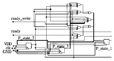
对此程序综合出的电路如图6所示。从图中可知,输出信号未通过额外的逻辑对现态进行译码,而是直接来自状态寄存器,因而输出信号上没有毛刺,并且它所用的宏单元少于通过并行输出寄存器输出的方式。
3 、结论
从以上分析可知,普通MOORE型状态机时延最长,速度最慢,可应用于对速度要求不高的场合。同时,由于它的输出信号中有毛刺,更加限制了它的应用范围。后两种方案在相同的条件下,具有相同的时延,即速度是相同的,但第二 种方案所占用面积要比第三种大得多,且对时钟频率有一定限制。如果可能的话,选择“输出直接从状态位得到”类型状态机是一个理想的方案,因为其速度最快,面积最小,设计这种状态机时,必须在VHDL源码中对状态的编码加以明确的规定,使状态和输出信号的取值一致。所以只有在状态机的规模较小时,才能很好地实现这种类型的设计。
-
有限状态机分割设计2023-10-09 1176
-
一个基于事件驱动的有限状态机2023-08-30 1473
-
如何以面向对象的思想设计有限状态机2022-02-07 638
-
基于事件驱动的有限状态机介绍2021-11-16 2917
-
MOORE型有限状态机的几种设计方法是什么2021-05-07 1929
-
如何使用FPGA实现序列检测有限状态机2020-11-04 1197
-
有限状态机有什么类型?2020-04-06 4191
-
状态机和组合逻辑的冒险竞争浅析2018-06-25 4341
-
初学者对有限状态机(FSM)的设计的认识2017-02-11 4714
-
VHDL有限状态机设计-ST2016-06-08 955
-
有限状态机的建模与优化设计2016-03-22 784
-
有限状态机的硬件描述语言设计方法2010-09-03 753
-
fsm有限状态机pdf2008-06-04 1437
全部0条评论

快来发表一下你的评论吧 !

