
怎么制作显示温度的时钟
电子说
描述
一、。先发下制作完成的成品
手机拍的不是很清楚,但LCD上能看到显示的时间和温度值。
因为国庆忙,还没来加上设置按键和闹钟功能,后续一定补上!见谅!
二、开始制作了
材料清单:
1.万能电路板一块
2.ATmega16单片机一块
3.40DIP插座一块
4.1602LCD液晶显示屏一块
5.ds1820温度传感器一只
6.4.7K电阻一只
7.7.3728Mhz晶振一只
8.27P电容两只
9.排插和排坐若干
10.USB下载线
以上材料淘宝都可以买到,大概40元左右。
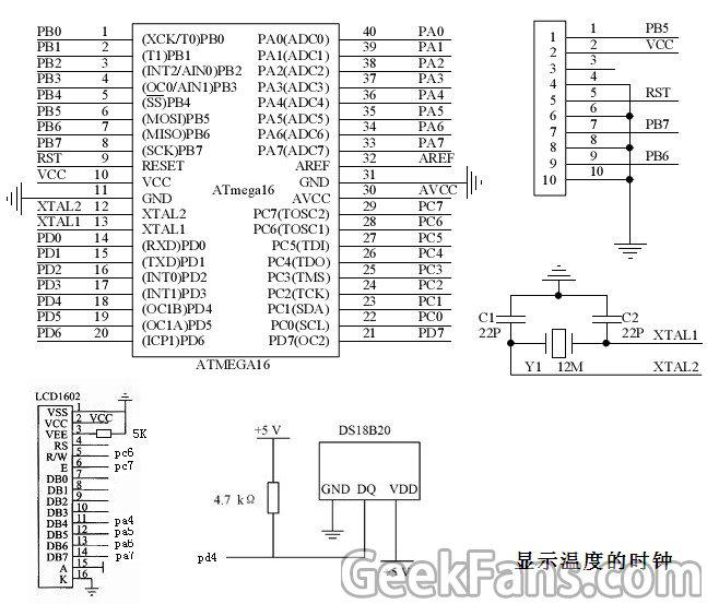
三、我设计的原理图


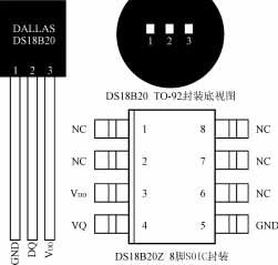
ds1820引脚图(用TO-92封装的)
LCD1602 引脚图
四、按图纸手工焊接,大家动手能力这么强,具体过程我就不写了。
五、程序编写(注:不懂得话可以直接跳过看下面的第六项)
软件使用ICCAVR软件,网上搜下很容易下载。
下面是我写的程序:
#include
#include
#include “delay.h”
#include “1602.h”
unsigned long int j=0;
unsigned int s,t,h;
unsigned char display[9]={0,0,0,0,0,0,0,0,0};//显示数据
typedef unsigned char uint8;/* 定义可移植的无符号8位整数关键字 */
typedef signed char int8;/* 定义可移植的有符号8位整数关键字 */
typedef unsigned int uint16;/* 定义可移植的无符号16位整数关键字 */
typedef signed int int16;/* 定义可移植的有符号16位整数关键字 */
typedef unsigned long uint32;/* 定义可移植的无符号32位整数关键字 */
typedef signed long int32;/* 定义可移植的有符号32位整数关键字 */
extern unsigned char wmh,wml; //全局变量
extern unsigned char count,count1;
#define CLR_DIR_1WIRE DDRD&=~BIT(4) //只要修改这里的参数就可以了!呵呵!
#define SET_DIR_1WIRE DDRD|=BIT(4) //里面什么都不用该!
#define CLR_OP_1WIRE PORTD&=~BIT(4)
#define SET_OP_1WIRE PORTD|=BIT(4)
#define CHECK_IP_1WIRE (PIND & 0x10) //检测 pD4
void init_1820(void);
void write_1820(unsigned char x);
unsigned char read_1820(void);
/*************************************************
** 读取温度值
** 更改全局变量 wmh,wml; 温度的高低位
*************************************************/
extern void gettemp(void);
unsigned char count,count1,flag; //flag温度为负标志,count为实际温度
void init_1820(void)
{
SET_DIR_1WIRE; //设置PC2 为输出
SET_OP_1WIRE;
CLR_OP_1WIRE;
delay_nus(480); //480us以上
SET_OP_1WIRE;
CLR_DIR_1WIRE;
delay_nus(20); //15~60us
while(CHECK_IP_1WIRE);
SET_DIR_1WIRE;
SET_OP_1WIRE;
delay_nus(140); //60~240us
}
void write_1820(unsigned char x)
{
unsigned char m;
for(m=0;m《8;m++)
{
CLR_OP_1WIRE;
if(x&(1《
SET_OP_1WIRE;
else
{CLR_OP_1WIRE;}
delay_nus(40); //15~60us
SET_OP_1WIRE;
}
SET_OP_1WIRE;
}
unsigned char read_1820(void)
{
unsigned char temp,k,n;
temp=0;
for(n=0;n《8;n++)
{
CLR_OP_1WIRE;
SET_OP_1WIRE;
CLR_DIR_1WIRE;
k=(CHECK_IP_1WIRE); //读数据,从低位开始
if(k)
temp|=(1《
else
temp&=~(1《
delay_nus(50); //60~120us
SET_DIR_1WIRE;
}
return (temp);
}
void gettemp(void) //读取温度值
{
unsigned char temh,teml,wm0,wm1,wm2,wm3;
init_1820(); //复位18b20
write_1820(0xcc); // 发出转换命令
write_1820(0x44);
delay_nms(800); //不延时也好使,不知道怎么回事!
init_1820();
write_1820(0xcc); //发出读命令
write_1820(0xbe);
teml=read_1820(); //读数据
temh=read_1820();
wm0=teml》》4; //只要高8位的低四位和低8位的高四位,温度范围0~99啦!
wm1=temh《《4;
j=(temh*256+teml)*5; //计算具体温度
display[1]=j/100%10+0x30;
display[2]=j/10%10+0x30;
display[3]=j%10+0x30;
LCD_write_char(5,1,display[1]);
LCD_write_char(6,1,display[2]);
LCD_write_char(7,1,‘。’);
LCD_write_char(8,1,display[3]);
LCD_write_char(9,1,‘C’);
}
//TIMER1 initialize - prescale:1024
// WGM: 0) Normal, TOP=0xFFFF
// desired value: 1Sec
// actual value: 1.000Sec (0.0%)
void timer1_init(void)
{
TCCR1B = 0x00; //stop
TCNT1H = 0xE3; //setup
TCNT1L = 0xE1;
OCR1AH = 0x1C;
OCR1AL = 0x1F;
OCR1BH = 0x1C;
OCR1BL = 0x1F;
ICR1H = 0x1C;
ICR1L = 0x1F;
TCCR1A = 0x00;
TCCR1B = 0x05; //start Timer
}
void init_devices(void)
{
//stop errant interrupts until set up
CLI(); //disable all interrupts
timer1_init();
MCUCR = 0x00;
GICR = 0x00;
TIMSK = 0x1C; //timer interrupt sources
SEI(); //re-enable interrupts
//all peripherals are now initialized
}
#pragma interrupt_handler timer1_ovf_isr:9
void timer1_ovf_isr(void)
{
//TIMER1 has overflowed
TCNT1H = 0xE3; //reload counter high value
TCNT1L = 0xE1; //reload counter low value
if(s++ == 59)
{s=0;
if(t++ == 59)
{t=0;
if(h++ == 24)
{h=1;
}
}
}
}
void dis(void)
{
display[4]=s/10+0x30;
display[5]=s%10+0x30;
display[6]=t/10+0x30;
display[7]=t%10+0x30;
display[8]=h/10+0x30;
display[9]=h%10+0x30;
LCD_write_char(10,0,display[5]);
LCD_write_char(9,0,display[4]);
LCD_write_char(8,0,‘:’);
LCD_write_char(7,0,display[7]);
LCD_write_char(6,0,display[6]);
LCD_write_char(5,0,‘:’);
LCD_write_char(4,0,display[9]);
LCD_write_char(3,0,display[8]);
delay_nms(50);
}
void main(void)
{h=24;
t=59;
s=55;
init_devices();
LCD_init();
delay_nms(50);
while(1)
{
gettemp();
dis();
delay_nms(500);
}
}
经过ICCAVR编译后生成的 hex 就是我们下载到单片机需要的文件。
六。下载 time.hex 到单片机
1.先下载 time.hex 文件
2.把USB下载线插在ISP接口上。
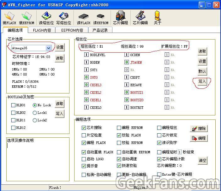
3.运行 AVR_fighter 软件(买USB下载线送的配套软件)

按图红圈先选择 ATMEGA16,再设置好熔丝位,最后点击写入。
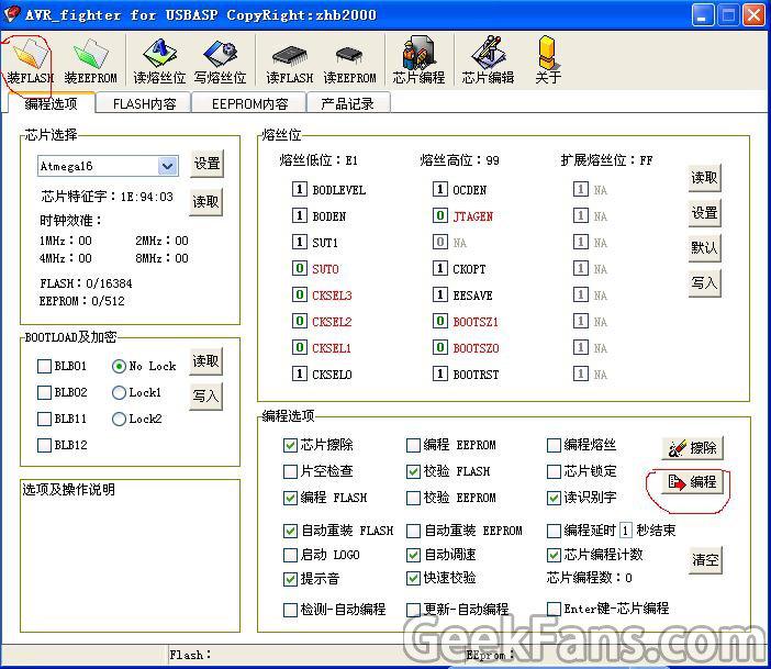
4.

点击 装FLASH 按钮选择 time.hex 文件后,点击 编程。
几秒后你就会看到液晶显示出时间和温度值,因为因为国庆忙,还没来加上设置按键和闹钟功能,后续加下,见谅!
不过聪明的你一定看出来了,只要提前设定好 s,t,h(时、分、秒)编译后下载,时钟就能按你的要求工作了。
-
以VB程序显示的温度传感器制作2009-11-20 724
-
制作液晶显示温度计的方法2010-03-09 3492
-
基于51单片机的时钟+温控系统的小制作2015-11-17 1014
-
带日历时钟及温度显示的电子万年历2015-12-07 3461
-
基于单片机的彩屏模块(1.8寸彩屏程序-1)温度-时钟综合显示2016-01-06 709
-
基于单片机的彩屏模块(1.8寸彩屏程序-2)温度-时钟综合显示2016-01-12 615
-
单片机数字时钟温度计闹钟计算器制作2016-09-12 559
-
DS1302时钟电子表闹钟 旋转LED显示 创意时钟DIY 温度显示报警设计2018-01-12 1367
-
如何制作一个多功能便携时钟?2018-08-10 5650
-
Arduino天气时钟的制作教程2019-08-01 8368
-
如何制作一个带有温度和湿度显示的木质时钟2019-08-23 4277
-
基于51单片机1602温度显示时钟2021-11-05 640
-
RTX51tiny 复杂应用---时钟、温度显示、按键解析2021-11-21 471
-
使用实时时钟IC DS1307制作精确时钟的方法2022-04-26 6633
-
基于51单片机时钟温度显示设计2024-06-25 208
全部0条评论

快来发表一下你的评论吧 !

