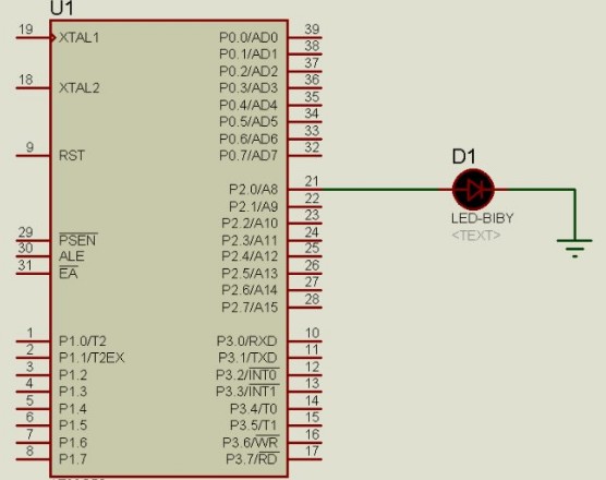

PIC单片机如何实现单按键输入LED灯点亮
控制/MCU
描述
IO输出和输入
/*
按键连接RB1,点亮LED,PORTA RA0控制输出。按一次点亮,再按一次熄灭,如此循环。
RB外接上拉电阻。

*/
#include
#define uchar unsigned char
#define uint unsigned int
// CONFIG
#pragma config FOSC = HS //
#pragma config WDTE = OFF // Watchdog Timer Enable bit (WDT disabled)
#pragma config PWRTE = OFF // Power-up Timer Enable bit (PWRT disabled)
#pragma config BOREN = ON // Brown-out Reset Enable bit (BOR enabled)
#pragma config LVP = ON // Low-Voltage (Single-Supply) In-Circuit Serial Programming Enable bit (RB3/PGM pin has PGM function; low-voltage programming enabled)
#pragma config CPD = OFF // Data EEPROM Memory Code Protection bit (Data EEPROM code protection off)
#pragma config WRT = OFF // Flash Program Memory Write Enable bits (Write protection off; all program memory may be written to by EECON control)
#pragma config CP = OFF // Flash Program Memory Code Protection bit (Code protection off)
uchar count;
void delay(uint x)
{
uint y,z;
for(y=x;y》0;y--)
for(z=25;z》0;z--);
}
void Init_GPIO()
{
TRISA = 0X00; // RA0 output direction
PORTA=0X00;
TRISB = 0x02; // RB1 input
PORTB = 0x00;
}
void Keyscan()
{
//temp = PORTB&0x02;
if(RB1==0)
{
delay(200); // delay time 根据机械按键的抖动情况调整,
if(RB1==0)
{
count++;
}
}
}
void main(void)
{
count = 0;
Init_GPIO();
while(1)
{
Keyscan();
if((count%2)==1)
{
PORTA=0x01;
}
else
PORTA = 0x00;
}
}
-
C51单片机实现独立按键点亮LED灯2021-12-13 0
-
怎么实现51单片机led灯依次点亮?2021-10-14 0
-
如何利用51单片机实现led灯的点亮?2021-10-26 0
-
单片机实现独立按键控制Led灯2022-01-06 0
-
如何利用C51单片机去实现一种独立按键点亮LED灯的设计呢2022-01-24 0
-
使用51单片机实现LED灯点亮和独立按键扫描及数码管动态显示的概述2019-08-27 1920
-
如何使用单片机点亮LED灯2019-07-16 2240
-
使用单片机实现点亮一个LED灯的程序和仿真资料免费下载2021-03-18 952
-
51单片机——LED灯的点亮2021-11-11 1367
-
PIC单片机 按键检测识别2021-11-16 628
-
51单片机——点亮一个LED灯2021-11-23 2514
-
基于单片机点亮LED灯2023-05-24 1848
-
单片机入门之点亮LED灯2023-06-26 2663
-
基于51单片机点亮LED灯2023-07-11 1799
-
单片机独立按键控制led灯程序2023-09-02 4620
全部0条评论

快来发表一下你的评论吧 !

