

详解 TI AWR1642汽车短距离雷达(SRR)参考设计
汽车电子
描述
TI公司的AWR1642是工作在76-81GHz频段的单片FMCW雷达传感器,采用低功耗的45nm的RFCMOS工艺,具有调频连续波(FMCW)收发器,集成了整数PLL,发送器,接收器,基带和A2D,有四个接收通路,2个发送通路,发送功率12.5dBm,76 - 77 GHz时的接收噪音14dB,77-81 GHz时的接收噪音15dB,采用基于ARM® Cortex®-R4F的无线电控制系统,具有内置的校验和自测,主要用在盲点检测,变道辅助,停车辅助,路口交通警报,占用检测,简单手势识别和车门开启应用.本文介绍了AWR1642主要特性,框图和应用电路与参考电路图,评估模块AWR1642BOOST主要特性以及采用评估模块的短距离雷达(SRR)参考设计TIDEP-0092主要特性和指标,框图,电路图和材料清单.
The AWR1642 device is an integrated single-chip FMCW radar sensor capable of operation in the 76- to81-GHz band. The device is built with TI’s low-power 45-nm RFCMOS process and enablesunprecedented levels of integration in an extremely small form factor. The AWR1642 is an ideal solutionfor low-power, self-monitored, ultra-accurate radar systems in the automotive space.
The AWR1642 device is a self-contained FMCW radar sensor single-chip solution that simplifies theimplementation of Automotive Radar sensors in the band of 76 to 81 GHz. It is built on TI’s low-power 45-nm RFCMOS process, which enables a monolithic implementation of a 2TX, 4RX system with built-in PLLand A2D converters. It integrates the DSP subsystem, which contains TI’s high-performance C674x DSPfor the Radar Signal processing. The device includes an ARM R4F-based processor subsystem, which isresponsible for radio configuration, control, and calibration. Simple programming model changes canenable a wide variety of sensor implementation (Short, Mid, Long) with the possibility of dynamicreconfiguration for implementing a multimode sensor. Additionally, the device is provided as a completeplatform solution including reference hardware design, software drivers, sample configurations, API guide,and user documentation.
AWR1642主要特性:
• FMCW Transceiver
– Integrated PLL, Transmitter, Receiver,Baseband, and A2D
– 76- to 81-GHz Coverage With 4 GHz AvailableBandwidth
– Four Receive Channels
– Two Transmit Channels
– Ultra-Accurate Chirp (Timing) Engine Based onFractional-N PLL
– TX Power: 12.5 dBm
– RX Noise Figure:
– 14 dB (76 to 77 GHz)
– 15 dB (77 to 81 GHz)
– Phase Noise at 1 MHz:
– –95 dBc/Hz (76 to 77 GHz)
– –93 dBc/Hz (77 to 81 GHz)
• Built-in Calibration and Self-Test (Monitoring)
– ARM® Cortex®-R4F-Based Radio ControlSystem
– Built-in Firmware (ROM)
– Self-calibrating System Across Frequency andTemperature
• C674x DSP for FMCW Signal Processing
• On-Chip Memory: 1.5MB
• Cortex-R4F Microcontroller for Object Tracking and
Classification, AUTOSAR, and Interface Control
– Supports Autonomous Mode (Loading UserApplication from QSPI Flash Memory)
• Integrated Peripherals
– Internal Memories With ECC
• Host Interface
– CAN (Two Instances, One Being CAN-FD)
• Other Interfaces Available to User Application
– Up to 6 ADC Channels
– Up to 2 SPI Channels
– Up to 2 UARTs
– I2C
– GPIOs
– 2-Lane LVDS Interface for Raw ADC Data andDebug Instrumentation
• ASIL B Targeted
• AECQ100 Qualified
• AWR1642 Advanced Features
– Embedded Self-monitoring With No HostProcessor Involvement
– Complex Baseband Architecture
– Embedded Interference Detection Capability
• Power Management
– Built-in LDO Network for Enhanced PSRR
– I/Os Support Dual Voltage 3.3 V/1.8 V
• Clock Source
– Supports External Oscillator at 40 MHz
– Supports Externally Driven Clock (Square/Sine)at 40 MHz
– Supports 40 MHz Crystal Connection with LoadCapacitors
• Easy Hardware Design
– 0.65-mm Pitch, 161-Pin 10.4 mm × 10.4 mmFlip Chip BGA Package for Easy Assembly andLow-Cost PCB Design
– Small Solution Size
• Supports Automotive Temperature OperatingRange
AWR1642应用:
• Blind Spot Detection
• Lane Change Assistance
• Cross Traffic Alert
• Parking Assistance
• Occupancy Detection
• Simple Gesture Recognition
• Car Door Opener Applications
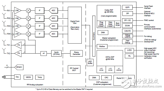
图1.AWR1642功能框图
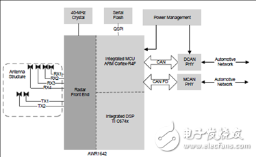
图2.AWR1642自主雷达传感器汽车应用框图
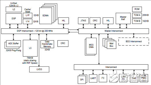
图3.处理器子系统框图
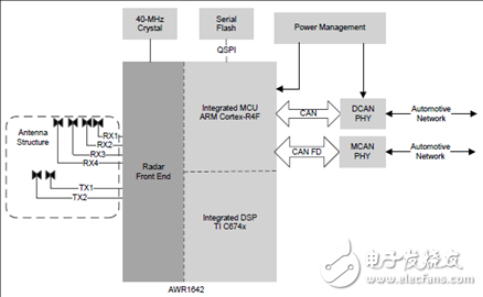
图4.短距离雷达框图
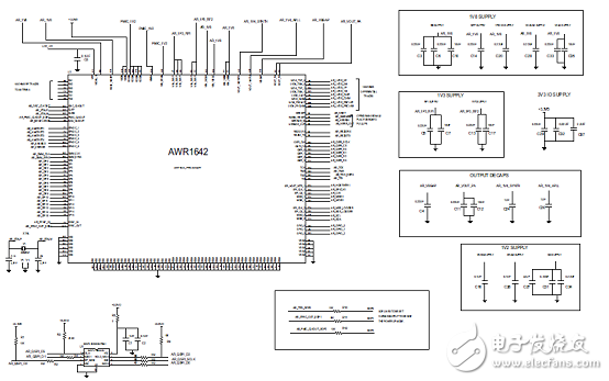
图5.AWR1642参考电路图
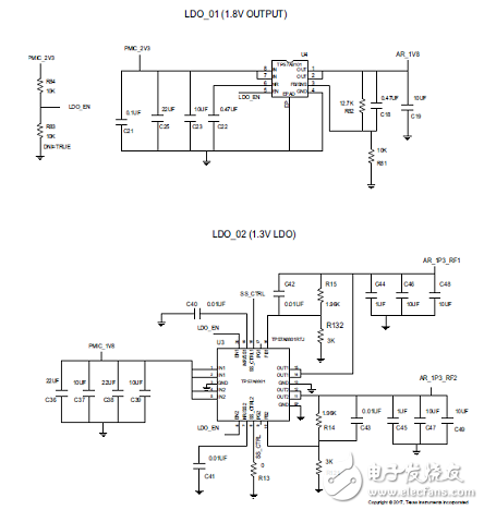
图6.AWR1642低噪音LDO电路图
图7.AWR1642参考电路PCB设计图(顶层走线)
图8.AWR1642参考电路PCB设计图(顶层走线Closeup)
图9.AWR1642参考电路PCB设计图(底层走线)
AWR1642评估模块(AWR1642BOOST)单片mmWave检测解决方案
The AWR1642 BoosterPack from Texas Instruments is an easy-to-use evaluation board for the AWR1642mmWave sensing device, with direct connectivity to the microcontroller (MCU) LaunchPad DevelopmentKit. The BoosterPack contains everything required to start developing software for on-chip C67x DSP coreand low-power ARM R4F controllers, including onboard emulation for programming and debugging as wellas onboard buttons and LEDs for quick integration of a simple user interface.
The standard 20-pin BoosterPack headers make the device compatible with a wide variety of TI MCULaunchPads and enables easy prototyping.
评估模块AWR1642BOOST主要特性:
• Two 20-pin LaundPad connectors that leverages the ecosystem of the TI LaunchPad
• XDS110 based JTAG emulation with a serial port for onboard QSPI flash programming
• Back-channel UART through USB-to-PC for logging purposes
• Onboard antenna
• 60-pin, high-density (HD) connector for raw analog-to-digital converter (ADC) data over LVDS andtrace-data capability
• Onboard CAN-FD transceiver
• One button and two LEDs for basic user interface
• 5-V power jack to power the board
评估模块AWR1642BOOST包括:
• AWR1642BOOST evaluation board
• Mounting brackets, screws, and nuts to place the printed-circuit board (PCB) vertical
• Micro USB cable to connect to PC
图10.评估模块AWR1642BOOST外形图(正面)
图11.评估模块AWR1642BOOST外形图(背面)
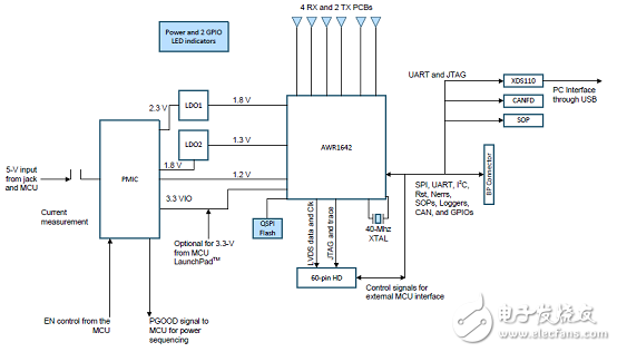
图12.评估模块AWR1642BOOST框图
采用评估模块AWR1642BOOST的短距离雷达(SRR)参考设计TIDEP-0092
The TIDEP-0092 provides a foundation for a shortrange radar (SRR) application using the AWR1642evaluation module (EVM). This design allows the userto estimate and track the position (in the azimuthalplane) and the velocity of objects in its field of view up to 80 m.
Autonomous control of a vehicle provides quality-of-life and safety benefits in addition to making therelatively mundane act of driving safer and less difficult. The quality-of-life features include the ability of avehicle to park itself or to determine whether a lane change is possible and provide features like automaticcruise control—where a vehicle maintains a constant distance with respect to the car ahead of it,essentially tracking the velocity of the car in front of it. Autonomous breaking and collision avoidance aresafety features that prevent accidents caused by driver inattention. These features work by observing thearea in front of a car and alerting the autonomous driving subsystems if obstacles are observed that arelikely to hit the car. Implementing these technologies require a variety of sensors to detect obstacles in theenvironment and track their velocities and positions over time.
参考设计TIDEP-0092主要特性:
• Single-Chip FMCW Radio Detection and Ranging(RADAR) for SRR Applications
• Detect Objects (Such as Cars and Trucks) up to80-m Away With Range Resolution of 35 cm;Objects 20-m Away Detectable With Resolution of4.3 cm
• Clustering and Tracking on Detected Outputs
• Antenna Field of View ±60º With AngularResolution of Approximately 15º
• Source Code for Fast Fourier Transform (FFT)Processing and Detection Provided by mmWaveSoftware Development Kit (SDK)
• AWR1642 Demonstrates Design
• Radar Front End and Detection Configuration FullyExplained
参考设计TIDEP-0092应用:
• Lane Change Assist (LCA)
• Autonomous Parking
• Cross Traffic Alert (CTA)
• Blind Spot Detection (BSD)
图13.参考设计TIDEP-0092外形图
参考设计TIDEP-0092主要系统指标:
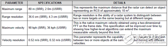
图14.SRR系统框图
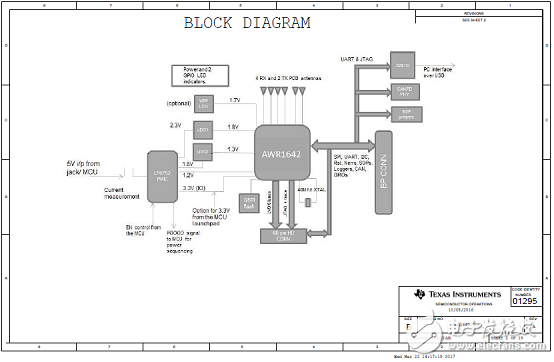
图15.参考设计TIDEP-0092电路图(1)
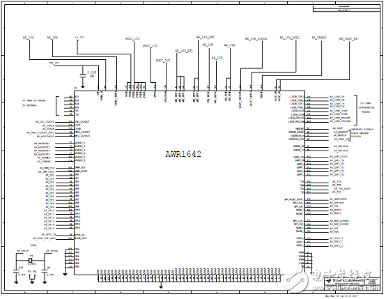
图16.参考设计TIDEP-0092电路图(2)
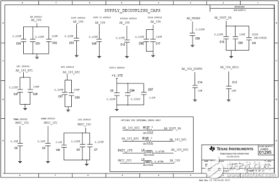
图17.参考设计TIDEP-0092电路图(3)
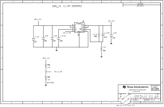
图18.参考设计TIDEP-0092电路图(4)
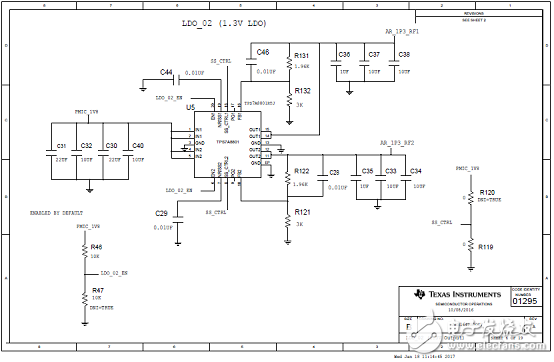
图19.参考设计TIDEP-0092电路图(5)
图20.参考设计TIDEP-0092电路图(6)
图21.参考设计TIDEP-0092电路图(7)
图22.参考设计TIDEP-0092电路图(8)
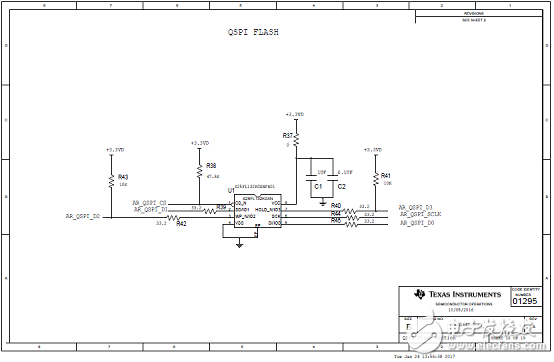
图23.参考设计TIDEP-0092电路图(9)
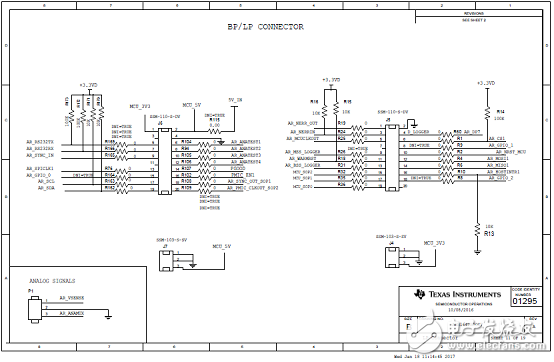
图24.参考设计TIDEP-0092电路图(10)
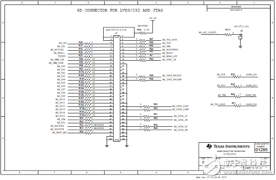
图25.参考设计TIDEP-0092电路图(11)
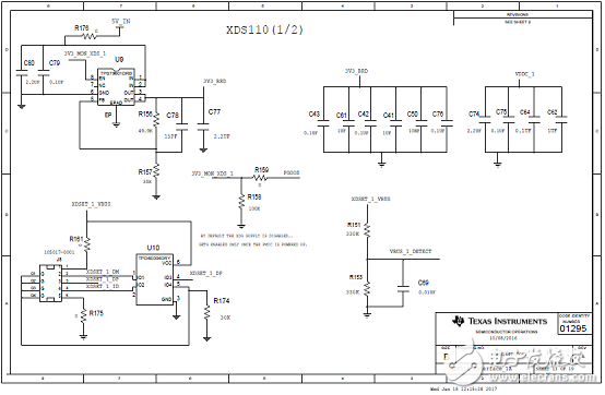
图26.参考设计TIDEP-0092电路图(12)
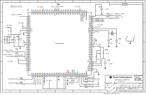
图27.参考设计TIDEP-0092电路图(13)
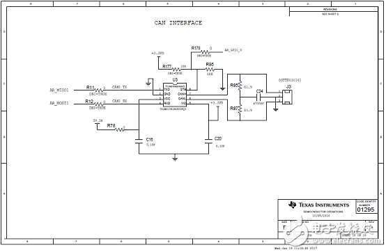
图28.参考设计TIDEP-0092电路图(14)
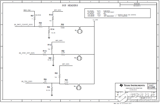
图29.参考设计TIDEP-0092电路图(15)
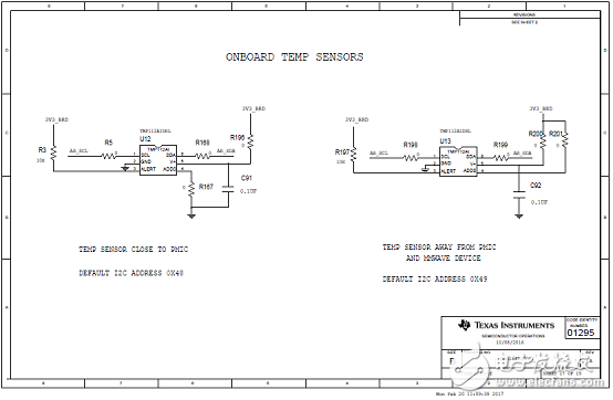
图30.参考设计TIDEP-0092电路图(16)
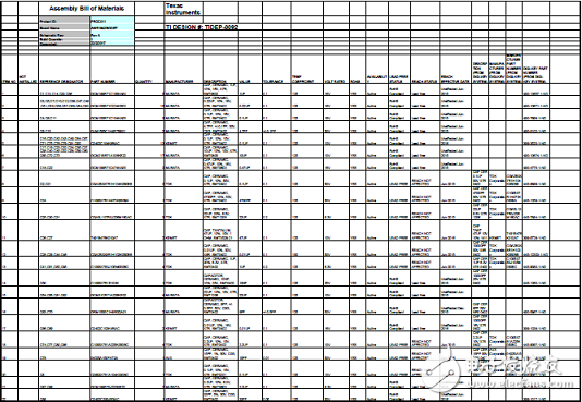
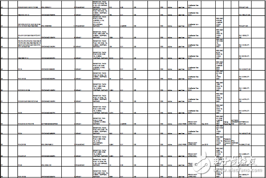
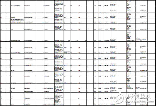
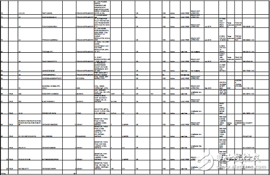
参考设计TIDEP-0092材料清单:

详情请见:
和
以及
和
与
swrs203a.pdf
swru508b.pdf
tidud36b.pdf
tidrqr9.pdf
-
AWR1642:77/79GHz FMCW雷达传感器的卓越之选2026-02-12 744
-
实现IWR1642/AWR1642 GPADC的功能2022-11-11 666
-
基于AWR1642的短程雷达解决方案2022-11-07 1015
-
在IWR1642/AWR1642上修改L3 RAM的分布2022-11-01 687
-
TI AWR1642 学习笔记4之串口数据流解析 精选资料分享2021-07-27 1980
-
短距离雷达 (SRR) 参考设计2019-01-25 5321
-
使用AWR1642评估模块的短距离雷达参考设计2018-10-23 3640
-
基于TI产品的短距离雷达参考设计2018-09-25 1609
-
请问毫米波雷达AWR1642 CAN功能如何使用?2018-08-19 3284
-
开源硬件-TIDEP-0092-短距离雷达 (SRR) PCB layout 设计2017-12-11 572
-
使用AWR1642短程雷达参考设计2017-05-26 4691
全部0条评论

快来发表一下你的评论吧 !
