

TPS65987D应用电路以及200W USB-C PD参考设计
电子说
描述
TI公司的TPS65987D是单独可用的集成了功率开关的USB Type-C和供电(PD)控制器,和USB PD 3.0兼容,提供电缆插头和取向检测,根据电缆检测,采用USB PD协议和CC线进行通信,当电缆检测和USB PD协商完成, TPS65987D就能提供合适供电通路,配置交替模式来设定外部多路复用器。主要用在笔记本电脑,坞站系统,平板电脑和超级本电脑, DisplayPort与雷电接口系统。本文介绍了TPS65987D主要特性,功能框图,应用电路, 评估模块10-GEXPANSION-EVM主要特性,电路图,材料清单和PCB设计图以及200W USB-C PD参考设计TIDA-050012主要特性和指标,框图,材料清单和PCB设计图。
The TPS65987D is a stand-alone USB Type-C and Power Delivery (PD) controller providing cable plug and orientation detection for a single USB Type-C connector. Upon cable detection, the TPS65987D communicates on the CC wire using the USB PD protocol. When cable detection and USB PD negotiation are complete, the TPS65987D enables the appropriate power path and configures alternate mode settings for external multiplexers.
TPS65987D主要特性:
1• USB Power Delivery (PD) Controller
– USB PD 3.0 Compliant
– Fast Role Swap Support
– Physical Layer and Policy Engine
– Configurable at Boot and Host-Controlled
• USB Type-C Specification Compliant
– Cable Attach and Orientation Detection
– Default, 1.5 A, or 3 A Power Advertisement
– Up to 600-mA VConn Current
• Port Power Switch
– Two 5 V to 20 V, 5-A Bidirectional Switches to or from VBUS
– Up to 10-A Adjustable Current Limiting
– Ideal Diode Reverse Current Protection
– Undervoltage, and Overvoltage Protection
– Slew Rate Control
– 5-V, 600-mA VConn Source
• BC1.2 Support
– Advertisement as DCP and CDP
– Automatic DCP Modes Selection:
– Shorted Mode per BC1.2 and YD/T 1591-2009
– 2.7-V Divider 3 Mode
– 1.2-V Mode
– Data Contact Detect
– Primary and Secondary Detection
• I2C Master Write Control for Alt Mode Muxes and Variable DCDCs
• Alternate Mode Support
– DisplayPort
– Thunderbolt™
• Power Management
– Power Supply from 3.3 V or VBUS Source
– 3.3-V LDO Output for Dead Battery Support
• 7-mm × 7-mm QFN Package
– 0.4-mm Pitch
– 56 Pin
TPS65987D应用:
• Notebook Computers
• Docking Systems
• Tablets and Ultrabooks
• DisplayPort, and Thunderbolt™ Systems

图1. TPS65987D功能框图

图2. TPS65987D简化电路图

图3.端口电源开关

图4.数字核框图

图5. TPS65987D应用案例电路图

图6. TPS65987D应用案例2电路图

图7. TPS65987D支持PD充电的USB和DisplayPort笔记本电路图

图8. TPS65987D支持PD充电的雷电数据线笔记本电路图
评估模块10-GEXPANSION-EVM
This is the user’s guide for the 10G-EXPANSION-EVM for use with the TPS65987EVM supporting the expansion board connector. The 10G-EXPANSION-EVM is not intended to be used alone and requires the TPS65987EVM for operation.
The 10G-EXPANSION-EVM adds to the capabilities of the TPS6598xEVM supporting the expansion board connector by allowing the user to evaluate the USB Type-C and power-delivery (PD) capabilities of the TPS6598x USB Type-C and PD devices from the power and data perspective.
The TPS6598x USB Type-C and PD controller provides cable plug and orientation detection at the USB Type-C connector. Upon cable detection, the TPS6598x device communicates on the CC wire using the USB PD protocol. When cable detection and USB PD negotiation are complete, the TPS6598x device enables the appropriate power path and configures alternate mode settings for internal and (optional) external multiplexers.
This user guide describes the TPS65987EVM and the capabilities of this EVM with the 10GEXPANSIONEVM.
图9. 评估模块10-GEXPANSION-EVM外形图

图10. 评估模块10-GEXPANSION-EVM源板和沉板框图

图11. 评估模块10-GEXPANSION-EVM沉板MUX电路图

图12. 评估模块10-GEXPANSION-EVM内PCB沉电路图
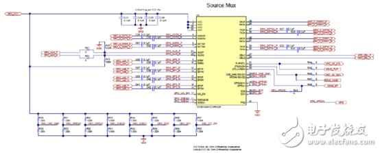
图13. 评估模块10-GEXPANSION-EVM源MUX电路图

图14. 评估模块10-GEXPANSION-EVM内PCB源电路图
评估模块10-GEXPANSION-EVM材料清单:


图15. 评估模块10-GEXPANSION-EVM PCB设计图:左:顶层综合;右:顶层焊接

图16. 评估模块10-GEXPANSION-EVM PCB设计图:左:顶层;右:GND面1

图17. 评估模块10-GEXPANSION-EVM PCB设计图:左:高速层;右:GND面2

图18. 评估模块10-GEXPANSION-EVM PCB设计图:左:电源层1;右:电源层2

图19. 评估模块10-GEXPANSION-EVM PCB设计图:左:GND面3;右:底层

图20. 评估模块10-GEXPANSION-EVM PCB设计图:左:底层焊接;右:底层综合
电源UDO源200W USB-C PD参考设计TIDA-050012
This USB Power Delivery (PD) reference design will allow users to implement system that require more than 100 W as a power source while also highlighting the industries lowest RDSon solution. The design can output all four of the standard USB Type-C PD source
voltages of 5 V, 9 V, 15 V, and 20 V. In standard Type-C PD operation, the design will output up to 20V/4A. When Texas Instruments Power DUO mode is enabled, the design will be able to output up to 20V/10A while simultaneously lowering the RDSon by a factor of two.
This Design highlights how to implement a high powered USB Type-C PD Source device. This design can be referenced for various different end equipments, from PC Docks, Notebook PC Charger, Industrial chargers, Wall outlets, and many others. Through the use of a Texas Instruments USB Power Duo Mode, the TPS65987D PD adapter will close both of it's load switches in parallel to double the current carrying capability and reduce the effective RDSon by a factor of two. The design also highlights a feature of the TPS65987D called App Config by allowing users to select their Type-C PD Output voltage through push button switches. Additionally, this design goes through steps on how to implement a high powered DC/DC converter to offer the standard Type-C PD source voltages. Finally, the design also contains a P-FET bypass power path to route the input supply directly to the PD controller allowing for very high efficiency in a 20 V contract. The design also supports BC1.2 charging modes through the D+/D- USB 2.0 signals.
参考设计TIDA-050012主要特性:
• High Power USB Type-C PD Source
• Barrel Jack to Type-C: 5-V, 9-V, 15-V, or 20-V Charging up to 4 A
• Up to 20-V at 10 A through Texas Instruments Power Duo Mode
• Integrated power paths in PD Controller
• User selectable output voltage
参考设计TIDA-050012应用:
• Notebooks and Laptops
• Personal Electronics
• Consumer AC/DC: USB Type-C AC/DC Notebook PC Power Adapters (60 W Minimum)
• Power Bank
• Notebook PC Power Adapters
图21. 参考设计TIDA-050012外形图

图22. 参考设计TIDA-050012框图
参考设计TIDA-050012主要指标:
参考设计TIDA-050012材料清单:


图23. 参考设计TIDA-050012 PCB设计图(1)

图24. 参考设计TIDA-050012 PCB设计图(2)

图25. 参考设计TIDA-050012 PCB设计图(3)

图26. 参考设计TIDA-050012 PCB设计图(4)

图27. 参考设计TIDA-050012 PCB设计图(5)

图28. 参考设计TIDA-050012 PCB设计图(6)

图29. 参考设计TIDA-050012 PCB设计图(7)

图30. 参考设计TIDA-050012 PCB设计图(8)
- 相关推荐
- 热点推荐
- u
-
Texas Instruments TPS65987DDKEVM 评估模块(EVM)数据手册2025-07-23 437
-
USB PD 3.0控制器TPS65987DDK浪涌防护方案2025-04-10 671
-
USB PD 3.0控制器TPS65987DDJ浪涌防护方案2025-04-08 720
-
TPS65988和TPS65987D PD3.0快速角色互换2024-09-29 489
-
TPS65987D和TPS65988 BC1.2实施指南2024-09-25 516
-
TPS65987D GPIO事件2024-09-23 369
-
支持USB3和交替模式的USB Type-C® 和USB PD控制器TPS65987D数据表2024-03-05 413
-
开源硬件-TIDA-050014-Power DUO 灌电流 200W USB-C PD PCB layout 设计2020-10-22 1073
-
TI TPS65987DUSB Type-C和PD控制器解决方案2019-04-17 6543
-
TPS65987D TPS65987D2018-10-16 1271
-
200W功率的灯闪光电路,200W Lamp Flasher2010-02-27 3408
-
200W音频放大器电路--200W Audio Amplif2009-12-26 2154
全部0条评论

快来发表一下你的评论吧 !
