

TDA3x系列多传感器平台ADAS参考设计
传感器
描述
TI公司的TDA3x系列是高度优化和可升级系统级芯片(SoC),满足一流的先进驾驶辅助系统要求,具有图像和视频加速功能,使性能,低功耗,小型尺寸和ADAS可视分析处理优化,便利实现更加自主的和无碰撞驾驭体验。视频和图像处理支持全高清视频(1920×1080p,60fps),视频输入和视频输出,具有高达2个C66x浮点VLIW DSP,目标代码完全和C67x与C64x+兼容,每周期有多达32个16x16位定点乘法,主要应用在单声道,立体声或三光前置摄像头,LVDS或以太网环绕观测,以及传感器融合如可视,雷达,超声波和激光雷达传感器。本文介绍了TDA3x系列主要特性,框图,以及多传感器平台ADAS参考设计TIDEP-01008主要特性,框图,电路图,材料清单和PCB设计图。
TI’s TDA3x System-on-Chip (SoC) is a highly optimized and scalable family of devices designed to meetthe requirements of leading Advanced Driver Assistance Systems (ADAS)。 The TDA3x family enablesbroad ADAS applications in automobiles by integrating an optimal mix of performance, low power, smallerform factor and ADAS vision analytics processing that aims to facilitate a more autonomous and collisionfree
driving experience.
The TDA3x SoC enables sophisticated embedded vision technology in today’s automobile by enabling theindustry’s broadest range of ADAS applications including front camera, rear camera, surround view, radar,and fusion on a single architecture.
The TDA3x SoC incorporates a heterogeneous, scalable architecture that includes a mix of TI’s fixed andfloating-point TMS320C66x digital signal processor (DSP) generation cores, Vision AccelerationPac(EVE), and dual-Cortex-M4 processors. The device allows low power profile in different package options(including Package-On-Package) to enable small form factor designs. TDA3x SoC also integrates a hostof peripherals including multi-camera interfaces (both parallel and serial) for LVDS-based surround viewsystems, displays, CAN and GigB Ethernet AVB.
The Vision AccelerationPac for this family of products includes embedded vision engine (EVE) offloadingthe vision analytics functionality from the application processor while also reducing the power footprint.
The Vision AccelerationPac is optimized for vision processing with a 32-bit RISC core for efficient programexecution and a vector coprocessor for specialized vision processing.Additionally, Texas Instruments provides a complete set of development tools for the Arm, DSP, and EVEcoprocessor, including C compilers, a DSP assembly optimizer to simplify programming and scheduling,and a debugging interface for visibility into source code execution.The TDA3x ADAS processor is qualified according to AEC-Q100 standard.
TDA3x系列主要特性:
• Architecture Designed for ADAS Applications
• Video and Image Processing Support
– Full-HD Video (1920 × 1080p, 60 fps)
– Video Input and Video Output
• Up to 2 C66x Floating-Point VLIW DSP
– Fully Object-Code Compatible With C67x andC64x+
– Up to Thirty-two 16 × 16-Bit Fixed-PointMultiplies per Cycle
• Up to 512kB of On-Chip L3 RAM
• Level 3 (L3) and Level 4 (L4) Interconnects
• Memory Interface (EMIF) Module
– Supports DDR3/DDR3L up to DDR-1066
– Supports DDR2 up to DDR-800
– Supports LPDDR2 up to DDR-667
– Up to 2GB Supported
• Dual Arm® Cortex®-M4 Image Processor (IPU)
• Vision AccelerationPac
– Embedded Vision Engine (EVE)
• Display Subsystem
– Display Controller With DMA Engine
– CVIDEO / SD-DAC TV Analog CompositeOutput
• Video Input Port (VIP) Module
– Support for up to 4 Multiplexed Input Ports
• On-chip Temperature Sensor That is Capable ofGenerating Temperature Alerts
• General-Purpose Memory Controller (GPMC)
• Enhanced Direct Memory Access (EDMA)Controller
• 3-Port (2 External) Gigabit Ethernet (GMAC)Switch
• Controller Area Network (DCAN) Module
– CAN 2.0B Protocol
• Modular Controller Area Network (MCAN) Module
– CAN 2.0B Protocol
• Eight 32-Bit General-Purpose Timers
• Three Configurable UART Modules
• Four Multichannel Serial Peripheral Interfaces(McSPI)
• Quad SPI Interface
• Two Inter-Integrated Circuit (I2C) Ports
• Three Multichannel Audio Serial Port (McASP)Modules
• MultiMedia Card/Secure Digital/Secure DigitalInput Output Interface (MMC™/ SD™/SDIO)
• Up to 126 General-Purpose I/O (GPIO) Pins
• Power, Reset, and Clock Management
• On-Chip Debug With CTools Technology
• Automotive AEC-Q100 Qualified
• 15×15mm, 0.65-mm Pitch, 367-Pin PBGA (ABF)
• Seven Dual Clock Comparators (DCC)
• Memory Cyclic Redundancy Check (CRC)
• TESOC (LBIST/PBIST) That Enables Field Testingof Logic and On-Chip Memory
• Error Signaling Module (ESM)
• Five Instances of Real-Time Interrupt (RTI)Modules That Can be Used as Watch Dog Timers
• 8-Channel 10-bit ADC
• MIPI® CSI-2 Camera Serial Interface
• PWMSS
• Full HW Image Pipe: DPC, CFA, 3D-NF, RGBYUV
– WDR, HW LDC and Perspective
TDA3x系列应用:
• Mono, Stereo or Tri-Optic Front Camera
– Object Detection
– Pedestrian Detection
– Traffic Sign Recognition
– Lane Detection and Departure Warning
– Automatic Emergency Braking
– Adaptive Cruise Control
– Forward Collision Warning
– High Beam Assist
• LVDS or Ethernet Surround View
– 2D surround view
– 3D surround view
– Rear object detection
– Parking assist
– Pedestrian Detection
– Lane tracking
– Drive Recording
• Sensor Fusion – Vision, Radar, Ultrasonic, Lidarsensors
– Object data fusion
– Raw data fusion

图1.TDA3x系列框图
多传感器平台参考设计
The Multi-Sensor Platform Reference Design for TexasInstruments™ Jacinto™ TDA3x Advanced DriverAssistance Systems (ADAS) Processors is based onthe DesignCore® TDA3x Starter Kit for ADAS from D3Engineering. This reference design provides qualifieddevelopers all the design material to create a fullyfunctioning evaluation platform for testing anddevelopment of ADAS applications, for use primarily inthe automotive industries and will assist in shorteningdevelopment time of FPD-Link III based vision and sensing systems.
The Multi-Sensor Platform Reference Design for Texas Instruments™ Jacinto™ TDA3x Advanced DriverAssistance Systems (ADAS) Processors is based on the DesignCore® TDA3x Starter Kit for ADAS fromD3 Engineering. The kits from D3 Engineering are two-part solutions consisting of a processing system onmodule (SOM) and an application-specific baseboard. This reference design is for an application-specificbaseboard. This reference design provides qualified developers all the design material to create a fullyfunctioning evaluation platform for testing and development of ADAS applications, for use primarily in theautomotive industries and will assist in shortening development time of FPD-Link III based vision andsensing systems.
Both the completed baseboard and the TDA3x SOM is contained in the full TDA3x Automotive Starter Kitfrom D3 Engineering. The kit comes ready to use out of the box and includes the processor module,application specific baseboard, power cables, and software. Camera modules, radar modules,displays,calibration tools, and other system components can also be purchased from D3 Engineering to quicklybuild up a system to support many ADAS use cases. The base support package provides optimized andverified hardware and advanced vision software frameworks to use as a known-good launch point fordesign and development. The kit also includes a single-use sublicense for all Texas Instruments™ and D3Engineering firmware and application code.Throughout this document, the DesignCore® TDA3x Starter Kit may be referred to simply as the TDA3xsystem or TDA3x module.
多传感器平台参考设计主要特性:
• Compatible with D3 Engineering’s TDA3x SoCProcessor SOM
• 4× FPD-Link III Inputs
• HDMI Input and Output
• USB, CAN Bus, and Serial Connectivity
多传感器平台参考设计应用:
• Surround View Systems (SVS ECU)
• Camera Monitoring Systems (Mirror Replacementand In-Vehicle)
• Satellite Radar Systems (Long, Medium, and ShortRange)
• Sensor Fusion Systems (ADAS Domain Controller)
图2.多传感器平台参考设计TIDEP-01008外形图

图3.多传感器平台参考设计TIDEP-01008框图
图4.Micro SD卡插入TDA3x系统图
图5.HDMI Mini连接到TDA3x系统HDMI OUT端口图
图6.HDMI Mini连接到TDA3x系统HDMI IN端口图
图7.TDA3x系统连接到电源图

图8.多传感器平台参考设计TIDEP-01008电路图(1)

图9.多传感器平台参考设计TIDEP-01008电路图(2)

图10.多传感器平台参考设计TIDEP-01008电路图(3)

图11.多传感器平台参考设计TIDEP-01008电路图(4)

图12.多传感器平台参考设计TIDEP-01008电路图(5)

图13.多传感器平台参考设计TIDEP-01008电路图(6)

图14.多传感器平台参考设计TIDEP-01008电路图(7)

图15.多传感器平台参考设计TIDEP-01008电路图(8)

图16.多传感器平台参考设计TIDEP-01008电路图(9)

图17.多传感器平台参考设计TIDEP-01008电路图(10)

图18.多传感器平台参考设计TIDEP-01008电路图(11)

图19.多传感器平台参考设计TIDEP-01008电路图(12)

图20.多传感器平台参考设计TIDEP-01008电路图(13)

图21.多传感器平台参考设计TIDEP-01008电路图(14)

图22.多传感器平台参考设计TIDEP-01008电路图(15)
多传感器平台参考设计TIDEP-01008材料清单:


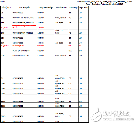
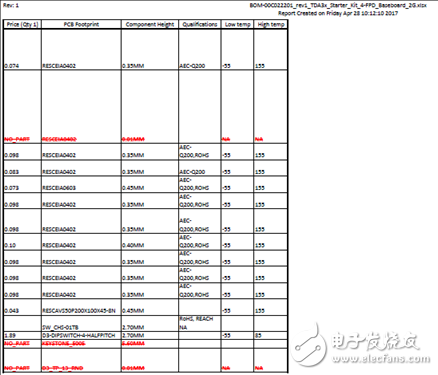


图23.多传感器平台参考设计TIDEP-01008 PCB设计图(1)

图24.多传感器平台参考设计TIDEP-01008 PCB设计图(2)

图25.多传感器平台参考设计TIDEP-01008 PCB设计图(3)

图26.多传感器平台参考设计TIDEP-01008 PCB设计图(4)

图27.多传感器平台参考设计TIDEP-01008 PCB设计图(5)

图28.多传感器平台参考设计TIDEP-01008 PCB设计图(6)

图29.多传感器平台参考设计TIDEP-01008 PCB设计图(7)

图30.多传感器平台参考设计TIDEP-01008 PCB设计图(8)

图31.多传感器平台参考设计TIDEP-01008 PCB设计图(9)

图32.多传感器平台参考设计TIDEP-01008 PCB设计图(10)
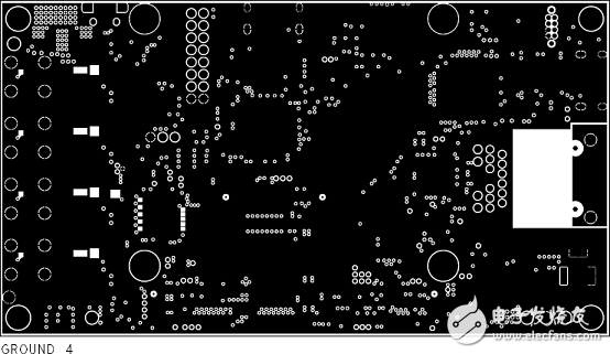
图33.多传感器平台参考设计TIDEP-01008 PCB设计图(11)
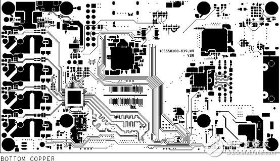
图34.多传感器平台参考设计TIDEP-01008 PCB设计图(12)

图35.多传感器平台参考设计TIDEP-01008 PCB设计图(13)
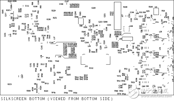
图36.多传感器平台参考设计TIDEP-01008 PCB设计图(14)
详情请见:
和
以及
tidrya8.pdf
tda3.pdf
-
LP8733-Q1和LP8732-Q1为DRA78x和TDA3x供电的用户指南2024-12-24 585
-
为DRA78x和TDA3x供电的TPS65919-Q1和TPS65917-Q1用户指南2024-12-04 611
-
TDA3x中作为电压监控的ADC2024-10-11 378
-
TDA3x SoC15mm封装(ABF)器件版本2.0数据表2024-08-07 592
-
具有MIPI CSI-2输出的汽车ADAS参考设计2022-09-14 2206
-
关于汽车电子上多传感器平台的设计参考2020-05-22 1041
-
汽车电子上的多传感器平台参考设计2019-09-30 1322
-
面向基于低功耗TDA3x的系统汽车电源解决方案2018-11-23 3317
-
具有MIPI CSI-2输出的汽车ADAS参考设计包括BOM及层图2018-09-27 2838
-
TDA2x SoC系列支持Vision AccelerationPac,助力客户创建高级驾驶员辅助系统2018-09-20 2445
-
汽车ADAS系统中的传感器2018-09-11 4423
-
TDA3x SoC让我们驾车更安全2018-04-30 6051
-
汽车电源低功耗TDA3x-Based系统设计指南2017-05-04 969
全部0条评论

快来发表一下你的评论吧 !
