

Powerint LNK406EG 14W PWM-模拟调光LED驱动方案
移动通信
描述
关键词: LED驱动 , LNK406EG , Powerint , PWM , 模拟调光
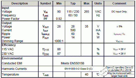
Powerin的参考设计DER263是采用LinkSwitchTM-PH系列LNK406EG的14W PWM-模拟调光LED驱动器,LED串的电压电流为28V/500A,输入电压范围从90VAC到265VAC,高效率,230VAC时的PFC大于87%,115VAC时的PFC大于86%,功率因素大于0.9,满足EN61000-3-2 Class C,1000:1调光范围.本文介绍了14W PWM-模拟调光LED驱动器主要特性和指标,电路图,材料清单与PCB布局图.
2012-1-18 12:23:53 上传
The document describes a high power-factor secondary referenced, analog dimmable LED driver. The circuit is designed to drive a nominal LED string voltage of 28 V at 500 mA from an input voltage range of 90 VAC to 265 VAC. The LED driver utilizes the LNK406EG from the LinkSwitch-PH family of ICs.
Analog dimming is controlled by an external secondary referenced analog control signal of 0-10 V. 0 volts correspond to minimum light output and 10 V corresponds to maximum brightness. The analog controlled signal is transferred to the primary-side and controls the feedback current IFB of LNK406EG which in turn controls the output power/light output of the driver while maintaining high power factor and low THD.
An active load circuit and control are also included to extend dimming ratio beyond 1000:1 but may be omitted if extended dimming operation is not required.
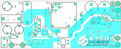
This document contains the LED driver specification, schematic, PCB diagram, bill of materials, conducted EMI measurements, thermal measurements, transformer documentation and typical performance characteristics.
14W PWM-模拟调光LED驱动器主要特性:
High efficiency, power factor corrected
o >87% at 230 VAC and >86% at 115 VAC
o >0.9 PF, meets EN61000-3-2 Class C
0-10 V analog dimming
o >1000:1 dimming range
Low cost, low component count and small printed circuit board footprint
o No current sensing required
o Frequency jitter for smaller, lower cost EMI filter components
Integrated protection and reliability features
o Output open circuit / output short-circuit protected with auto-recovery
o Line input overvoltage shutdown extends voltage withstand during line faults.
o Auto-recovering thermal shutdown with large hysteresis protects both components and printed circuit board
2012-1-18 12:23:53 上传
下载附件 (91.37 KB)图1.14W PWM-模拟调光LED驱动器外形图:上:顶视图,下:底视图
14W PWM-模拟调光LED驱动器主要指标:
2012-1-18 12:23:53 上传
下载附件 (25.52 KB)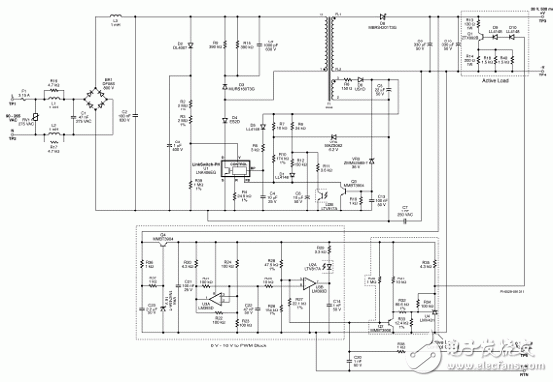
2012-1-18 12:23:53 上传
下载附件 (40.12 KB)图2.14W PWM-模拟调光LED驱动器电路图
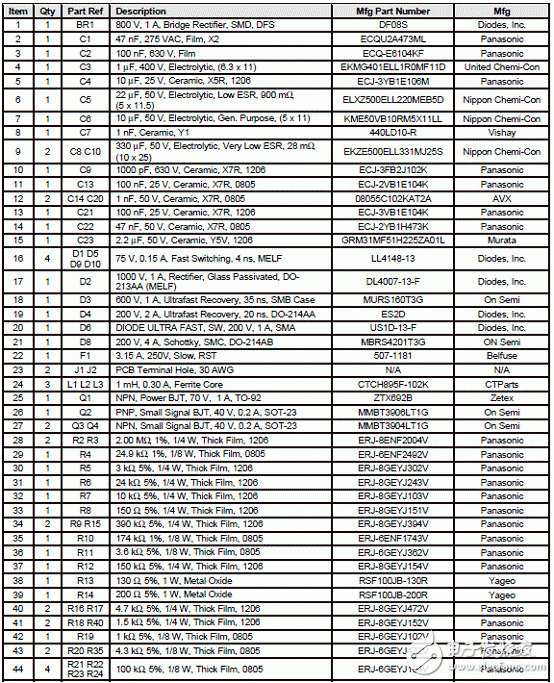
14W PWM-模拟调光LED驱动器材料清单:
2012-1-18 12:23:53 上传
下载附件 (114.73 KB)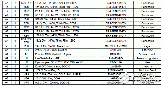
2012-1-18 12:23:53 上传
下载附件 (47.2 KB)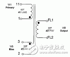
2012-1-18 12:23:53 上传
下载附件 (5.55 KB)图3.变压器框图
2012-1-18 12:23:53 上传
下载附件 (30.95 KB)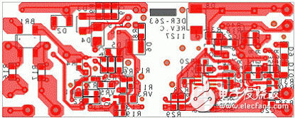
2012-1-18 12:23:53 上传
下载附件 (44.9 KB)图3.14W PWM-模拟调光LED驱动器PCB布局图:上:顶层,下:低层
详情请见:
der263[1].pdf (8.47 MB, 下载次数: 3)
2012-1-18 12:23:23 上传
下载次数: 3下载积分: 积分 -1
- 相关推荐
- 热点推荐
-
基于LNK14EG设计的406瓦LED驱动器电子电路2023-10-15 2902
-
#调光电源芯片方案#PWM调光/模拟调光无频闪LED驱动芯片FP71952021-08-17 14525
-
LNK405EG: 15W PAR38 TRIAC调光LED驱动方案2019-03-26 785
-
Powerint LNK409EG 25W T8管LED驱动解决方案2019-03-18 930
-
Powerint LNK457DG高效3.8W可调光LED驱动方案2019-03-13 804
-
Powerint LNK419EG 18W T8管灯LED驱动设计方案2019-03-11 1172
-
Powerint LNK302 150W LED街灯照明参考设计2019-02-24 1059
-
Powerint LNK420EG 75W LED驱动解决方案2019-02-17 881
-
Powerint LNK419EG 40.5W街灯LED照明解决方案2019-02-12 843
-
SM2213EA 14W三段调光调色LED恒流驱动电源方案2016-04-14 3652
-
LNK403-409EG设计的带TRIAC调光LED驱动技术2010-10-19 1812
-
基于LinkSwitch-PH设计的14W TRIAC调光L2010-06-23 2098
全部0条评论

快来发表一下你的评论吧 !

