

ADI ADMV1013 24-44GHz宽带微波升频器解决方案
嵌入式技术
描述
ADI公司的ADMV1013是24GHz至44GHz 宽带微波升频器,提供两种升频转换模式:从基带 I/Q 直接转换为 RF和从实际 IF 进行单边带升频转换,LO输入频率范围从5.4GHz至10.25 GHz,可实现高达41GHz的LO四倍频器,工作温度−40℃到+85℃,主要用在点对点微波无线电,雷达,电子战争系统,仪表和自动测试设备(ATE).而ADMV1013-EVALZ评估板将ADMV1013与微控制器,低压差(LDO)稳压器和AD5601 nanoDAC®结合在一起,可以快速轻松地评估ADMV1013.微控制器可以让用户通过分析,控制和评估(ACE)软件配置ADMV1013寄存器映射.LDO 稳压器支持由单一电源为 ADMV1013 供电,并提供电源纹波抑制功能.AD5601 nanoDAC让用户在不使用外部电源的情况下衰减来自ADMV1013的混频器的射频(RF)功率.本文介绍了ADMV1013主要特性,功能框图,以及评估板ADMV1013-EVALZ主要特性,配置图,实验室建立图,电路图,材料清单和PCB设计图.
The ADMV1013 is a wideband, microwave upconverter optimized for point to point microwave radio designs operating in the 24 GHz to 44 GHz radio frequency (RF) range.
The upconverter offers two modes of frequency translation. The device is capable of direct conversion to RF from baseband in-phase quadrature (I/Q) input signals, as well as single-sideband (SSB) upconversion from complex intermediate frequency (IF) inputs. The baseband I/Q input path can be disabled and modulated complex IF signals, anywhere from 0.8 GHz to 6.0 GHz, can be inserted in the IF path and upconverted to 24 GHz to 44 GHz while suppressing the unwanted sideband by typically better than 26 dBc. The serial port interface (SPI) allows adjustment of the quadrature phase and mixer gate voltage to allow optimum sideband suppression and local oscillator (LO) nulling. In addition, the SPI interface allows powering down the output envelope detector to reduce power consumption.
The ADMV1013 upconverter comes in a 40-terminal land grid array package (LGA) package. The ADMV1013 operates over the −40℃ to +85℃ case temperature range.
ADMV1013主要特性:
Wideband RF input frequency range: 24 GHz to 44 GHz
2 upconversion modes
Direct conversion from baseband I/Q to RF
Single-sideband upconversion from real IF
LO input frequency range: 5.4 GHz to 10.25 GHz
LO quadrupler for up to 41 GHz
Matched 50 Ω single-ended RF output and IF inputs
Option between matched 100 Ω balanced or 50 Ω single-ended LO inputs
100 Ω balanced baseband inputs
Sideband suppression and carrier feedthrough optimization
Variable attenuator for transceiver power control
Programmable via 4-wire SPI interface
40-terminal land grid array package (LGA)
ADMV1013应用:
Point to point microwave radios
Radar, electronic warfare systems
Instrumentation, automatic test equipment (ATE)
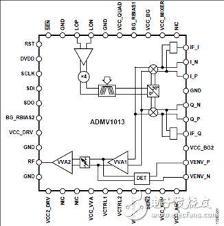
图1.ADMV1013功能框图
评估板ADMV1013-EVALZ
The ADMV1013-EVALZ evaluation board incorporates the ADMV1013 with a microcontroller, low dropout (LDO) regulators, and the AD5601 nanoDAC® to allow the quick and easy evaluation of the ADMV1013. The microcontroller allows the user to configure the ADMV1013 register map through the Analysis, Control, Evaluation (ACE) software. The LDO regulators allow the ADMV1013 to be powered on by a single supply, and offer power supply ripple rejection. The AD5601 nanoDAC allows the user to attenuate the radio frequency (RF) power from the mixer of the ADMV1013 without using an external power supply.
The ADMV1013 is a silicon germanium (SiGe) design, wideband, microwave upconverter optimized for point to point microwave radio designs operating in a frequency range of 24 GHz to 44 GHz.
The ADMV1013 comes in a compact, thermally enhanced, 6 mm × 6 mm LGA package, and operates over a temperature range of −40℃ to +85℃. For full details on the ADMV1013, see the ADMV1013 data sheet. Consult the data sheet in conjunction with this ADMV1013-EVALZ user guide when using the ADMV1013-EVALZ evaluation board.
评估板ADMV1013-EVALZ主要特性:
Full feature evaluation board for the ADMV1013
On-board USB for SPI control
5 V operation
ACE software interface for SPI control
图2.评估板ADMV1013-EVALZ外形图
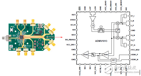
图3.评估板ADMV1013-EVALZ配置图
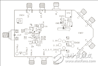
图4.评估板ADMV1013-EVALZ顶视图
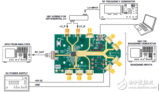
图5.评估板ADMV1013-EVALZ I/Q输入实验室建立图
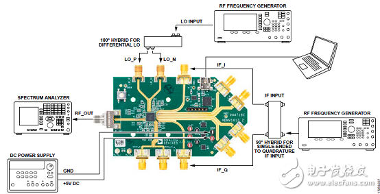
图6.评估板ADMV1013-EVALZ IF输入实验室建立图
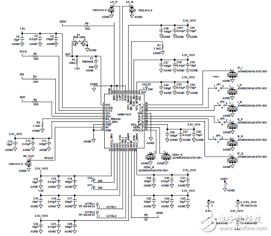
图7.评估板ADMV1013-EVALZ电路图:ADMV1013连接
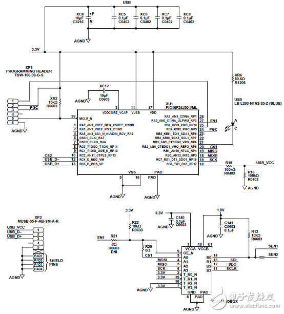
图8.评估板ADMV1013-EVALZ电路图:MCU和电平转换器连接
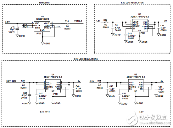
图9.评估板ADMV1013-EVALZ电路图:LDO稳压器连接
评估板ADMV1013-EVALZ材料清单:
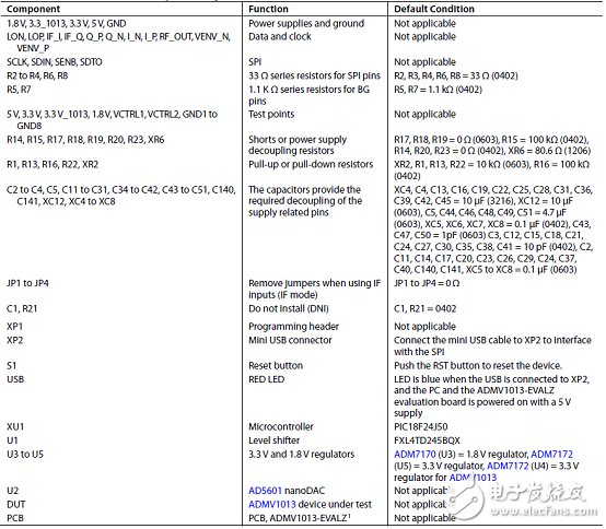
图10.评估板ADMV1013-EVALZ正面图
图11.评估板ADMV1013-EVALZ背面图
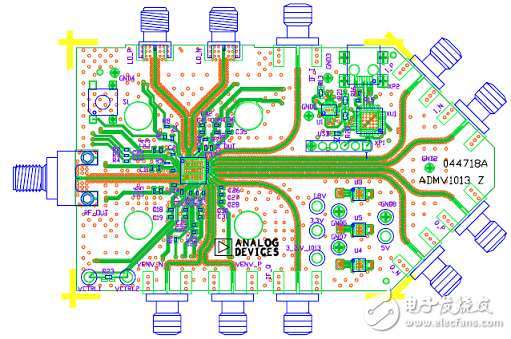
图12.评估板ADMV1013-EVALZ PCB布局图:顶层
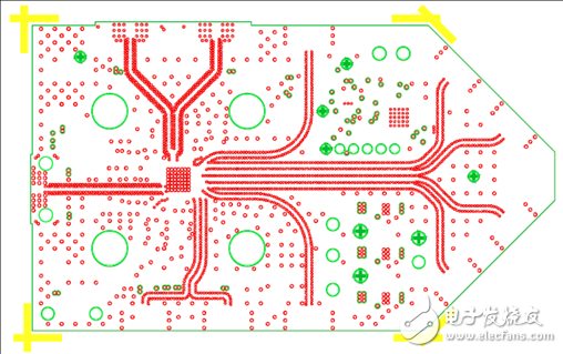
图13.评估板ADMV1013-EVALZ PCB布局图:第二层
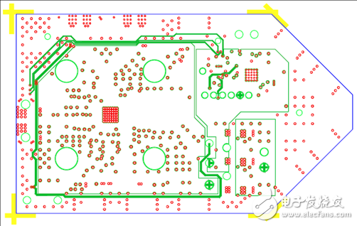
图14.评估板ADMV1013-EVALZ PCB布局图:第三层
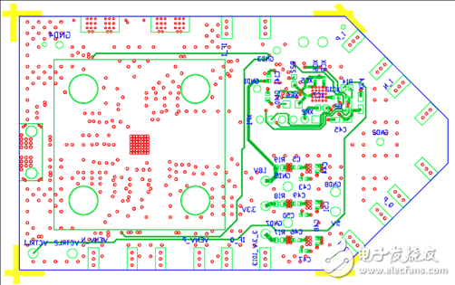
图15.评估板ADMV1013-EVALZ PCB布局图:底层
- 相关推荐
- 热点推荐
- A
-
ADMV1014:24 GHz - 44 GHz宽带微波下变频器的全面解析2026-04-30 209
-
ADMV1013S 24 GHz 至 44 GHz、宽带、微波上变频器技术手册2025-02-28 1234
-
ADMV1014:24 GHz至44 GHz,宽带,微波下变频器数据表2021-04-27 926
-
ADMV1013 S参数2021-03-23 774
-
ADMV1013 S-Parameters2021-02-03 650
-
24 GHz至44 GHz宽带集成上变频器和下变频器可提升微波无线电性能,同时缩小尺寸2019-08-28 5874
-
ADMV1013ACCZ微波升频器产品介绍2019-07-09 1455
-
ADI ADMV1014 24-44GHz宽带微波下变频器解决方案2019-04-05 4506
-
关于使用SiGe和28nm CMOS的24GHz至44GHz无线电完整解决方案2018-08-01 3850
全部0条评论

快来发表一下你的评论吧 !
