

ADuM4137单路IGBT栅极驱动解决方案
电子说
描述
ADI公司的ADuM4137是单路IGBT栅极驱动器,采用ADI的iCoupler®技术,使得输入信号和输出栅驱动之间绝缘。器件还对过流,遥控温度过热,欠压锁住(UVLO)和热关断(TSD)等事件提供故障报告。峰值驱动输出6A,NFET内部关断时开态电阻小于0.95Ω,PFET关断时开态电阻小于1.18Ω,上升传输时延105ns,下降传输时延107ns,最小脉冲宽度70ns,工作结温范围为−40℃到+150℃,满足汽车应用AEC-Q100规范,主要用在MOSFET/IGBT栅极驱动器,光伏(PV)逆变器,马达驱动和电源。本文介绍了ADuM4137主要特性,功能框图,IGBT驱动应用案例电路以及评估板EVAL-ADuM4137EBZ主要特性,电路图,材料清单和PCB设计图。
The ADuM41371 is a single-channel gate driver specifically optimized for driving insulated gate bipolar transistors (IGBTs)。 Analog Devices, Inc., iCoupler® technology provides isolation between the input signal and the output gate drive.
The Analog Devices chip scale transformers also provide isolated communication of control information between the high voltage and low voltage domains of the chip. Information on the status of the chip can be read back from the dedicated fault outputs. The ADuM4137 provides isolated fault reporting for overcurrent events, remote temperature overheating events, undervoltage lockout (UVLO), and thermal shutdown (TSD)。
Integrated onto the ADuM4137 is an overcurrent detection feature that protects the IGBT in case of overcurrent events. The split emitter overcurrent detection is coupled with a high speed, two-level turn off in case of faults.
The ADuM4137 provides a Miller clamp control signal for the external metal-oxide semiconductor field effect transistor (MOSFET) to provide robust IGBT turn off with a single rail supply when the gate voltage drops below 2.0 V (typical) and above GND2. Operation with unipolar secondary supplies is possible, with or without the Miller clamp operation.
A low gate voltage detection circuit can trigger a fault if the gate voltage does not go above the internal threshold (VDVL) within the time allowed from turn on (tDVL)。 This circuit allows detection of IGBT device failures that exhibit gate shorts or other causes of weak drive.
The secondary falling UVLO is set to 11.24 V (typical) for common IGBT two-level plateau voltage levels.
The ADuM4137 provides for in field programming of temperature. Two temperature sensor pins allow isolated monitoring of system temperatures at the IGBTs, sensing diode gains and offsets by means of a serial port interface (SPI) bus on the primary side of the device. Values are stored on an EEPROM located on the secondary side. Additionally, programming is available for specific voltage offsets, temperature sensing reporting frequencies, and important delays.
The ASC pin on the secondary side on the ADuM4137 allows the driver to be switched on from the secondary side if no faults are present.
ADuM4137主要特性:
6 A peak drive output capability
Internal turn off NFET, on resistance: 《0.95 Ω
Internal turn on PFET, on resistance: 《1.18 Ω
Split emitter overcurrent detection
Miller clamp output with gate sense input
Isolated fault output
Isolated temperature sensor read back
Propagation delay
Rising: 105 ns typical
Falling: 107 ns typical
Minimum pulse width: 70 ns
Operating junction temperature range (−40℃ to +150℃)
VDD1 and VDD2 UVLO
ASC input
8.3 mm creepage distance
Safety and regulatory approvals
5 kV rms for 1 minute per UL 1577
CSA Component Acceptance Notice 5A
DIN V VDE V 0884-10 (VDE V 0884-10):2006-12
VIORM = 849 VPEAK (reinforced/basic)
AEC-Q100 qualified for automotive applications
ADuM4137应用:
MOSFET/IGBT gate drivers
Photovoltaic (PV) inverters
Motor drives
Power supplies
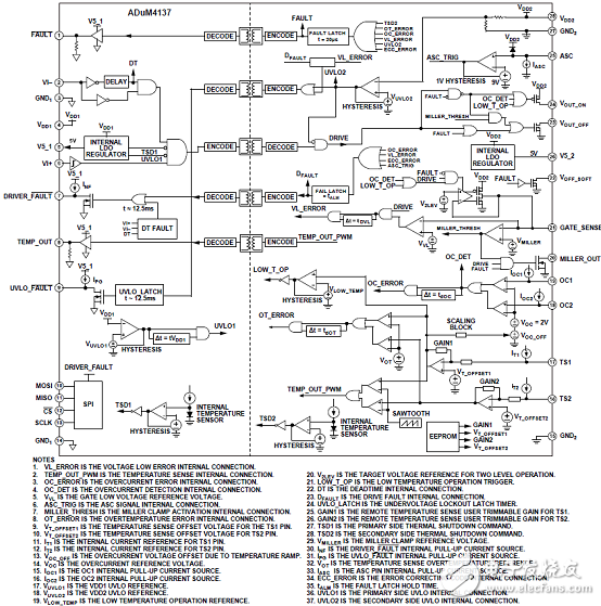
图1.ADuM4137功能框图
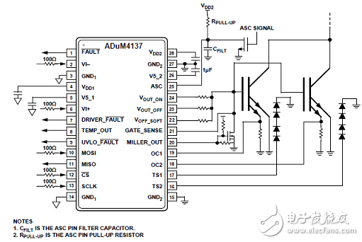
图2.ADuM4137 IGBT驱动应用案例电路
评估板EVAL-ADuM4137EBZ
The EVAL-ADuM4137EBZ board demonstrates the advanced features of the ADuM4137 while maintaining flexibility in a testing environment. The EVAL-ADuM4137EBZ board layout delivers a circuit that is easy to manipulate via jumper pins. A more optimized layout is possible and increases the performance of the system.
The EVAL-ADuM4137EBZ board works with the USB-SDP-CABLEZ programming cable to access the secondary side electronically erasable programmable read only memory (EEPROM) and includes the option to drive the serial peripheral interface (SPI) bus with any other SPI compatible system. The USB-SDP-CABLEZ operates with a 3.3 V logic supply, while the ADuM4137 has an internal 5 V regulator. A resistor divider on the MISO line is included in the R21 and R22 resistors to allow interfacing.
This guide demonstrates how to use the ADuM4137 evaluation software for accessing the user trim bits and explains how to simulate EEPROM settings and program bits into nonvolatile memory.
For full details on the ADuM4137, see the ADuM4137 data sheet, which should be consulted in conjunction with this user guide when using this evaluation board.
评估板EVAL-ADuM4137EBZ主要特性:
6 A peak drive output capability
Output power device resistance: 《1 Ω
Test infrastructure for
SPI communication
Miller clamp
Desaturation detection
Two overcurrent protection pins
Two temperature sensor pins
Fault reporting
Two dummy loads
图3.评估板EVAL-ADuM4137EBZ外形图
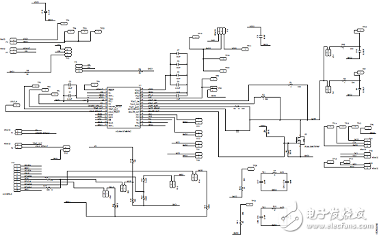
图4.评估板EVAL-ADuM4137EBZ电路图
评估板EVAL-ADuM4137EBZ材料清单:
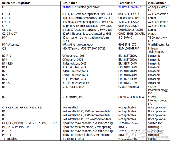
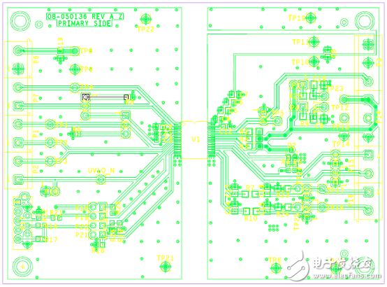
图5.评估板EVAL-ADuM4137EBZ PCB设计图:顶层
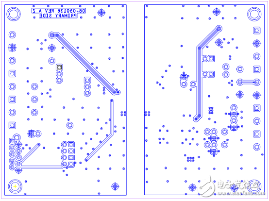
图6.评估板EVAL-ADuM4137EBZ PCB设计图:底层
- 相关推荐
- 热点推荐
- �
-
ADUM4135单电源/双电源高电压隔离IGBT栅极驱动器技术手册2025-06-04 1046
-
ADuM4137具有故障检测功能的高电压隔离式IGBT栅极驱动器技术手册2025-05-30 816
-
ADuM4135:提供米勒箝位的单电源/双电源 高电压隔离IGBT栅极驱动器2023-11-29 639
-
适合于IGBT栅极驱动器偏置的四路输出隔离式Fly-Buck电源参考设计2022-09-26 6194
-
EVAL-ADuM4137 EVAL-ADuM4137评估板2021-07-12 270
-
UG-1438:使用故障检测评估ADuM4137<em>i</em>耦合器<sup>®</sup>高压隔离IGBT栅极驱动器2021-05-16 803
-
UG-854:ADuM4135<span class=“模拟耦合器”>I</span>耦合器评估板,单/双电源,高压隔离IGBT栅极驱动器,带密勒钳位2021-04-24 809
-
ADuM4137评估软件LabVIEW源代码2021-03-23 614
-
ADuM4135:提供米勒箝位的单电源 / 双电源 高电压隔离 IGBT 栅极驱动器2021-03-21 884
-
ADUM4137 IBIS Model2021-02-03 691
-
ADuM4137 Evaluation Software Labview Source Code2021-02-02 560
-
支持ADuM3123CRZ隔离式精密栅极驱动器的EVAL-ADUM3123EBZ2019-05-06 1794
-
四路输出隔离式IGBT栅极驱动Fly-Buck电源包括BOM及层图2018-09-05 3036
-
IGBT的栅极驱动2010-08-31 1572
全部0条评论

快来发表一下你的评论吧 !
