

电力线监控的精确采样和特性分析
智能电网
描述
国际即时新闻(原文:英文)
Multichannel Sampling Keys Accurate Power Line Monitoring
Accurate power-line monitoring has emerged as a critical requirement not only centrally within the power grid itself but also at its edges. For grid-tied energy-harvesting power-generation systems and even for end equipment, ongoing analysis of power quality characteristics helps ensure the health of the grid and attached systems. At the heart of power-monitoring systems, analog-digital converters (ADCs) play a key role in measuring line voltage and current at a level of accuracy appropriate to each application. Engineers can meet a range of requirements—from utility-grade systems with accuracy needed for revenue purposes to basic power monitors for detecting line faults—using high-performance ADCs and associated components from manufacturers including Analog Devices, Copal Electronics, Intersil, Linear Technology, Maxim Integrated, Microchip Technology, ON Semiconductor, Pulse Electronics, and Texas Instruments.
At the most basic level, power-monitoring systems rely on measurement of instantaneous current and voltage using current transformers (CTs) and voltage transformers (termed PT, for potential transformers) output converted by high-speed ADCs (Figure 1). In turn, a processor uses the instantaneous current and voltage measurements to calculate key characteristics including active power, reactive power, apparent power, and power factor—and even more complex calculations such as harmonics, which can result in equipment damage.
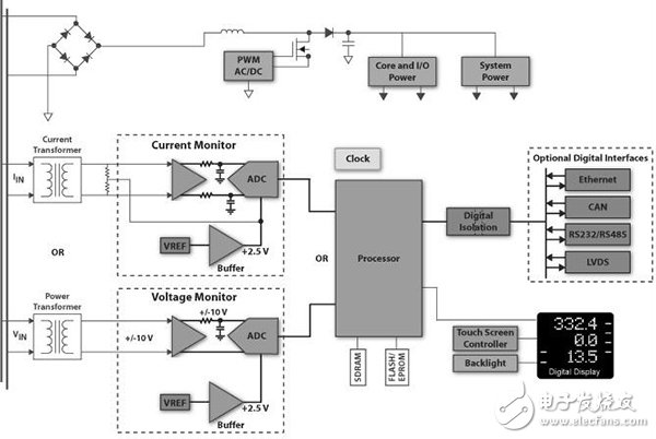
Figure 1: A typical power-monitoring system samples line current and voltage, using high-speed analog-digital converters (ADCs) to provide high-resolution data to the host processor for calculation of power parameters. (Courtesy of Texas Instruments)
Performing these power calculations depends foremost on accurately measured voltage and current. Standards such as ANSI C12.20 for North America and IEC 62053 dictate specific accuracy levels such as Class 0.2, which requires ± 0.2 percent accuracy. In practice, power-measurement systems are typically designed to surpass standard accuracy specifications—relying on high-sample rates and high-resolution converters to capture high-speed transients and to ensure reliable calculation of more complex characteristics such as multiple harmonics.
At the same time, measurement of these power characteristics requires tightly synchronized, high-resolution measurement of voltage and current across all three phases and neutral. Synchronized sampling allows extremely accurate measurement of phase angle between voltage and current on each line. Poor synchronization between voltage and current measurements can introduce artifacts, reduce overall accuracy, and significantly compromise more complex power calculations.
Simultaneous sampling
To reduce the complexity of high-accuracy multichannel measurement, designers can turn to highly integrated devices that combine high-resolution ADCs with analog front ends (AFEs) designed to optimize impedance matching, signal dynamic range, offset, and other factors that can erode performance and accuracy of data conversion. Manufacturers typically build these high-performance simultaneous sampling ADCs around successive-approximation register (SAR) converters. SAR ADCs offer high accuracy without the cycle latency associated with the oversampling used in delta-sigma ADCs to achieve high stability and conversion resolution.
For the most demanding applications, semiconductor manufacturers integrate a complex AFE and dedicated SAR ADC for each channel. For highly accurate power monitoring, eight-channel ADCs such as the Maxim Integrated MAX11046 and Texas Instruments ADS8568 allow simultaneous sampling of all three phases and neutral (Figure 2). With a dedicated AFE and ADC for each channel, these devices are able to achieve very high data rates—250 ksps per channel for the MAX11046 and 510 ksps for the ADS8568 (parallel-output interface).
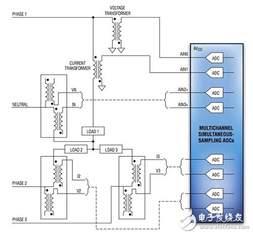
Figure 2: For three-phase power monitoring, simultaneous sampling ADCs provide separate AFEs and ADCs for each of the eight channels required for highly accurate power calculations. (Courtesy of Maxim Integrated)
For some applications, designers can simply tie the unbuffered output of CTs and PTs directly into the inputs of ADCs including the Maxim Integrated MAX11046 and TI ADS8568 as suggested in Figure 2. Devices such as the MAX11046 provide high-input input impedance and self-protecting input clamps to support this type of simple configuration. To achieve maximum throughput, however, ADCs typically require op amp drivers between the transducers and ADC. In fact, evaluation boards from both Maxim Integrated and Texas Instruments include such drivers. On its MAXREFDES30 evaluation board for the MAX11046, Maxim Integrated includes its MAX44252 op amp drivers. On the TI ADS8688EVM-PDK evaluation board for the ADS8568, Texas Instruments includes its OPA2209 op amp drivers.
Less-stringent requirements
For power monitoring applications with less stringent accuracy requirements, designers can turn to devices with more modest performance attributes. The simpler requirements in a power monitor that only needs to detect faults in the power line can take advantage of lower resolution ADCs. The Texas Instruments LMP92064 current/voltage monitor IC uses this approach to offer a single-line power-monitoring IC that requires few additional components (Figure 3). The device integrates a precision current sense amplifier to measure a load current across a shunt resistor and a buffered voltage channel to measure the voltage supply of the load. Nevertheless, the ability to sample current and voltage channels simultaneously by the independent 125-kSps, 12-bit ADCs supports accurate power calculations.
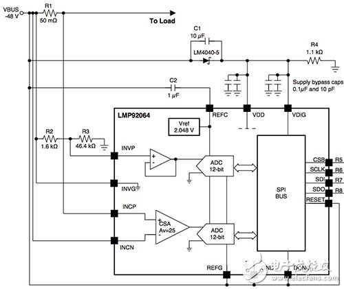
Figure 3: Power-monitor ICs such as the Texas Instruments LMP92064 use a pair of 12-bit ADCs to support power calculations for applications with less-demanding accuracy requirements. (Courtesy of Texas Instruments)
For even simpler monitoring requirements, designers can often use a single ADC with an external multiplexer to monitor voltage and current on each line. In fact, 8:1 multiplexers such as the Intersil DG408, Maxim Integrated MAX4581, and ON Semiconductor MC74HC4051A can support three-phase applications that require more basic power monitoring.
Designers can find ADCs with integrated multiplexers designed to support a broad range of channels, data throughput, and conversion resolution. For three-phase power monitoring, devices such as Analog Devices AD7699, Linear Technology LTC2372, and Texas Instruments ADS8688 integrate an eight-channel multiplexer with ADC and dedicated analog front end for each channel. For example, each input channel of the TI ADS8688 includes over-voltage protection, a programmable gain amplifier (PGA), low-pass filter, and driver feeding the shared multiplexer to the single ADC.
Conclusion
Ensuring grid power quality requires highly accurate measurement of voltage and current on each phase. For grid-tied energy-harvesting systems and equipment, power monitoring similarly requires high-resolution, simultaneous sampling of line voltage and current using ADCs providing a dedicated converter for each channel. Although basic fault monitoring builds on the same principles as high-accuracy measurement applications, designers can use lower-resolution ADCs or multiplexed devices that offer high-resolution multichannel measurement at lower throughput rates. Designers can find ready availability of ADCs designed to meet this broad range of requirements for channel support, bit resolution, and sample rate.
自动翻译仅供参考
多通道采样精确的按键电力线监控
准确的电力线监控已在电网本身,而且在其边缘成为一个关键的要求,不仅集中。对于并网能量收集发电系统,甚至为终端设备,持续的电能质量特性分析,有助于确保电网和连接系统的健康状况。在功率监视系统的心脏,模拟 - 数字转换器(ADC)起到测量线路电压和电流的精度适合于每个应用程序的电平的关键作用。工程师可以从制造商包括Analog Devices公司,产科宝电子,Intersil公司,凌力尔特满足各种需求 - 从公用事业级系统精度所需收入的目的基本电源监视器用于检测线路故障,采用高性能ADC和相关组件, Maxim的集成,Microchip的科技,安森美半导体,电子脉冲和德州仪器。
在最基本的层面上,电力监控系统依赖于瞬时电流和电压使用电流互感器(CT)和电压互感器的测量(称为PT,用于电压互感器)的输出转换成由高速ADC(图1)。反过来,一个处理器使用的瞬时电流和电压测量值来计算密钥的特性,包括有功功率,无功功率,视在功率和功率因数 - 甚至更复杂的计算,例如谐波,这会导致设备损坏。
德州仪器典型的电力监控系统的图像
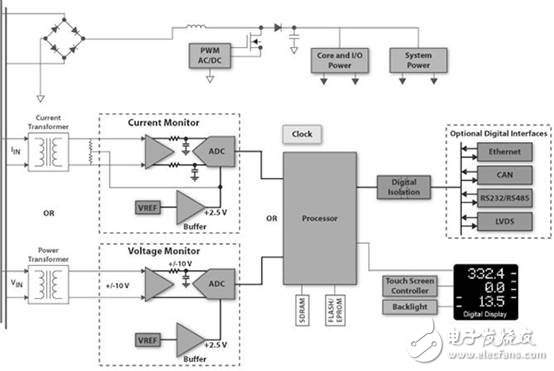
图1:典型的电力监控系统的样品线路电流和电压,采用高速模拟 - 数字转换器(ADC),提供高分辨率的数据,以用于电力参数计算的主处理器。 (德州仪器提供)
执行这些功率计算取决于最前面上精确地测量电压和电流。如ANSI C12.20北美和IEC 62053标准规定的特定精度水平,如0.2级,这需要±0.2%的精度。在实践中,功率测量系统通常被设计为超越标准精度规格-依靠高采样率和高分辨率的转换器,以捕捉高速瞬变,并确保更复杂的特性,例如多谐波可靠的计算。
与此同时,这些功率特性的测量需要紧密同步的,电压和电流在所有三个阶段和中性的高分辨率测量。同步采样允许的电压和电流,每行之间的相位角的非常精确的测量。电压和电流测量之间缺乏同步可以引入假象,降低整体精度,显著妥协更复杂的功率计算。
同时采样
为了减少高精度多通道测量的复杂度,设计者可以转向,结合高分辨率ADC与旨在优化阻抗匹配模拟前端(AFE),信号的动态范围高度集成的器件,偏移,并且能够侵蚀性能的其他因素和数据转换的准确性。制造商通常围绕逐次逼近寄存器(SAR)转换器这些高性能同步采样ADC。 SAR ADC提供高精确度不与Δ-Σ模数转换器用于实现高稳定性和转换分辨率的过采样相关的周期延迟。
对于最苛刻的应用,半导体制造商集成了复杂的AFE和专用SAR ADC,每个通道。对于高度精确的功率监控,8通道ADC,例如Maxim的MAX11046集成和德州仪器ADS8568让所有三个阶段的同步采样和中性(图2)。为每个信道专用的AFE和ADC,这些设备都能够实现非常高的数据速率-250每个通道ksps的用于MAX11046和510 ksps时为ADS8568(并行输出接口)。
Maxim的集成的三相电源监控图像
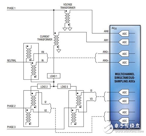
图2:三相电源监控,同时采样ADC提供了独立的AFE和ADC每个八通道需要高度精确的功率计算。 (马克西姆集成提供)
对于一些应用,设计人员可以简单地扎CT和PT的缓冲输出直接进入的ADC包括的Maxim集成MAX11046和TI ADS8568的输入,如图建议2.设备如MAX11046提供高输入的输入阻抗和自我保护输入钳位支持这种类型的简单配置。为了实现最大的吞吐量,但是,ADC通常所需要的换能器和ADC之间的运算放大器的驱动程序。事实上,无论从马克西姆集成和德州仪器评估板包括这样的驱动程序。其MAXREFDES30评估板为MAX11046,美信集成包括其MAX44252运算放大器的驱动程序。在TI ADS8688EVM-PDK评估板为ADS8568,德州仪器包括其OPA2209运放的驱动程序。
不太严格的要求
对于电力监控应用不太严格精度要求,设计人员可以转向更温和的性能属性的设备。较简单的要求功率监视器仅需要检测故障在电力线可利用较低分辨率的ADC的优势。德州仪器LMP92064电流/电压监视IC使用这种方法来提供一个单线功率监视IC,它需要很少的额外的组件(图3)。该器件集成精密电流检测放大器来测量分流电阻和一个缓冲电压信道来测量电压电源的负载的负载电流。尽管如此,由独立125-ksps的同时采样电流和电压通道的能力,12位ADC支持精确的功率计算。
德州仪器LMP92064的图
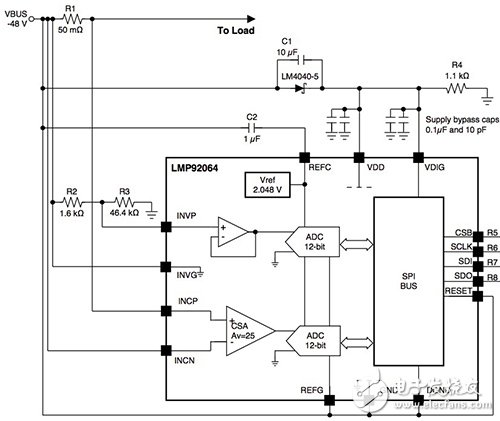
图3:功率监控器IC,例如德州仪器LMP92064使用一对12位ADC,支持功率计算与不太苛刻的精度要求的应用。 (德州仪器提供)
对于更简单的监控要求,设计人员可以经常使用单一的ADC,具有一个外部多路转换器来监视电压和电流的每一行上。事实上,8:1多路复用器,如Intersil的DG408器,Maxim Integrated MAX4581和安森美半导体MC74HC4051A可以支持需要更基本的电力监控三相应用。
设计师可以找到的ADC设计,支持广泛的渠道整合多路复用器,数据吞吐量,并转换分辨率。对于三相电源监控,如ADI公司AD7699,凌特LTC2372和德州仪器ADS8688器件集成了八通道多路复用器与ADC和专用的模拟前端为每个通道。例如,TI的ADS8688的每个输入通道包括过电压保护,可编程增益放大器(PGA),低通滤波器,并驱动进给共享多路复用到单个ADC。
结论
确保电网的电能质量要求的电压高精度测量和电流每相。对于网并列能量采集系统和设备,电力监控同样需要高分辨率,线电压的同时采样和当前使用的ADC提供专用转换器,用于每个信道。尽管基本的故障监控建立在相同的原理,高精度测量应用,设计人员可使用较低分辨率的ADC或提供高分辨率多通道测量以较低的吞吐速率复用的设备。设计师可以找到专为满足这些广泛的渠道支持,位分辨率和采样率的ADC要求现成的可用性。
-
高级电力线监控需要高性能、同步采样ADC2023-02-27 1876
-
电力线收发器SIG100的特性和应用2020-06-30 1680
-
电力线通信2018-08-29 3810
-
多通道采样的精准的电力线监测2016-02-24 4002
-
电力线前端设计2014-04-26 2828
-
电力线仿真系统的FPGA设计与实现2012-05-28 1440
-
室内低压电力线信道特性测量与分析2010-09-02 703
-
先进的电力线监测需要高性能同时采样ADC2010-04-10 775
-
电力线接入,电力线接入是什么意思2010-04-06 3325
-
中压电力线通信技术原理及应用2010-03-12 1406
-
低压电力线信道噪声特性分析2009-12-14 1671
-
中压电力线信道特性的测量及分析2009-08-13 687
-
低压电力线载波通信中信号传输特性分析2009-08-06 861
-
基于电力线载波技术的矿车监控系统2009-05-09 562
全部0条评论

快来发表一下你的评论吧 !

