

ET1100转换AX58100的设计要求及应用指南
描述
1. Introduction
This document indicates the hardware/software design notes to migrate from Beckhoff ET1100 ESC solution to AX58100 ESC solution.
2. Functions Overview
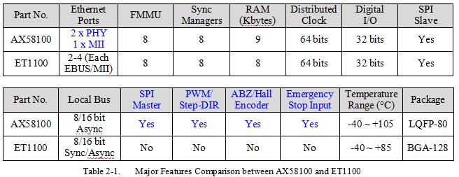
The AX58100 is a 2/3-port EtherCAT Slave Controller (ESC), licensed from Beckhoff Automation, with two integrated Fast Ethernet PHYs which support 100Mbps full-duplex operation and HP Auto-MDIX. AX58100 supports 9 Kbytes Process Data RAM, 8 Fieldbus Memory Management Units (FMMUs), 8 Sync-Managers and a 64-bit Distributed Clock.
Compared to other EtherCAT slave controller solutions, the AX58100 integrates two embedded Fast Ethernet PHYs which can support both copper and fiber industrial Ethernet applications and supports some additional interfaces such as Pulse Width Modulation (PWM), Incremental (ABZ)/Hall Encoder, SPI master, 32 Digital I/O, Emergency Stop Input, etc. for designers to easily implement AX58100 on different EtherCAT industrial fieldbus applications without extra microprocessor. The AX58100 provides SPI slave and Local bus Process Data Interfaces (PDI) to provide an easy way for system designers to implement the standard EtherCAT communication functionalities on those traditional non-EtherCAT MCU and DSP industrial platforms.
The AX58100 provides a cost-effective EtherCAT slave controller solution for industrial automation, motion/motor/Digital IO control, Digital to Analog (DAC)/Analog to Digital (ADC) converters control, sensors data acquisition, robotics, etc. industrial Ethernet fieldbus applications.
The following is the major features comparison between AX58100 and Beckhoff ET1100 ESC solutions.
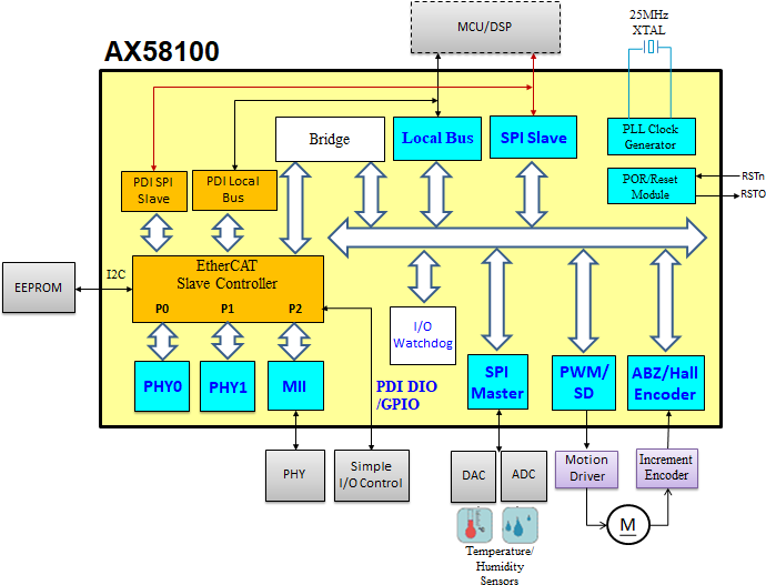
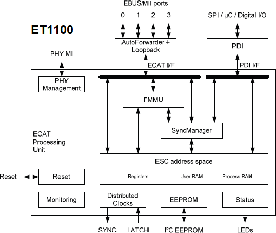
2-1. Block Diagram
The following are the block diagrams of AX58100 and ET1100.
2-2. Application Diagram
The following are the typical applications diagrams of AX58100 and ET1100. The AX58100 integrates additional interfaces such as Pulse Width Modulation (PWM), ABZ/Hall Encoder, SPI master, 32 Digital I/O, Emergency Stop Input, etc. for designers to easily implement AX58100 on different EtherCAT industrial fieldbus applications without extra microprocessor.
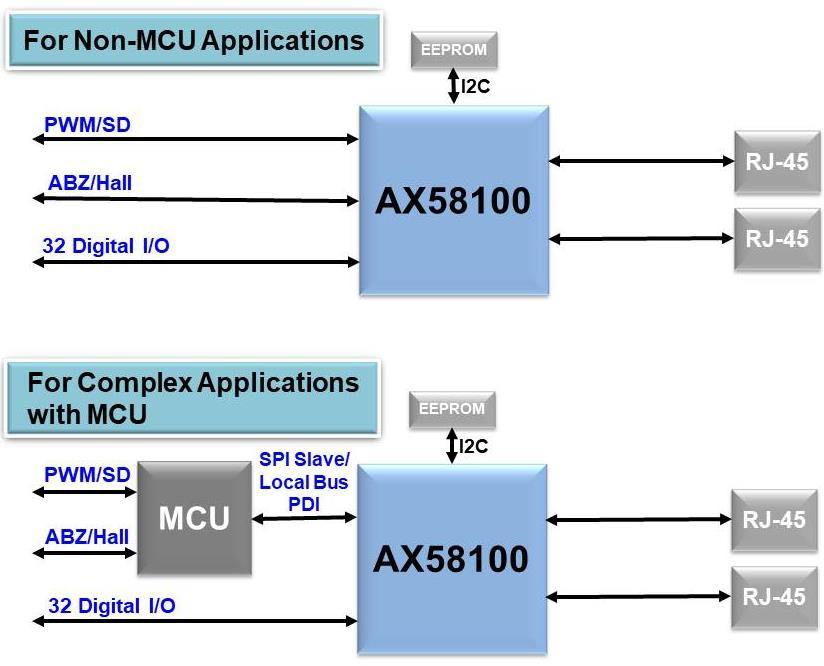
Figure 2-3. AX58100 Application Diagram
Figure 2-4. ET1100 Application Diagram
3. Hardware Transition
This section indicates the hardware design considerations while migrating from Beckhoff ET1100 ESC solution to AX58100 ESC solution.
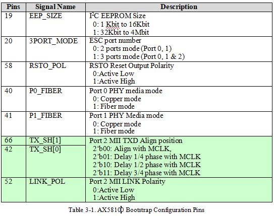
3-1. Bootstrap Hardware Configuration Pins
The AX58100 supports five multi-function bootstrap pins (pin 19, 20, 58, 40, and 41) for five hardware configurations, i.e. external I2C EEPROM size, ESC supported port number, RSTO polarity and integrated port 0/1 PHY media mode; and supports other three multi-function bootstrap pins (pin 42, 52, 66) for the configuration of port 2 MII signals. User needs to utilize an external resistor to pull up/down these bootstrap pins for correct AX58100 hardware configuration.
Beckhoff supports different hardware configuration pins based on the ET1100 product design specification. Please refer to Beckhoff ET1100 datasheet for details.
3-2. Ethernet Ports
The AX58100 ESC, which is licensed from Beckhoff Automation, supports two embedded PHYs and an optional MII interface for flexible network topology. The embedded Fast Ethernet PHYs support 100Mbps full-duplex operation and HP Auto-MDIX, and are fully compliant with the 100BASE-TX and 100BASE-FX Ethernet standards such as IEEE 802.3u, and ANSI X3.263- 1995 (FDDI-TP-PMD) for both copper and fiber industrial Ethernet applications.
The optional MII interface of AX58100 ESC is optimized for low processing/forwarding delays by omitting a transmit FIFO. To allow this, the ESC has additional requirements to Ethernet PHY, which is easily accomplished by several PHY vendors. Please refer to Beckhoff’s PHY Selection Guide to select a proper Ethernet PHY.
AX58100 Port 0 and Port 1 integrate embedded Ethernet PHYs, and Port 2 is an optional MII interface which are multi-function pins shared with others interfaces (i.e. PWM, Hall, Local Bus, Digital I/O). Packets are forwarded in the following order:
Port 0 -> EtherCAT Processing Unit -> Port 1 -> Port 2
AX58100 supports six Bootstrap pins (pin 20, 40-42, 52 and 66) for Ethernet ports hardware configurations. Please refer to Table 3-1 for details.
The following is the principle connection between AX58100 Port 2 MII interface and Ethernet PHY. The clock source of the Ethernet PHYs and ESC must be the same quartz. The TX_CLK is not connected because the ESCs do not incorporate a TX FIFO. The TX signals can be delayed inside the ESC by setting AX58100 TX_SH[1:0] bootstrap pins for TX_CLK phase shift compensation. The LINK is connected to the PHY LED output indicating a 100 Mbps (Full Duplex) link.
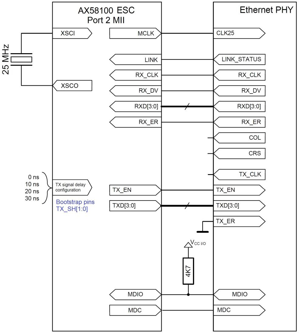
Figure 3-1. The principle connection between AX58100 Port 2 MII interface and Ethernet PHY
3-3. Digital I/O PDI
由于篇幅限制无法完整显示整篇文章,若需获取整份PDF文档,或其他相关AX58100资料,请发Mail至以下地址:info@chipreal.com
-
ax58100和lan9252区别2023-12-21 11834
-
亚信AX58100 2/3端口EtherCAT从站控制器产品简介2022-02-25 2263
-
从Beckhoff ET1100到Microchip LAN9252的移植2021-06-11 2061
-
亚信 AX58100 EtherCAT从站设备仿真功能设计教学2021-02-08 4883
-
AX58100 + STM32F303RE MCU 马达控制 参考设计指南2020-06-17 30378
-
C6748如何通过EMIFA访问ET11002020-05-25 1713
-
AX58100 + STM32F303RE MCU 马达控制参考设计指南2019-07-01 3615
-
AX58100 EtherCAT的应用优势2019-05-31 9619
-
亚信电子展出全新AX58100 EtherCAT从站控制器2018-09-06 7513
-
亚信电子推出全新AX58100 2/3端口EtherCAT从站控制器2018-03-16 12914
-
基于ET1100的EtherCAT实时工业以太网从站设计2016-09-20 4395
全部0条评论

快来发表一下你的评论吧 !
