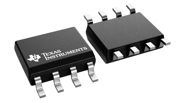
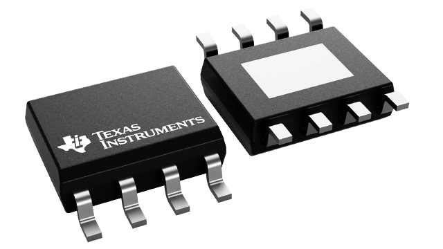
| Bus voltage (Max) (V) | 110 |
| Power switch | MOSFET |
| Input VCC (Min) (V) | 8 |
| Input VCC (Max) (V) | 17 |
| Peak output current (A) | 3 |
| Rise time (ns) | 8 |
| Operating temperature range (C) | -40 to 140 |
| Undervoltage lockout (Typ) | 8 |
| Rating | Catalog |
| Number of channels (#) | 2 |
| Fall time (ns) | 7 |
| Prop delay (ns) | 20 |
| Iq (uA) | 1 |
| Input threshold | TTL |
| Channel input logic | TTL |
| Negative voltage handling at HS pin (V) | -5 |
| Driver configuration | Non-Inverting |
- Drives Two N-Channel MOSFETs in High-Side
and Low-Side Configuration - Negative Voltage Handling on HS (–5 V)
- Maximum Boot Voltage of 120 V
- Maximum VDD Voltage of 20 V
- On-Chip 0.65-V VF, 0.6-Ω RD Bootstrap Diode
- Greater than 1 MHz of Operation
- 20-ns Propagation Delay Times
- 3-A Sink and 3-A Source Output Currents
- 8-ns Rise and 7-ns Fall Time With 1000-pF Load
- 1-ns Delay Matching
- Undervoltage Lockout for High-Side and Low-Side
Driver - Specified from –40°C to 140°C
The UCC2720x family of high-frequency N-channel MOSFET drivers include a 120-V bootstrap diode and high-side and low-side drivers with independent inputs for maximum control flexibility. This allows for N-channel MOSFET control in half-bridge, full-bridge, two-switch forward, and active clamp forward converters. The low-side and the high-side gate drivers are independently controlled and matched to 1ns between the turnon and turnoff of each other.
An on-chip bootstrap diode eliminates the external discrete diodes. Undervoltage lockout is provided for both the high-side and the low-side drivers forcing the outputs low if the drive voltage is below the specified threshold.
Two versions of the UCC27200 are offered. The UCC27200 has high noise immune CMOS input thresholds while the UCC27201 has TTL compatible thresholds.


