
资料下载


“逐次逼近法”单片混合和模块化设备
分享资料个
The most popular A→D method employed today is the successive approximation register (SAR) converter (see Box, “The Successive Approximation Technique”)。 Numerous monolithic, hybrid and modular devices embodying the successive approximation technique are available, and monolithic devices are slowly gaining in performance. Nevertheless, hybrid and modular SAR types feature the best performance. In particular, at the 12-bit level, the fastest monolithic devices currently available require about 10μs to convert. Modular and hybrid units achieve conversion speeds below 2μs, although they are quite expensive. Because of these factors, it is often desirable to build, rather than buy, a high speed 12-bit SAR converter. Even in cases where high speed is not required, lower cost may still mandate building the circuit instead of using a monolithic device.
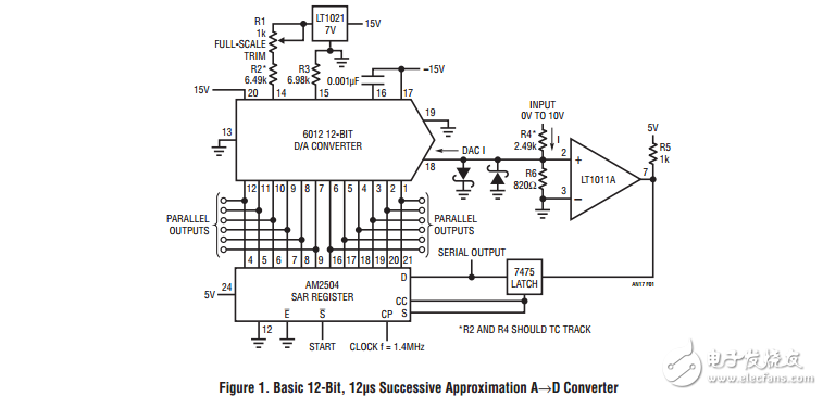
Figure 1 shows a simple 12-bit, 12μs SAR converter. Understanding this circuit’s performance limitations is useful in designing faster converters. Figure 2 shows waveforms of operation. Trace A is the clock, which is applied to the 2504 IC successive approximation register (SAR), while Trace B is the start pulse. On the rising edge of the start pulse, the SAR-DAC combination begins to test each bit, beginning with the MSB. This action is reflected in conditions at the LT1011’s positive input (Trace C)。 This waveform is seen to sequentially converge towards zero as the SAR, DAC and comparator servo the node. After the LSB has been converted the “conversion complete” (CC) line (Trace D) goes high, signaling the end of the sequence. The 7475 latch prevents the comparator from responding to input noise or shifts after the conversion is complete. It is reset at the next “conversion command”。 The major limitations on speed in this circuit are the DAC and the comparator. Most bipolar DACs require 150ns to 200ns to settle for a worst-case (full-scale) step and the comparator’s delay time must also be accounted for. The clamp diodes limit overdrive, aiding comparator response. Additionally, the 820Ω resistor to ground shunts the DACs output capacitance, helping the comparator-DAC node settle more quickly. The shunt degrades the voltage perLSB available to the comparator, but the LT1011’s high gain makes up for this.

声明:本文内容及配图由入驻作者撰写或者入驻合作网站授权转载。文章观点仅代表作者本人,不代表电子发烧友网立场。文章及其配图仅供工程师学习之用,如有内容侵权或者其他违规问题,请联系本站处理。 举报投诉
- 相关下载
- 相关文章


