
资料下载


基于NODEMCU ESP8266板和6通道继电器的家庭自动化板
分享资料个
描述
您好,欢迎回来。
这是一款基于 NODEMCU ESP8266 板和 6 通道继电器的家庭自动化板。
该板通过任何浏览器访问其 Web 应用程序在本地控制,它目前可以控制 6 种不同的输出,但我们可以添加更多,并且很容易更改额外输出的代码。
该项目的目标是制作一个简单易用的家庭自动化系统,任何人都可以通过几个简单的步骤来制作和学习。
让我们开始吧。
所需材料
以下是该项目中使用的东西-
- ESP8266 NodeMCU
- 6通道继电器模块
- PCB面包板
- 面包板
- 发光二极管
- 母头针
- USB 微型 THT 端口
- 用于焊接的铜线或引线
基本面包板设置
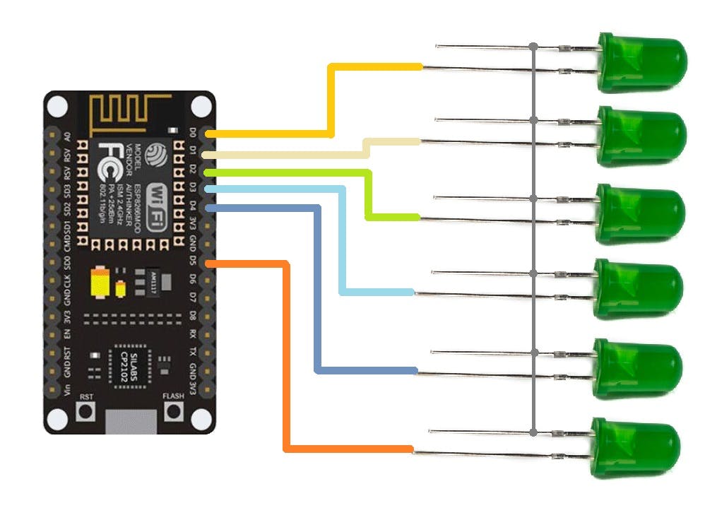
我们首先准备面包板设置,该设置由与 ESP8266 Nodemcu 板的 D0、D1、D2、D3、D4 和 D5 引脚连接的六个 LED 组成。
正在使用 NodeMCU,但任何 ESP8266 板都可以在这里使用,我们甚至可以通过使用最小的 ESP8266 设置来准备使用 ESP12F 或 12E 模块的设置。
- 我们将 LED 与 ESP8266 的 GPIO 引脚连接,如上述接线 Draigarm 中所述,并在其中上传主草图。
- 只需确保在上传之前更改草图中的 SSID 和密码即可。
结果
- 上传 Sketch 后,我们打开串口监视器并等待 ESP 与本地 WIFI 网络连接。
- 当 ESP 连接到网络时,您将看到本地 IP 地址,复制此 IP 地址并在浏览器中打开它。
- 我们现在可以通过按下 Web 应用程序中的按钮来切换 LED。
下一步,使用 PCB BREADBOARD 准备自定义设置
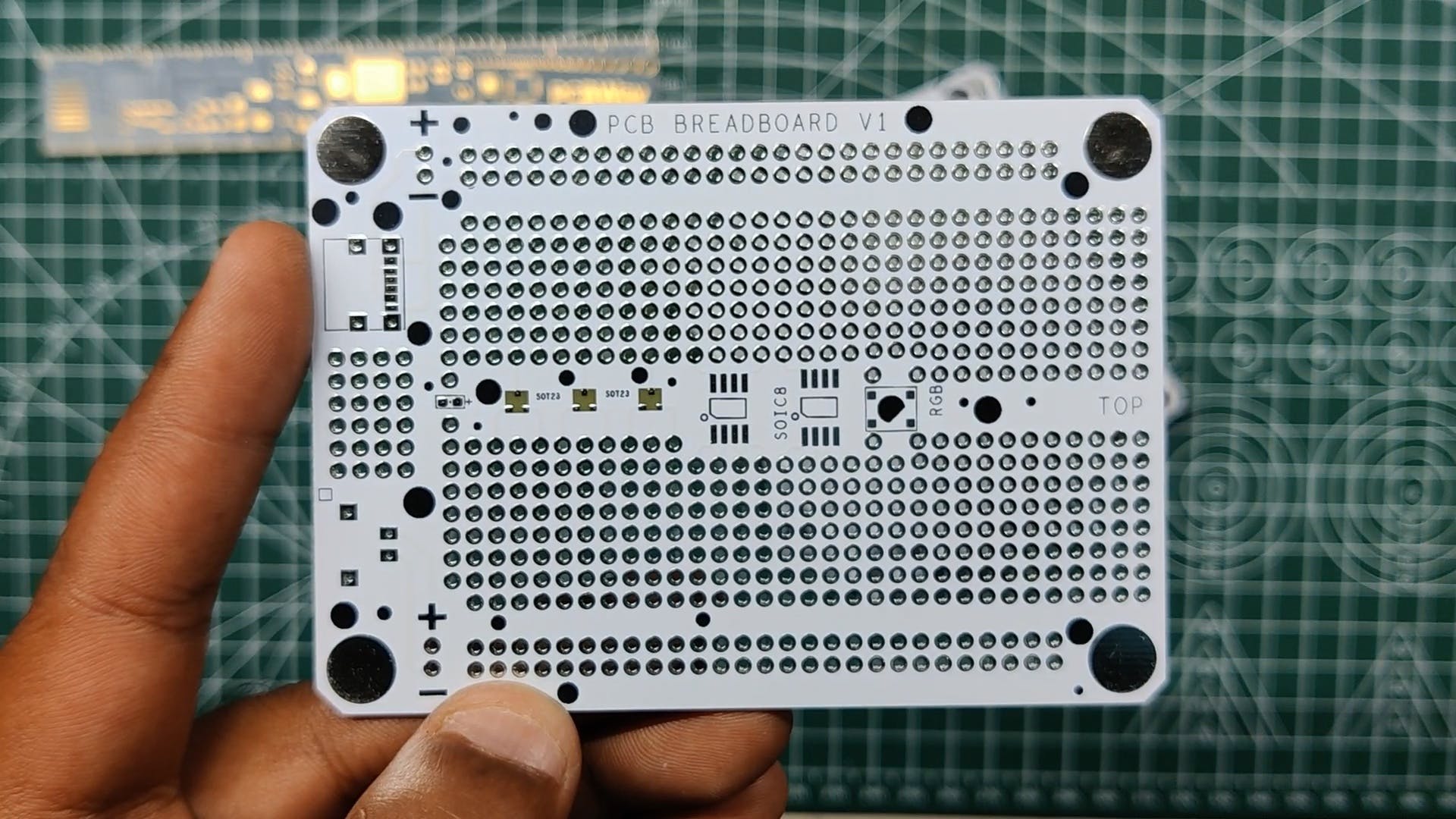
完成面包板设置后,我们为该项目准备主 PCB,该项目将在定制 PCB 面包板上制作。
PCB 面包板是我为快速原型工作而开发的定制板。它由与普通面包板相同的形状因子排列的孔组成。
每个孔距每个孔 2.54 毫米,就像物理面包板和插头引脚中的一样。
PCBWAY 制造了这个,它的质量非常好。
继电器模块
这是控制交流甚至直流负载的主要工作的组件,即 6 通道继电器模块。
6路继电器输出模块触点容量为10A 250V,因此可以处理2500W阈值以下的任何负载。
输入使用 LOW 信号工作并打开继电器,使用 HIGH 信号关闭继电器。
它包含 6 个红色 LED,每个 LED 都与一个光耦合器连接,该光耦合器控制 N 沟道晶体管的栅极,该晶体管然后打开或关闭继电器。
每个继电器都与相同的设置连接,该设置由一个光耦和控制继电器的晶体管组成。
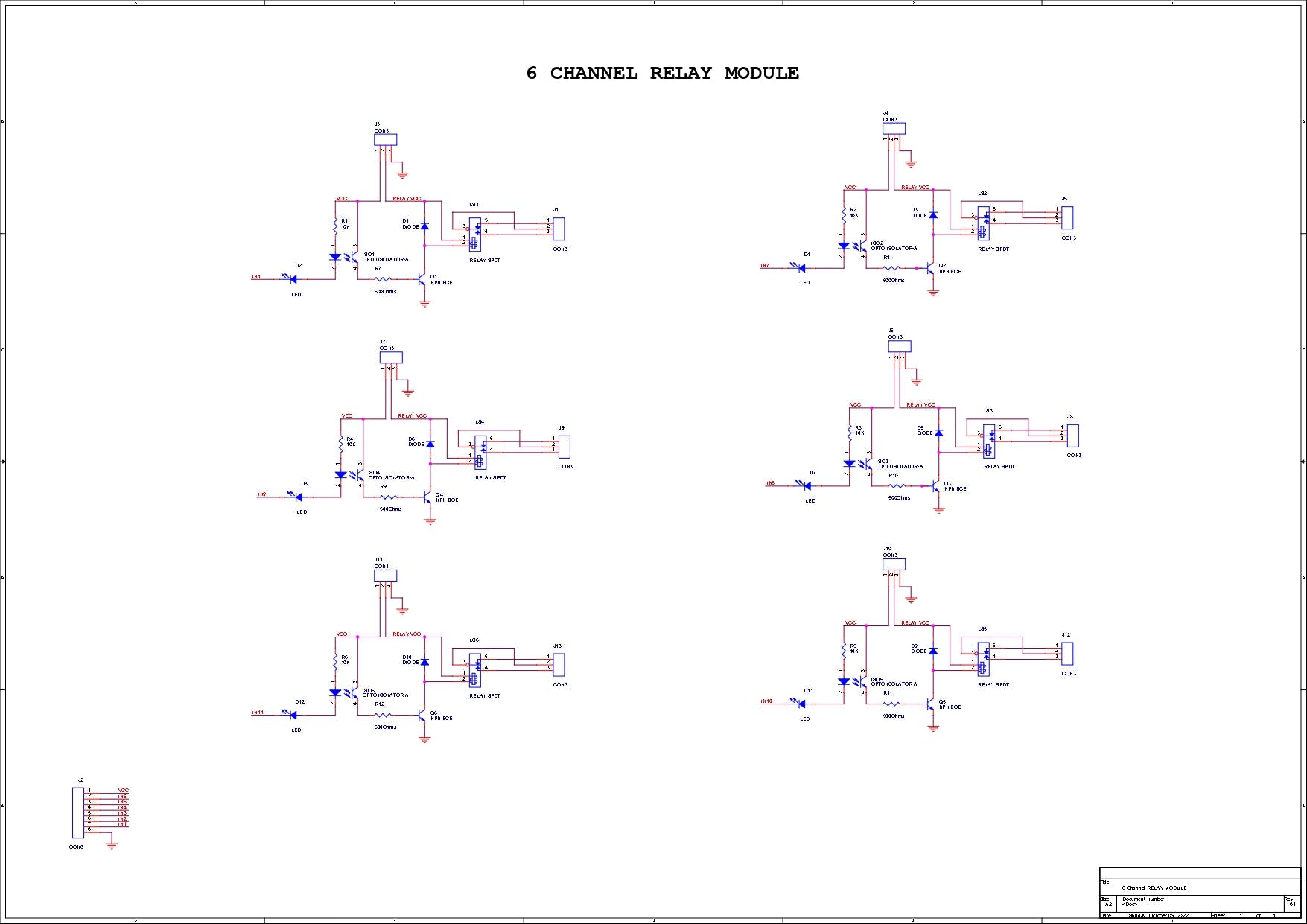
我已经在万用表的帮助下按照轨迹为这个继电器模块创建了一个示意图,您可以使用这个示意图来重新制作您的继电器模块。
PCBWAY礼品店
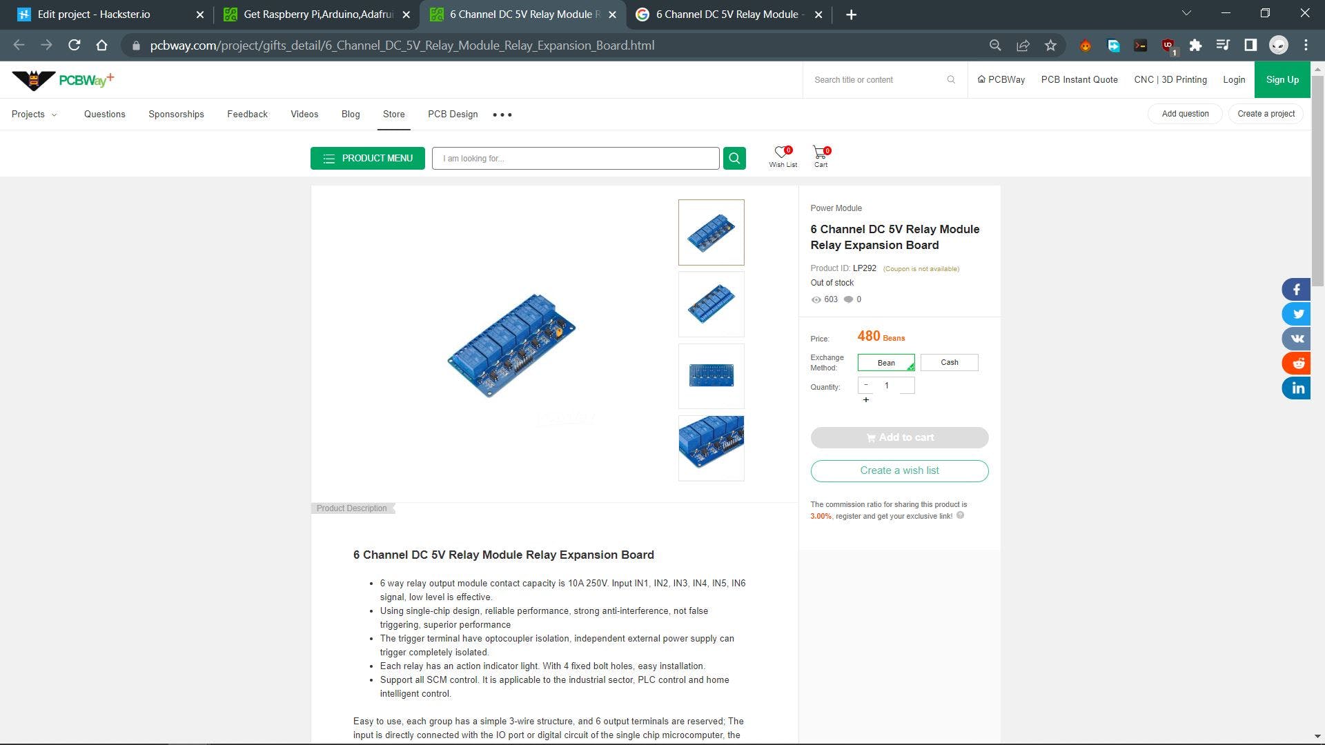
至于采购继电器模块,我使用PCBWAY 的礼品店订购传感器。
https://www.pcbway.com/project/gifts_detail/6_Channel_DC_5V_Relay_Module_Relay_Expansion_Board.html
除了 PCB Services,PCBWAY 也有专门的元件商店。
PCBWAY GIFTSHOP 是一个在线市场,我们可以从中采购所有主要的电子产品,如 Arduino 板、Raspberry Pi 板、模块、传感器等。
PCBWAY 有这个系统,可以让我们通过豆子从他们的礼品店购买任何东西,豆子就像一种可兑换的货币或优惠券,我们通过在 PCBWAY 上下订单或在社区中分享您的项目来获得豆子。
从这里检查 PCBWAY 以获得出色的 PCB 服务 - https://www.pcbway.com/
最终示意图
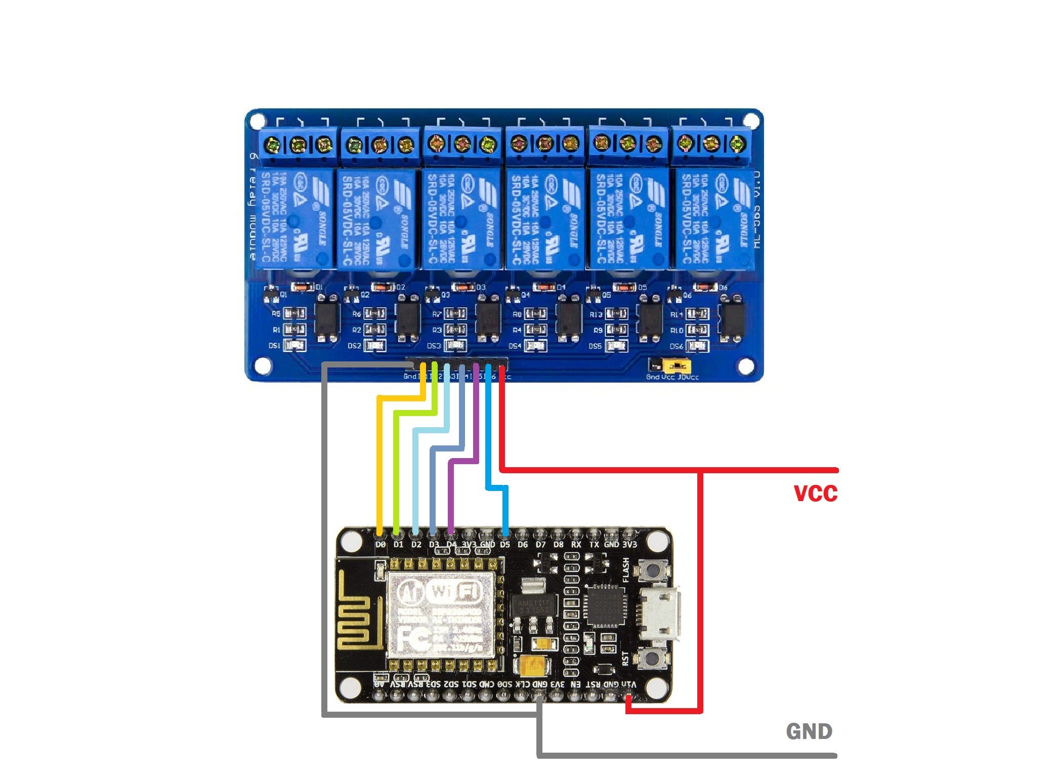
这是连接 ESP8266 NodeMCU 板和 6 通道继电器模块的示意图。
- ESP8266 的 D0 引脚与 Relay 的 IN1 引脚相连。
- D1 与 IN2 相连
- D2与IN3相连
- D3与IN4相连
- D4与IN5相连
- D5与IN6相连
- VCC 或 USB IN 电压与 Relay Module 的 VCC 和 NodeMCU Board 的 Vin 相连。
- 地到地
主要组件
- 我们首先将母头针连接器添加到 ESP8266 板上并切割它以使其适合两侧,然后我对继电器模块执行相同的过程来开始主组件。这里的目标不是直接将 nodemcu 的头针和继电器与面包板焊接,使用头针,以便稍后我们可以将它们都移除并重新使用电路板。
- 接下来,我们将继电器模块和 NODEMCU 放置在 PCB 面包板上
- 我们还在 PCB 面包板的一侧添加了一个 USB 端口,用于将外部电源连接到 NODEMCU 和 RELAY MODULE。
- 然后我们将所有组件焊接到面包板上。
将 IO 引脚与继电器模块连接
- 接下来,我们使用银铜线将ESP8266 Board的每个IO Pin与nodemcu Board的IO Pin连接起来。
- 我们在 GPIO 引脚附近添加铜线,然后将其焊接到位,接下来我们在前一条铜线的末端添加另一根铜线,并与继电器模块的 IO 引脚连接。
- 我们为所有 GPIO 执行此操作
- 对于一些连接,我们添加了电线。
总装
- 完成焊接工作后,我们添加带有继电器模块的 PCB 面包板,电路板现已完成,我们可以继续向其添加主代码。
WEB APP及其主要代码
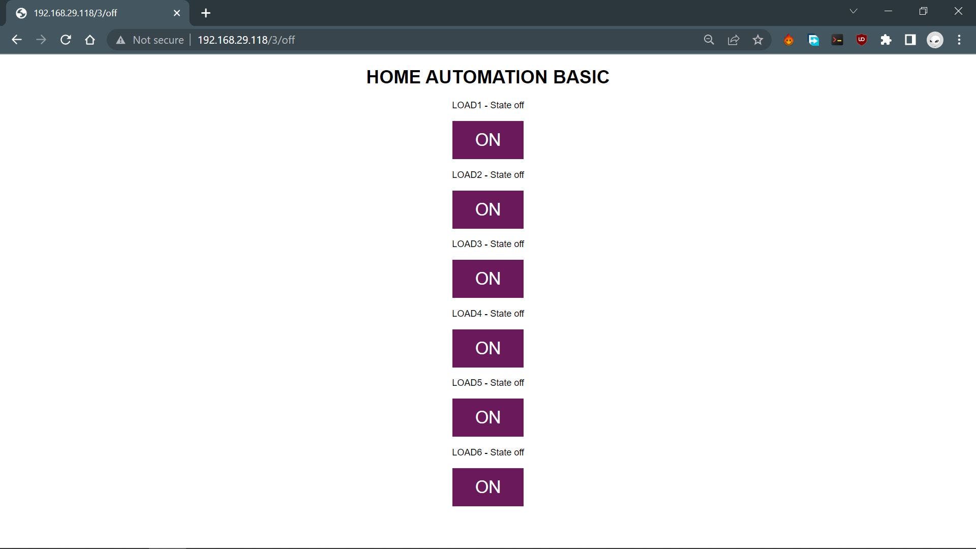
这是用于控制家庭自动化设置的主要 WEB PAGE 或 WEB 应用程序,此网络应用程序是完全定制的,完全由一个草图制成,无需使用任何第三方工具。
#include HOME AUTOMATION BASIC
");
// Display current state, and ON/OFF buttons for OUTPUT1
client.println("LOAD1 - State "
+ output1State + "");
// If the output1State is off, it displays the ON button
if (output1State=="off") {
client.println("");
} else {
client.println("");
}
// Display current state, and ON/OFF buttons for OUTPUT2
client.println("LOAD2 - State "
+ output2State + "");
// If the output2State is off, it displays the ON button
if (output2State=="off") {
client.println("");
} else {
client.println("");
}
// Display current state, and ON/OFF buttons for OUTPUT3
client.println("LOAD3 - State "
+ output3State + "");
// If the output3State is off, it displays the ON button
if (output3State=="off") {
client.println("");
} else {
client.println("");
}
// Display current state, and ON/OFF buttons for OUTPUT4
client.println("LOAD4 - State "
+ output4State + "");
// If the output4State is off, it displays the ON button
if (output4State=="off") {
client.println("");
} else {
client.println("");
}
// Display current state, and ON/OFF buttons for OUTPUT5
client.println("LOAD5 - State "
+ output4State + "");
// If the output5State is off, it displays the ON button
if (output5State=="off") {
client.println("");
} else {
client.println("");
}
client.println("");
// The HTTP response ends with another blank line
client.println();
// Break out of the while loop
break;
} else { // if you got a newline, then clear currentLine
currentLine = "";
}
} else if (c != '\r') { // if you got anything else but a carriage return character,
currentLine += c; // add it to the end of the currentLine
}
}
}
// Clear the header variable
header = "";
// Close the connection
client.stop();
Serial.println("Client disconnected.");
Serial.println("");
}
}
这是我在此设置中使用的代码,它是一个简单的基于 WEB 服务器的草图,可让我们使用 WEB APP 控制五个 GPIO。
这个 Sketch 融合了经典的嵌入式 C 语言和带有一点 CSS 的 HTML。
我们通过以下几行在此草图中设置了 HTML 页面。
// Display the HTML web page
            client.println("html><html>");
            client.println("<head><meta name=\"viewport\" content=\"width=device-width, initial-scale=1\">");
            client.println("<link rel=\"icon\" href=\"data:,\">");
            client.println("<style>html { font-family: Helvetica; display: inline-block; margin: 0px auto; text-align: center;}");
            client.println(".button { background-color: #6a195b; border: none; color: white; padding: 16px 40px;");
            client.println("text-decoration: none; font-size: 30px; margin: 2px; cursor: pointer;}");
            client.println(".button2 {background-color: #a82890;}style>head>");

            // Web Page Heading
            client.println("<body><h1>HOME AUTOMATION BASICh1>");
这个草图比较容易理解,我们有 5 个输出,它们在草图开始时声明并设置为 LOW 状态。
const int output1 = 16; //D0
const int output2 = 5;  //D1
const int output3 = 4;  //D2
const int output4 = 0;  //D3
const int output5 = 2;  //D4
digitalWrite(output1, LOW);
  digitalWrite(output2, LOW);
  digitalWrite(output3, LOW);
  digitalWrite(output4, LOW);
  digitalWrite(output5, LOW);
当按下 HTML 按钮时,每个 GPIO 都由下面的行触发。
// turns the GPIOs on and off
            if (header.indexOf("GET /1/on") >= 0) {         //LOAD1
              Serial.println("LOAD1 on");
              output1State = "on";
              digitalWrite(output1, HIGH);
            } else if (header.indexOf("GET /1/off") >= 0) {
              Serial.println("LOAD1 off");
              output1State = "off";
              digitalWrite(output1, LOW);
请注意,此设置仅适用于 ESP8266 和您在同一网络上浏览 APP 的设备。(本地网络运营)
结果
这是结果,如您所见,该系统正在运行。
每当我们通过 WEB APP 切换继电器时,每个继电器模块顶部都有一个 LED 指示灯会打开和关闭。
交流负载测试
在开始进行此设置之前,请确保佩戴适当的绝缘橡胶手套,并在插入交流电源后尽量不要触摸交流侧。
- 我们按照上述接线方案将交流灯泡座与继电器的公共和 NC 连接器以及交流电源接线连接起来。
- 接下来,我们打开 WEB APP 并切换连接到交流电源的负载 1。
总结与改进
此设置有效,现在我们可以将其添加到我们家中的 MCB 盒中,以控制特定区域或任何控制至少 6 个光输出的照明开关附近。
它的工作方式也很简单,继电器就像物理开关,我们可以将它们与任何光源或输出串联添加。通过将 RELAY 的状态更改为 HIGH 或 LOW,它可以断开或连接电路并控制与其连接的负载。
此设置使用带有外部 5V 电源的 NodeMCU 板。
理想情况下,板载 240V AC 至 5V 1A DC 转换器以及通过单线轻松连接的负载输出。NodeMCU 可以替换为基于最小 ESP12F 的设置,该设置将在相同的拓扑中实现自己的继电器模块板。这就是我将在这个项目的第 2 版中做的事情。
这就是今天的内容,如果您在设置此项目时遇到任何问题,请发表评论。
特别感谢 PCBWAY 提供了我在这个项目中使用的组件,检查它们以获得各种 PCB 或 PCBA 相关的服务以降低成本。
谢谢,我很快就会带着一个新项目回来。
声明:本文内容及配图由入驻作者撰写或者入驻合作网站授权转载。文章观点仅代表作者本人,不代表电子发烧友网立场。文章及其配图仅供工程师学习之用,如有内容侵权或者其他违规问题,请联系本站处理。 举报投诉
- 相关下载
- 相关文章


