
资料下载


在Proteus中模拟SD卡模块
王凯
分享资料个
描述
在本主题中,我们将讨论如何开始使用 Arduino 和 SD 卡(microSD 卡)的简单 proteus 模拟。
我将在本主题的后面部分解释如何阅读有关 SD 卡的信息,以使您熟悉该概念。在本例中,我们将学习如何使用winimage软件创建映像文件,并使用winimage和SD 库选择某些参数,如卷类型、可用空间和其他信息,并通过串行端口发送。然后我们将模仿 proteus 中的示例,以达到类似于实际实验的最佳所需结果。
Arduino 的 SD 卡库非常出色,它使与 SD 卡的交互非常简单。使用 Arduino SD 库可以读取和写入 SD 卡。它基于 William Greiman 的 sdfatlib。在普通 SD 和 SDHC 卡上,该库支持 FAT16 和 FAT32 文件系统。对于文件名,它使用 8.3 短名称。
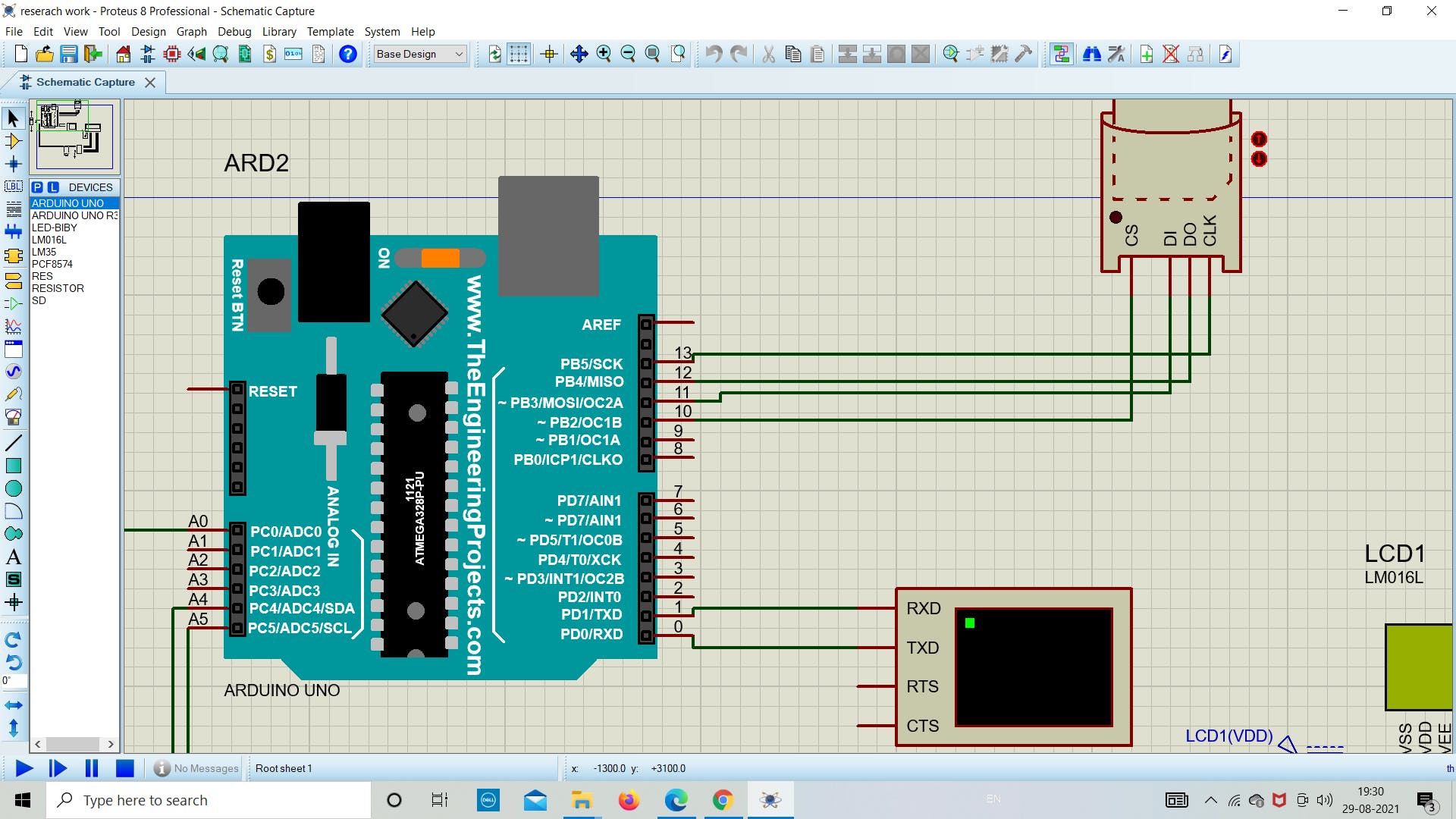
SPI 用于在微控制器和 SD 卡之间进行通信,它位于数字引脚 11、12 和 13(在大多数 Arduino 板上)或 50、51 和 52(在某些 Arduino 板上)(Arduino Mega)。还需要第二个引脚来选择 SD 卡。可以使用硬件 SS 引脚(大多数 Arduino 板上的引脚 10 或 Mega 上的引脚 53)或 SD.begin() 调用中指定的另一个引脚。
所需组件
硬件
- Arduino板
- 具有 FAT16 或 FAT32 文件系统的 SD 卡
- LM35
- 虚拟终端(作为串行监视器)
- PCF8574 I2C液晶接口模块
- LM016L (LCD) 显示器
- R1 & R2 = 10k 欧姆
软件
- 变形虫
- Arduino IDE
- Winimage
1.先决条件练习
在我们开始进行实际零件仿真之前,我们将通过简单的下载、安装和设置 Arduino IDE 和 Proteus 库的练习来热身。
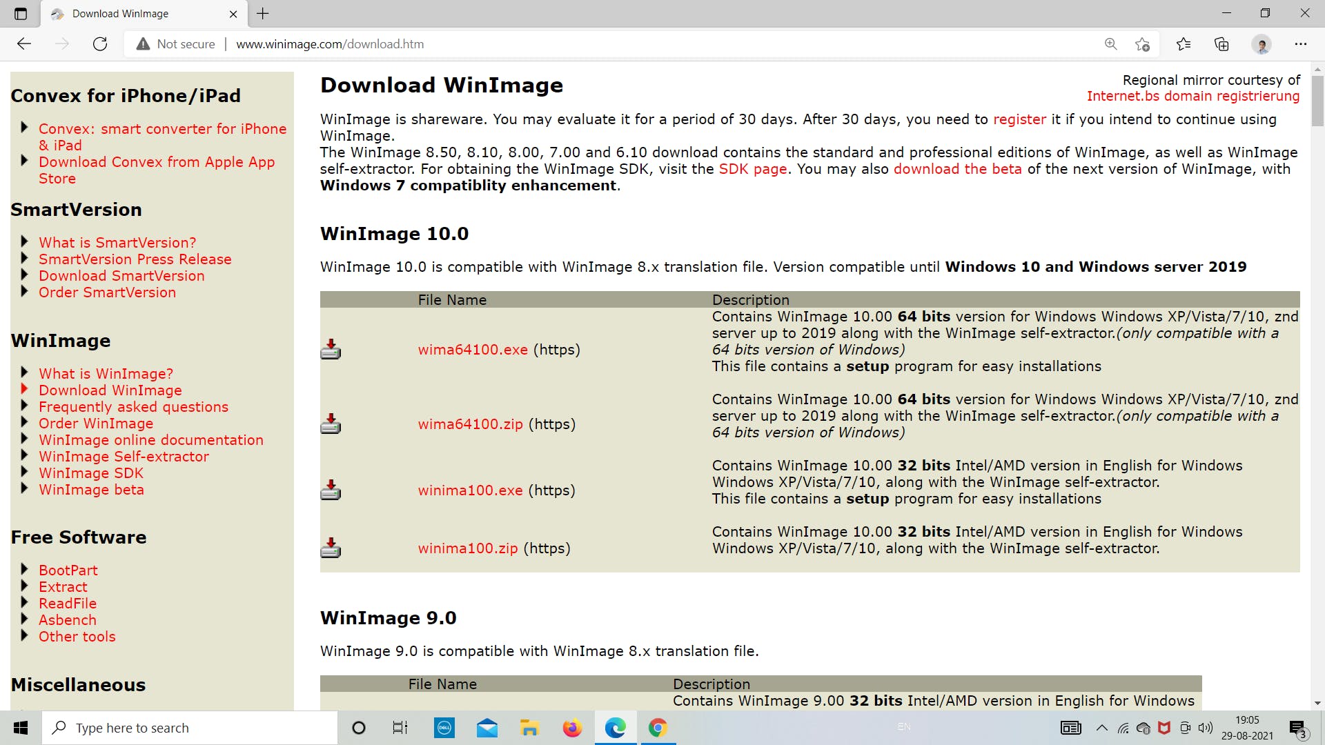
一世。安装 Winimage
我们的第一步是从 Internet 下载 winimage 并将下载路径设置为便于以后访问。根据系统要求,从官网选择相应的 latest.exe 文件。
一世。在 IDE 中添加 SD 卡库
现在我们将从 IDE 下载 SD 库。请按照下图所示的步骤了解有关如何下载适用于 Arduino IDE 的 SD 库的更多信息。我们将使用这个库来为 Arduino 编程 SD 卡模块以存储和检索数据。
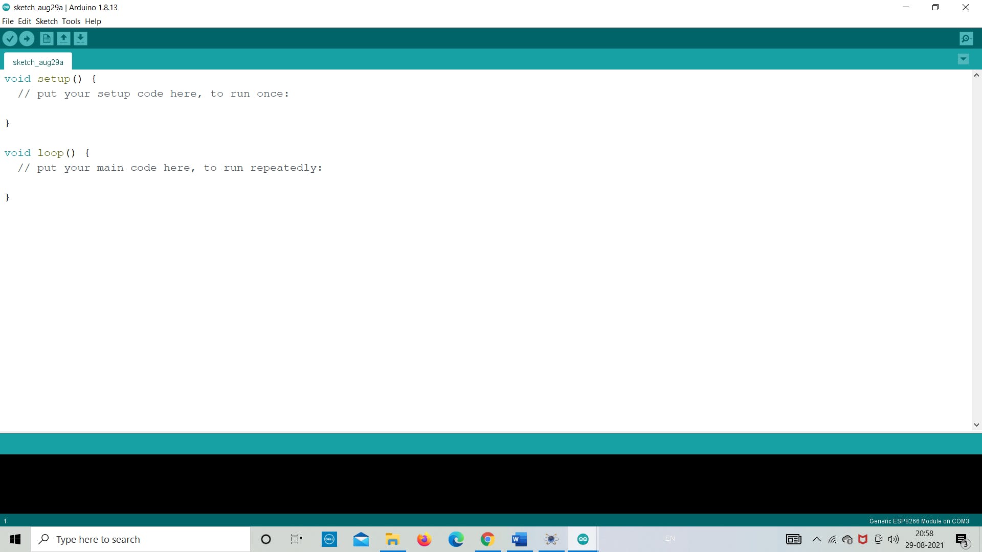
第 1 步:打开 Arduino IDE
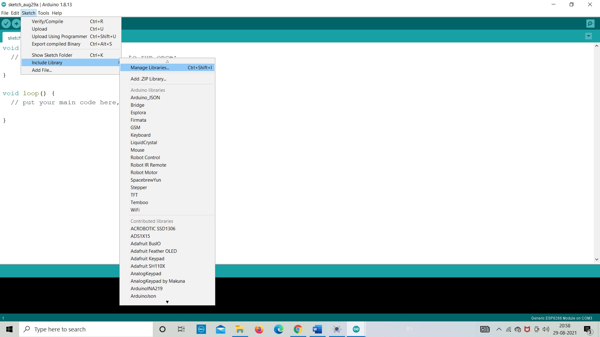
第 2 步:转到“草图”>>“包含库”>>“管理库”
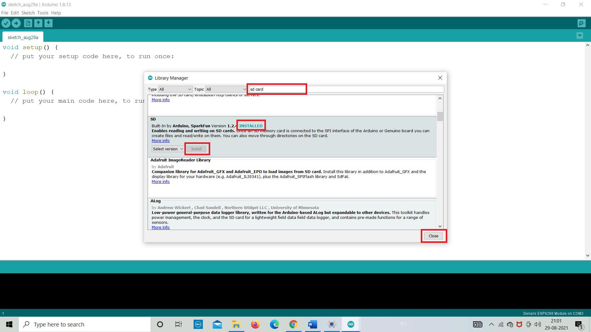
第 3 步:在搜索栏中搜索“SD”并从那里“安装”
ii. 创建 Winimage 映像文件
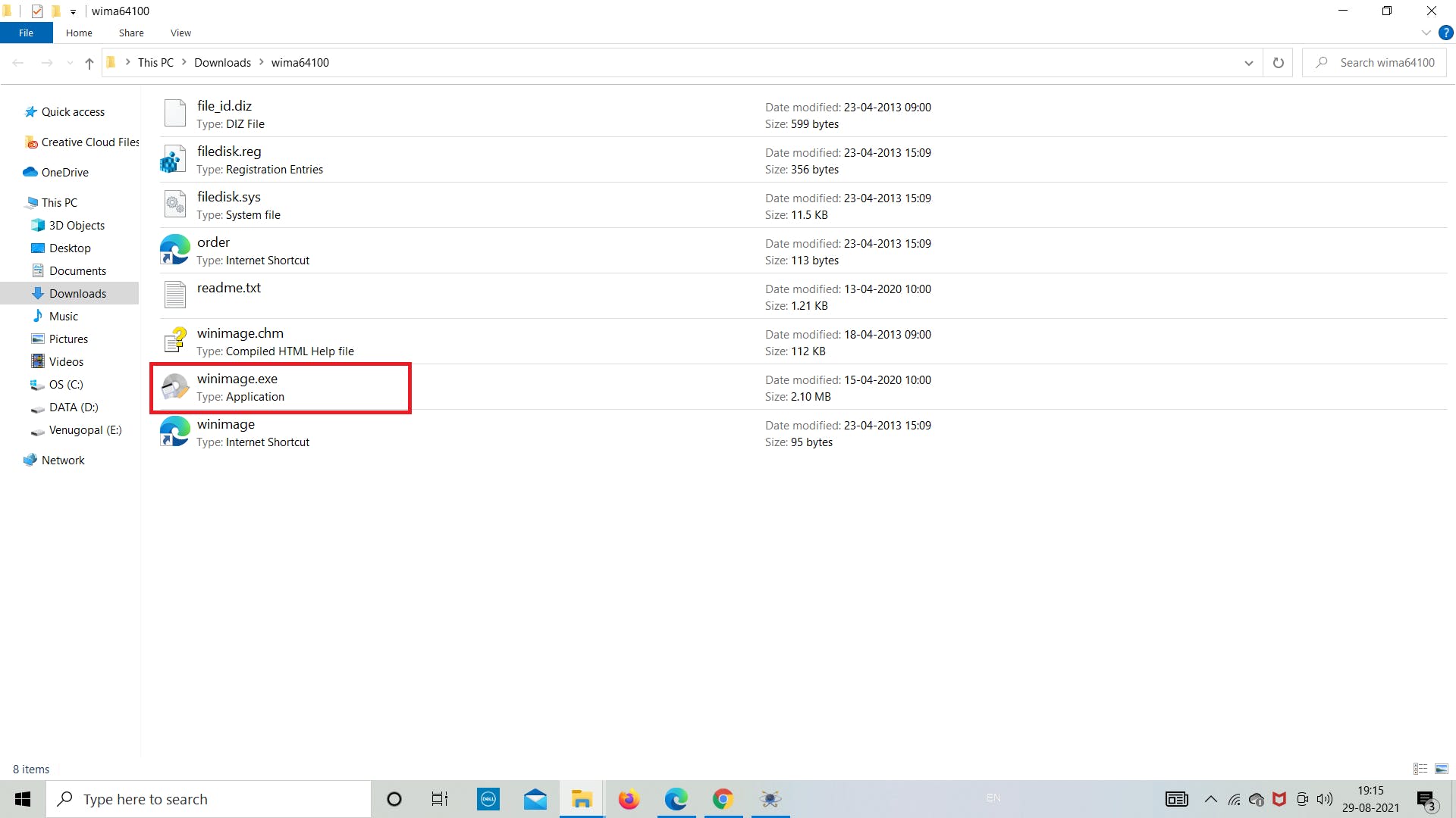
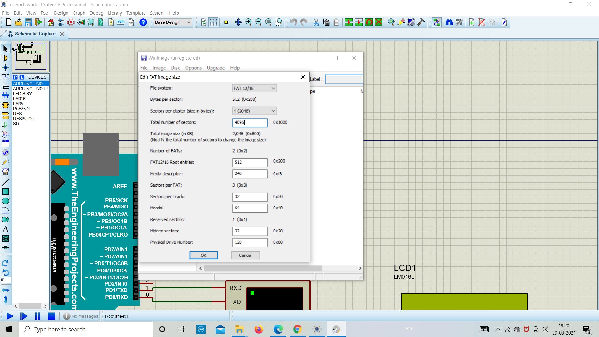
下一步是使用 winimge.exe 软件创建图像文件。在这里,我们将从下载的文件夹中打开它,并将创建 2 MB 大小的文件。该文件将用于将 SD 卡模块中的数据存储为 .txt 格式。
使用 WinImage,您可以在硬盘驱动器或其他媒体上重新创建磁盘映像、查看其内容、提取基于映像的文件、添加新文件和目录、更改格式以及对映像进行碎片整理。
按照下面的图像来了解我们如何创建图像文件。
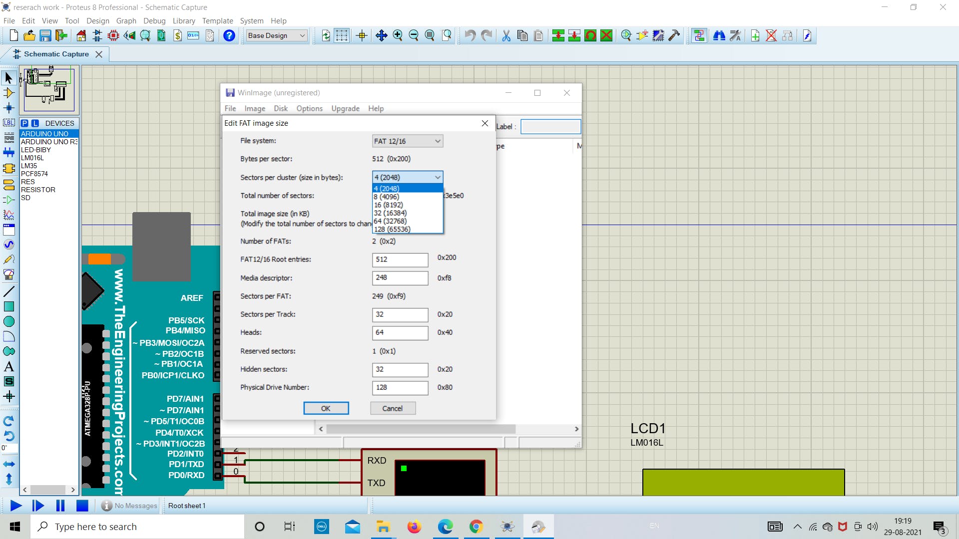
保持 FAT 12/16 和其他参数不受影响,除了图像大小。
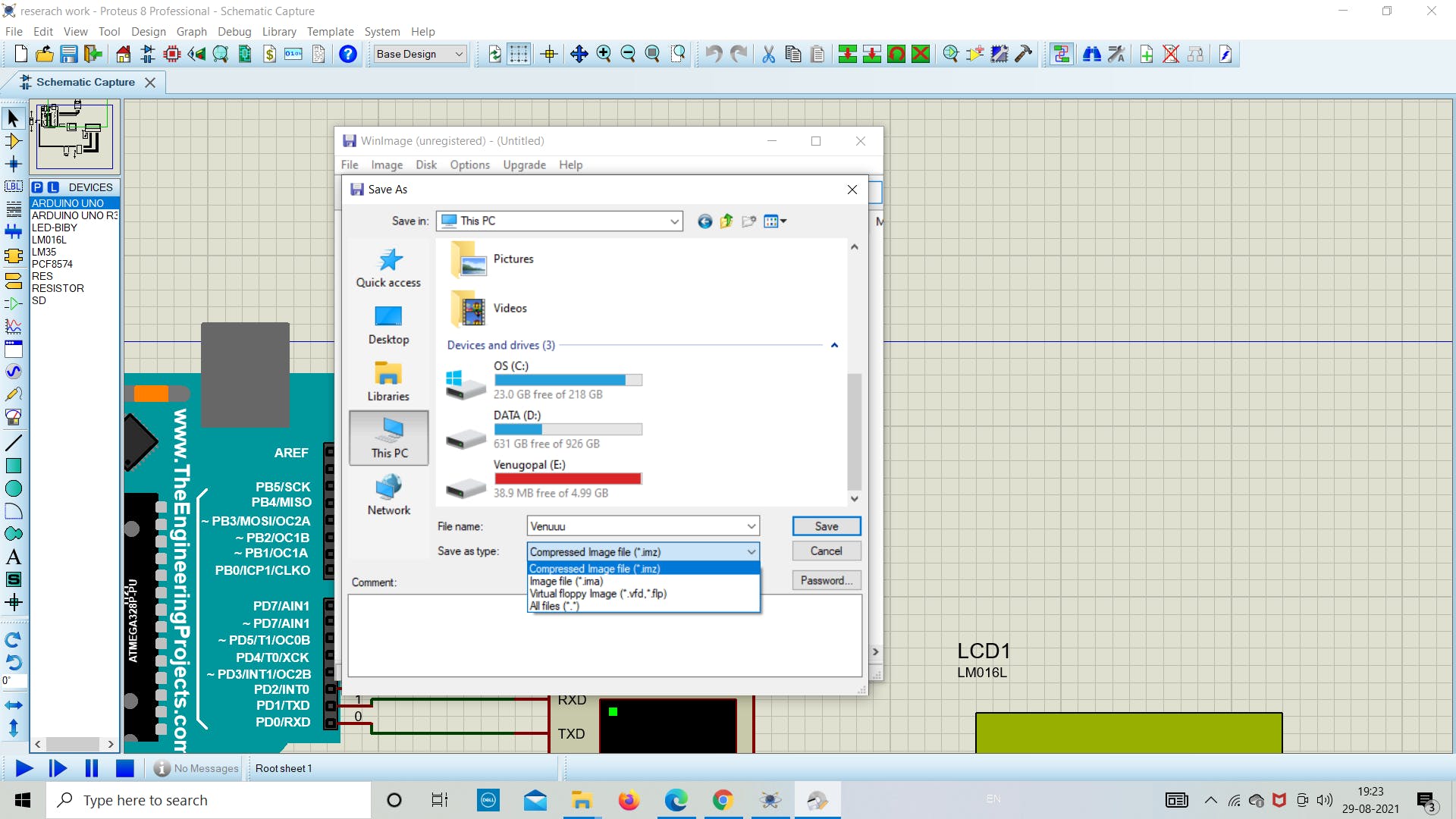
对于这个例子,我们将使用 2 MB 的图像文件,因此创建了相同的图像,如下图所示。我们为图像文件命名为“Venuuu.IMG”
注意:保存文件时不要更改任何扩展名 (*.IMG)。
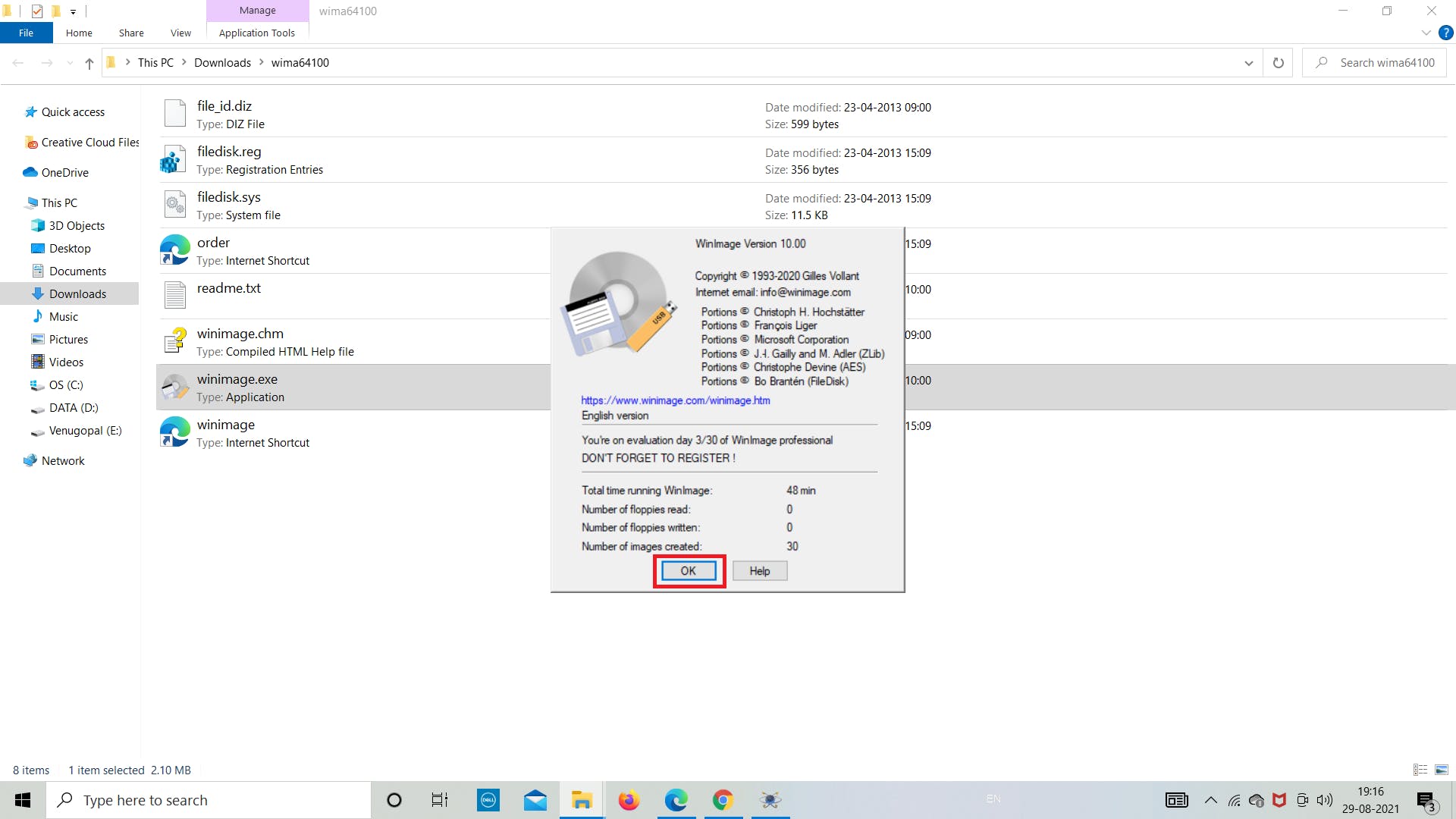
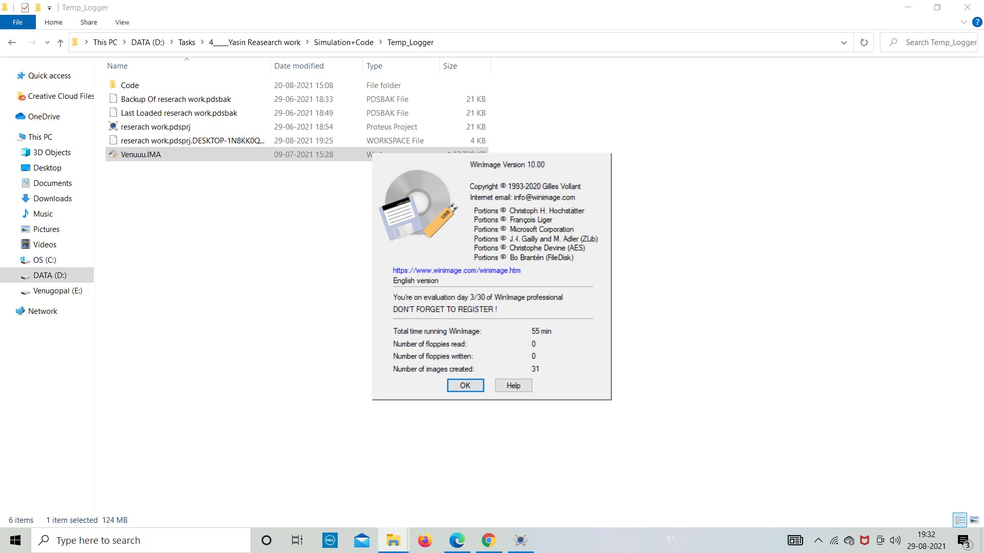
第一步:打开“winimage.exe”文件
第 2 步:单击“确定”并继续
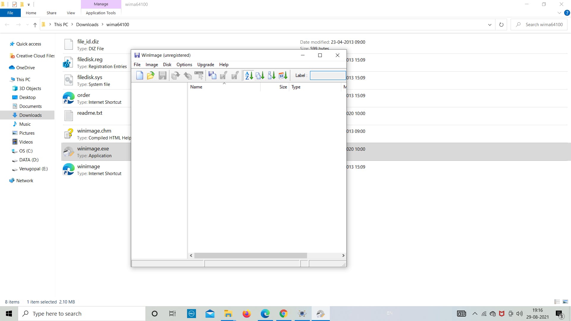
第 3 步:转到左上角的“文件”
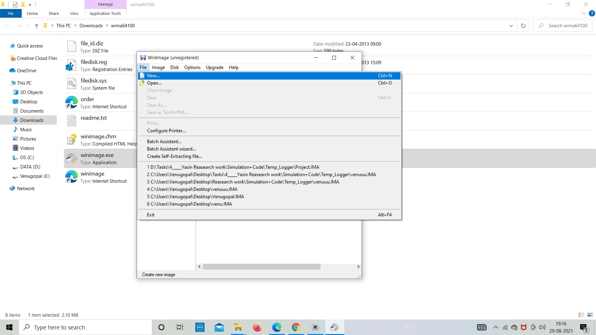
第四步:点击“新建”
第 5 步:点击“选择自定义图像格式”
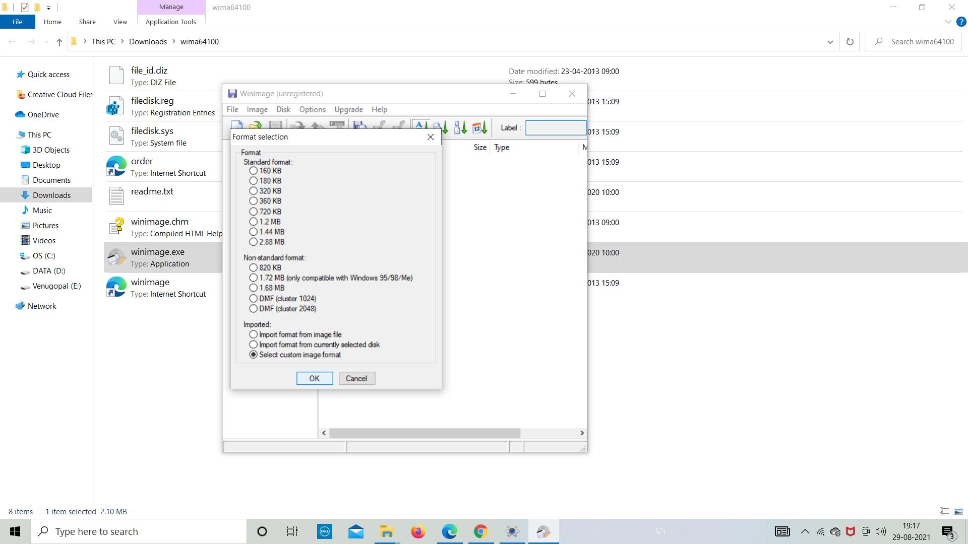
第 6 步:从下拉列表中选择“4 (2048)”
第7步:保持一切原样,然后单击“确定”

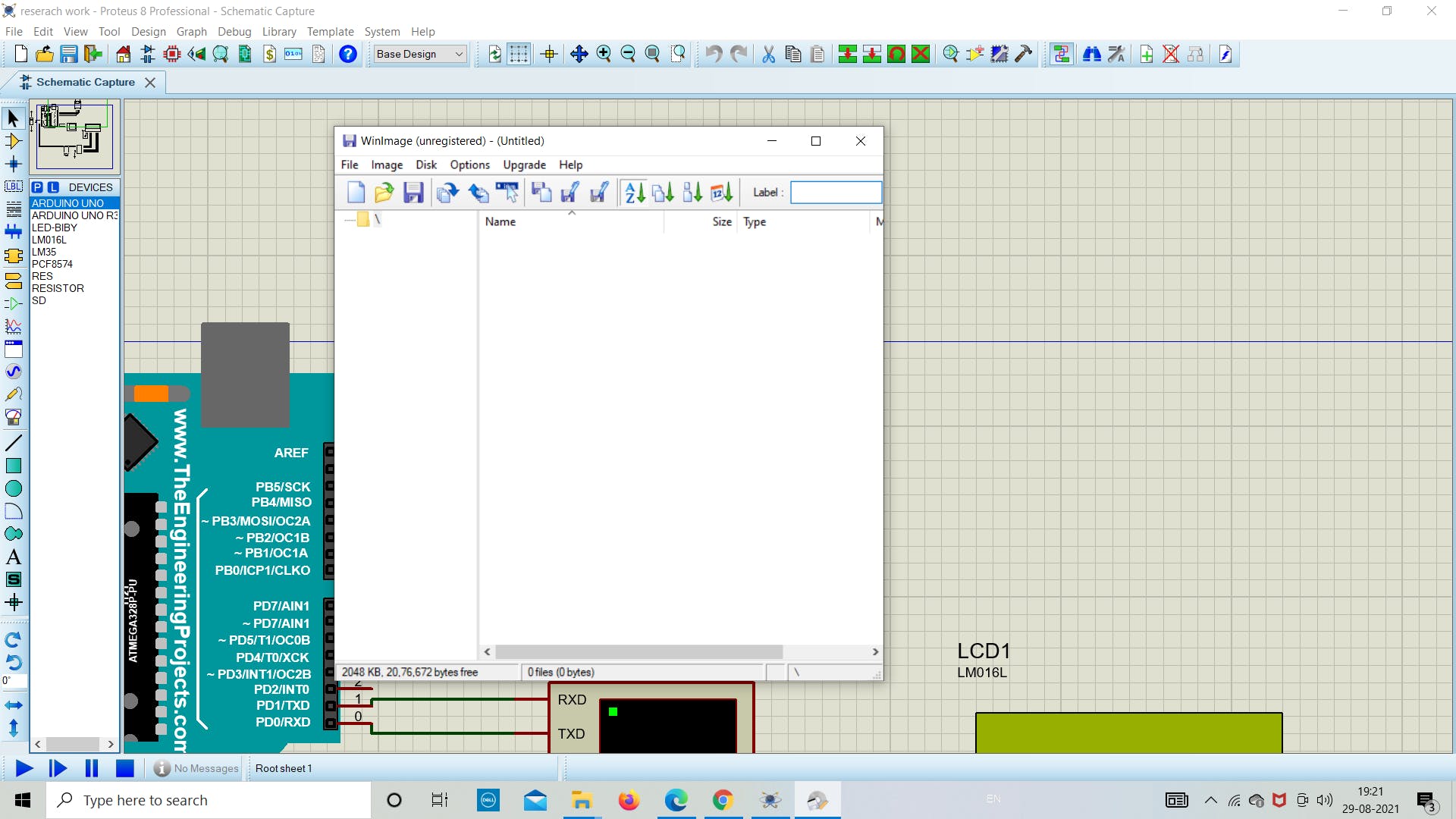
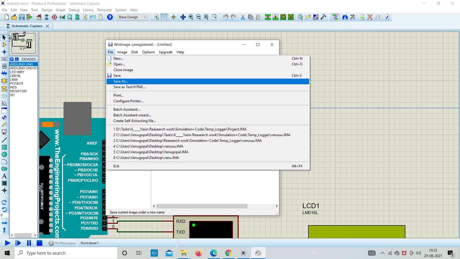
第8步:现在点击“文件”保存文件
第 9 步:现在将文件“另存为”到目标文件夹
1. 模拟与编码
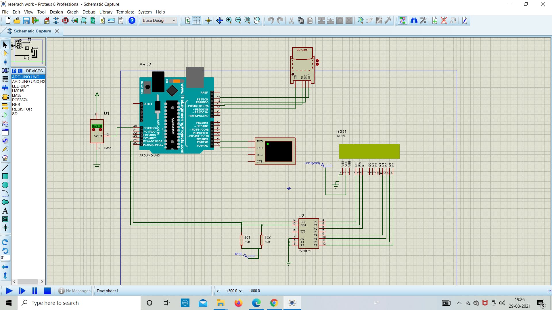
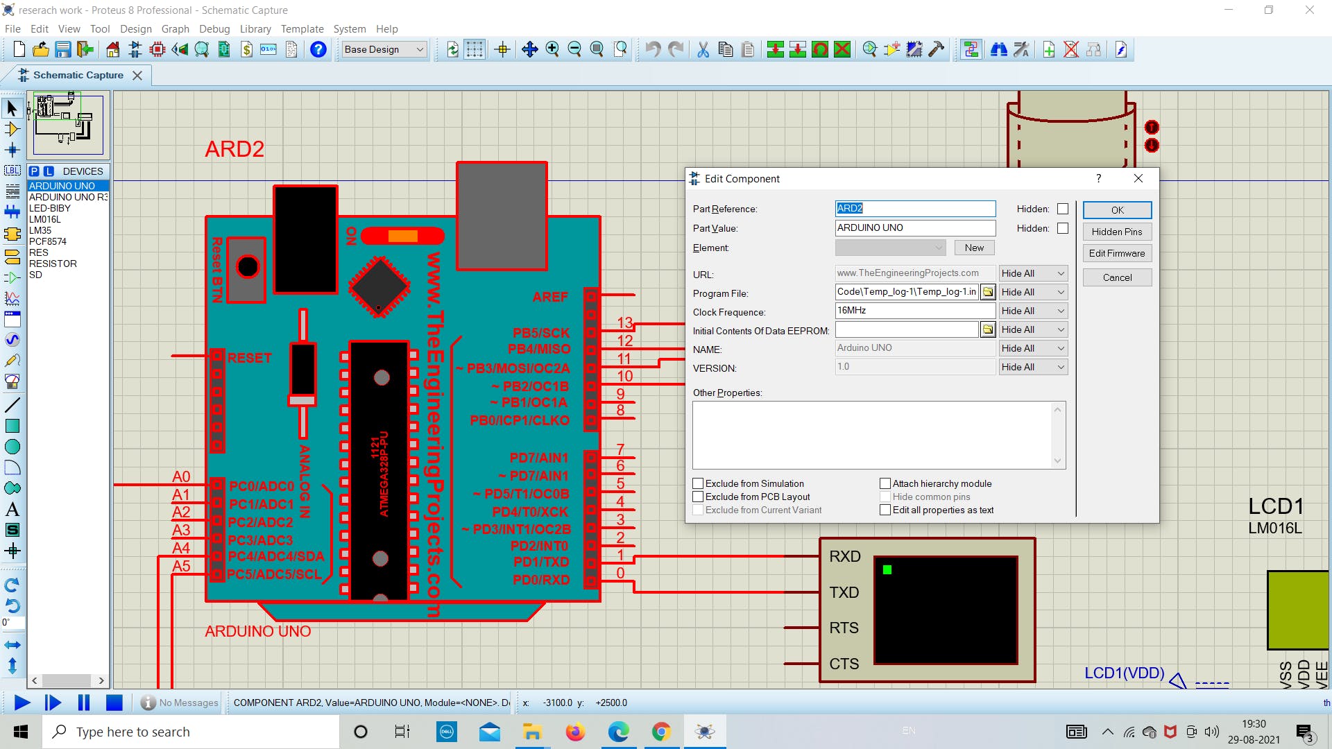
在成功设置了模拟所需的所有先决条件后,现在我们将深入研究在 proteus 中模拟 SD 卡模块的实际部分。现在在 proteus 中打开新文件,然后从软件列表中拖放所需的组件(参考下图),因为我们在上面提到了所有组件的名称。
在这里,我们使用 I2C (PCF8574) 将 LCD 连接到 Arduino,这允许使用较少数量的板上引脚。
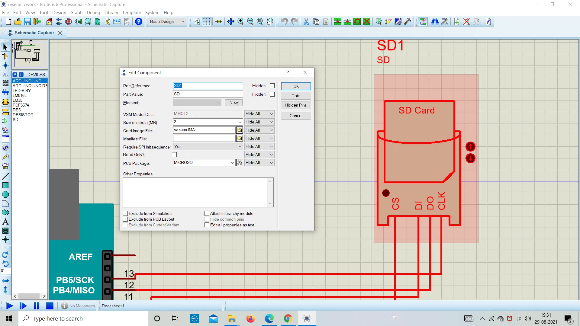
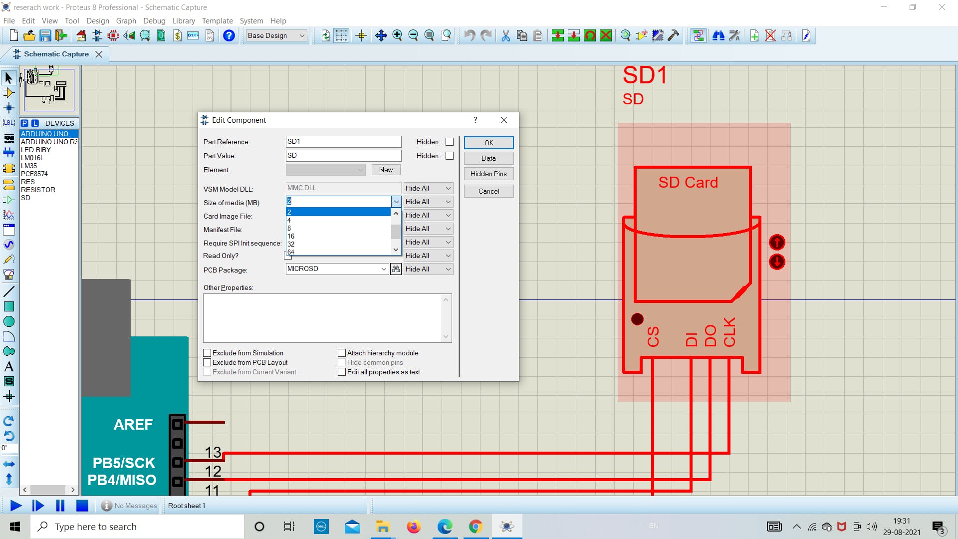
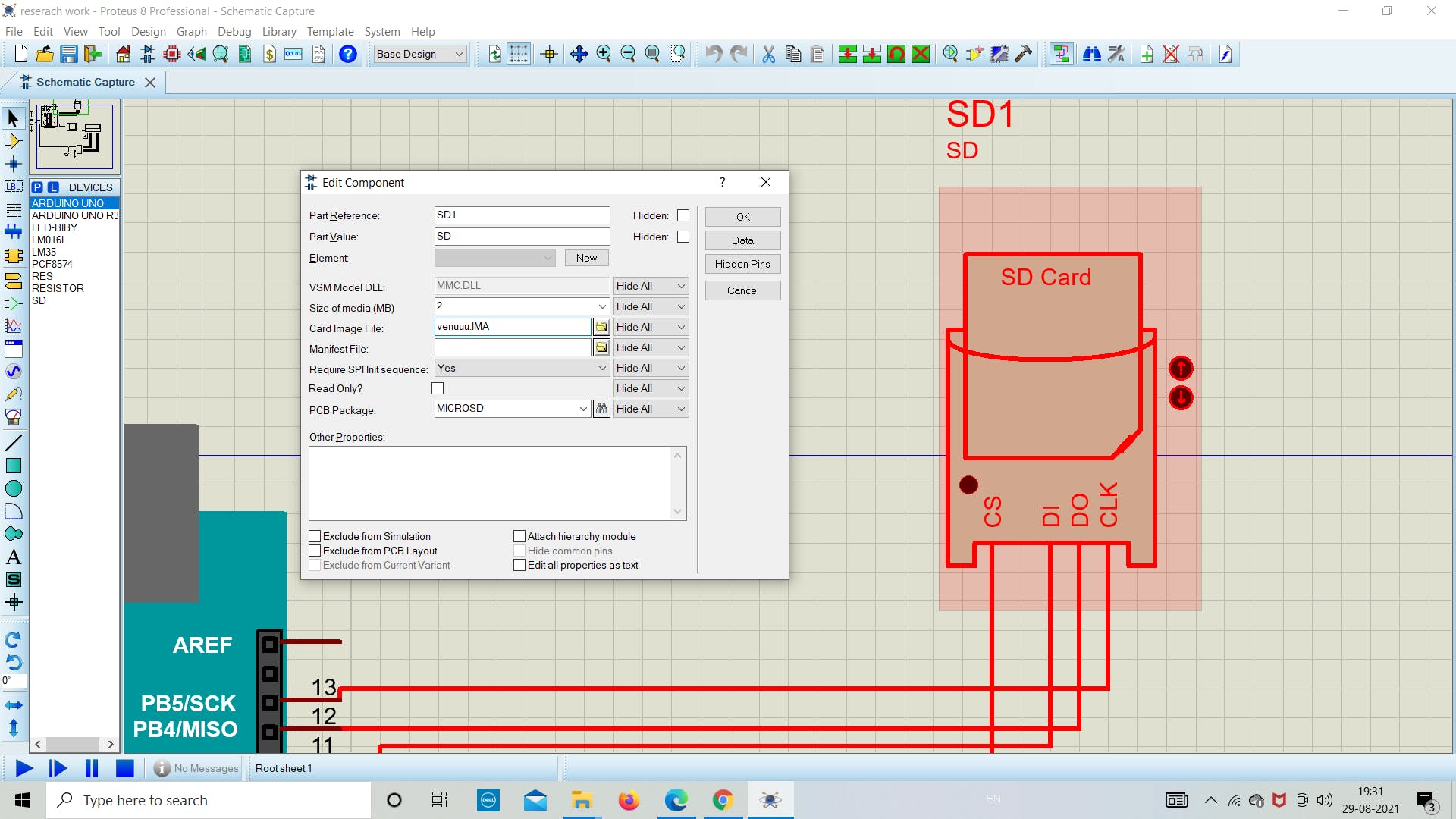
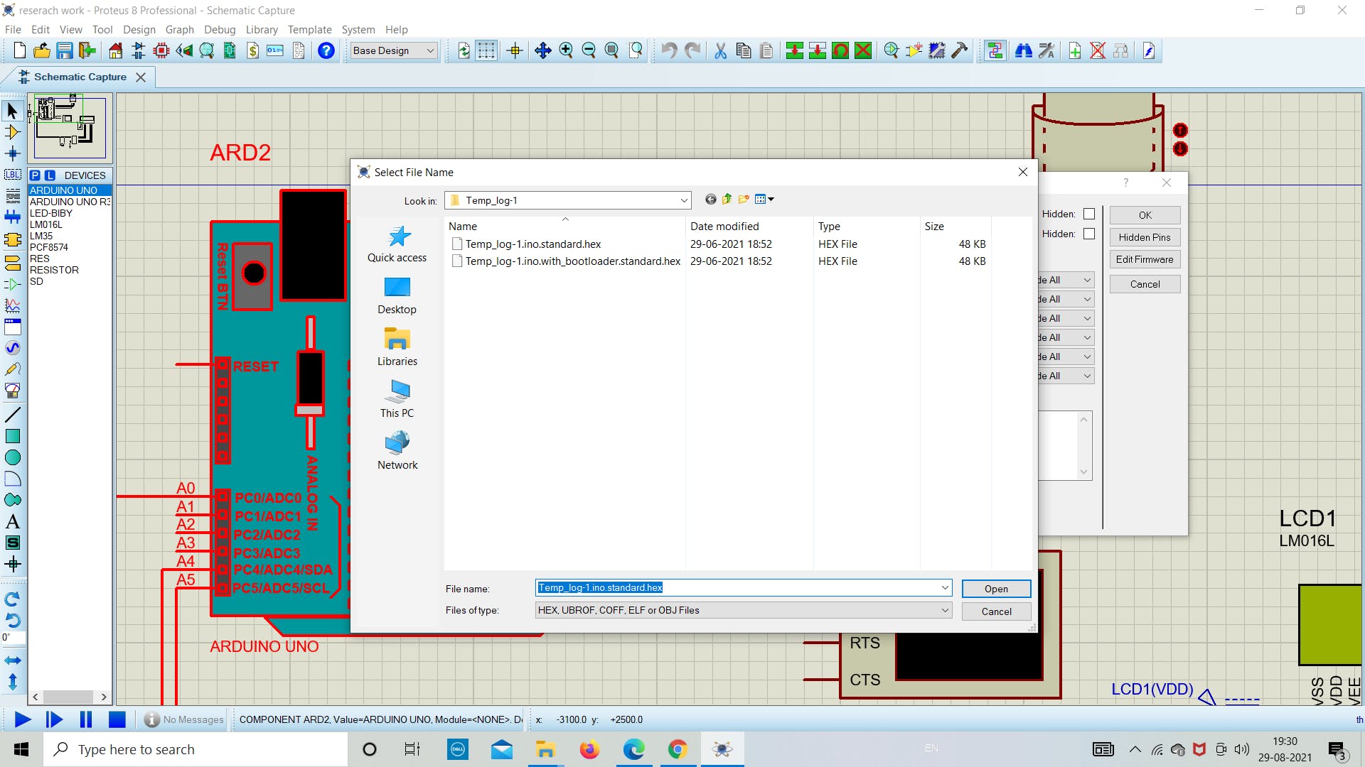
在下一部分中,如下图所示分配 SD 卡模块中图像文件的文件路径,并选择文件大小为 2 MB。
在这个阶段,我们将在 proteus 模拟中的 SD 卡模块中设置卡映像文件路径(下图相同)。
注意:请选择与您创建的图像文件相同的媒体大小(MB)。您可以根据需要创建任何大小的图像文件。
2. 检查 SD 卡的状态
现在我们在 Arduino 中添加下面的草图来了解 SD 卡模块的状态。
下面的草图用于了解我们的 SD 卡是否正确连接到 Arduino。如果没有找出原因并调试它。
上传下面的草图作为成功运行模拟的主要步骤。如果一切顺利,如下图所示,那么您就在正确的轨道上获得最终结果。
// Interfacing Arduino with SD card example (get SD card info)
// include the SD library:
#include
3. 串行监视器输出
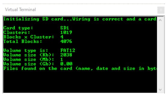
一旦我们在 Arduino 中上传程序,我们将在串行监视器中看到以下任何状态。
1.如果没有卡或Arduino无法连接到它,串口监视器将显示以下消息:
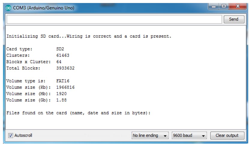
2.如果我们用 FAT16 文件系统放置一个 2 MB 的图像文件,我得到的结果如下所示:
4. 编程、上传和存储
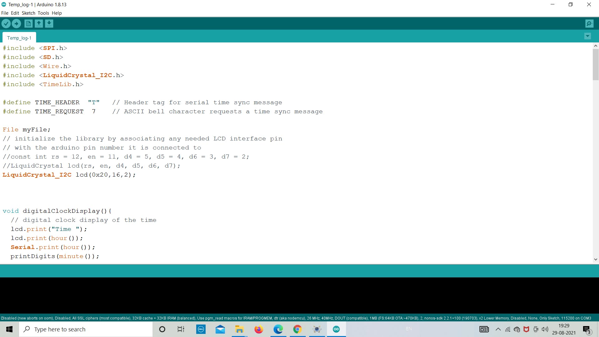
现在我们将生成代码并将其上传到 Arduino,以从 LM35 传感器获取温度值。带有日期和时间的温度值使用 winimage 存储在 .txt 文件中。我们在这里使用 LCD 为用户显示温度,而无需每次打开图像中的 .txt 文件。
将程序保存在所需位置并上传。作为参考,请使用下面的代码了解更多信息。
上传后运行模拟并等待一段时间在 SD 卡中存储 10-20 个读数。
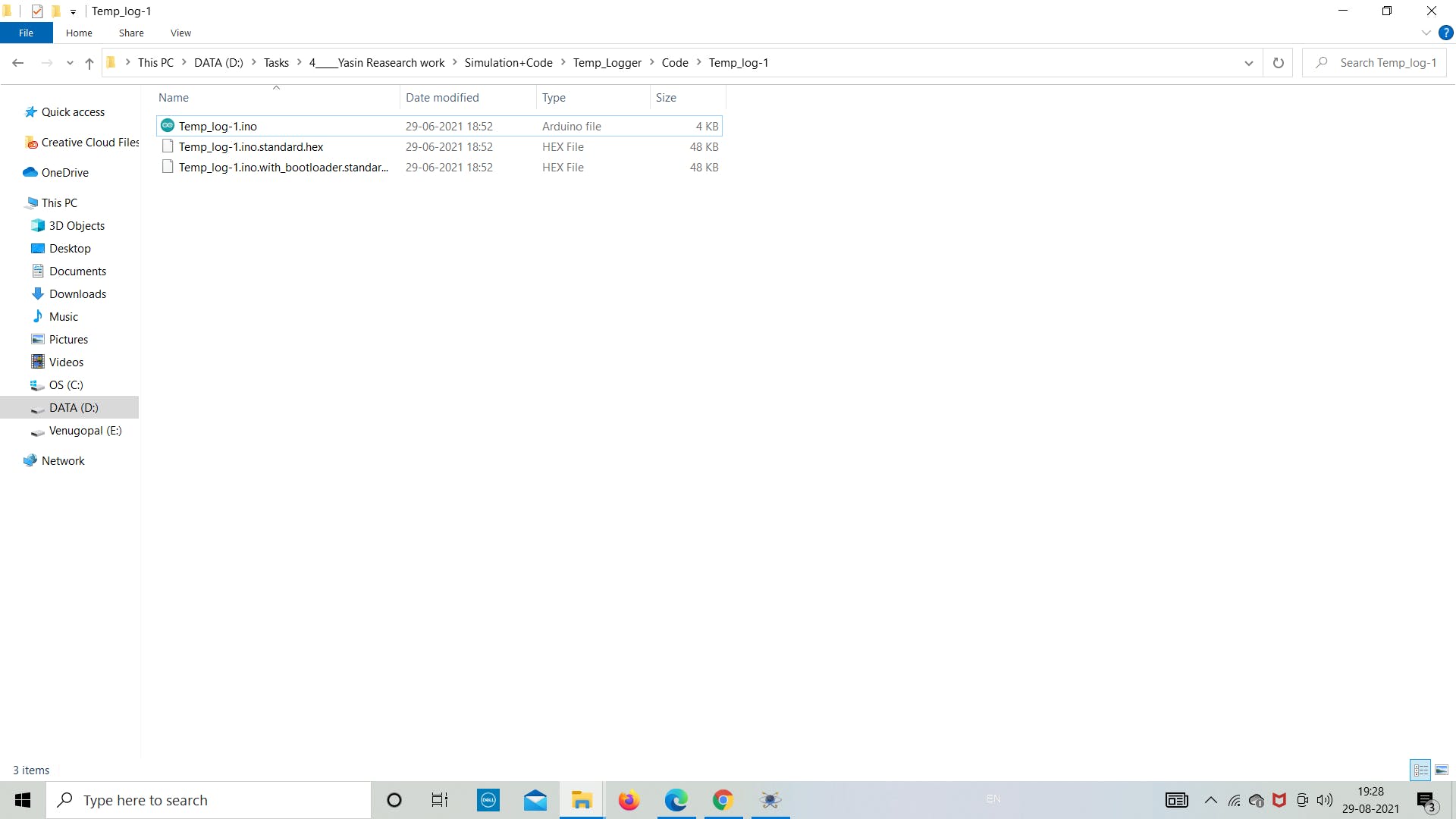
以下是要上传到 Arduino 板的最终草图。参考以下代码并将其保存在目标文件夹中。
#include
5. 导出 SD 卡数据
正如我们在模拟部分所做的那样,现在让我们看看数据是否存储在图像文件中。
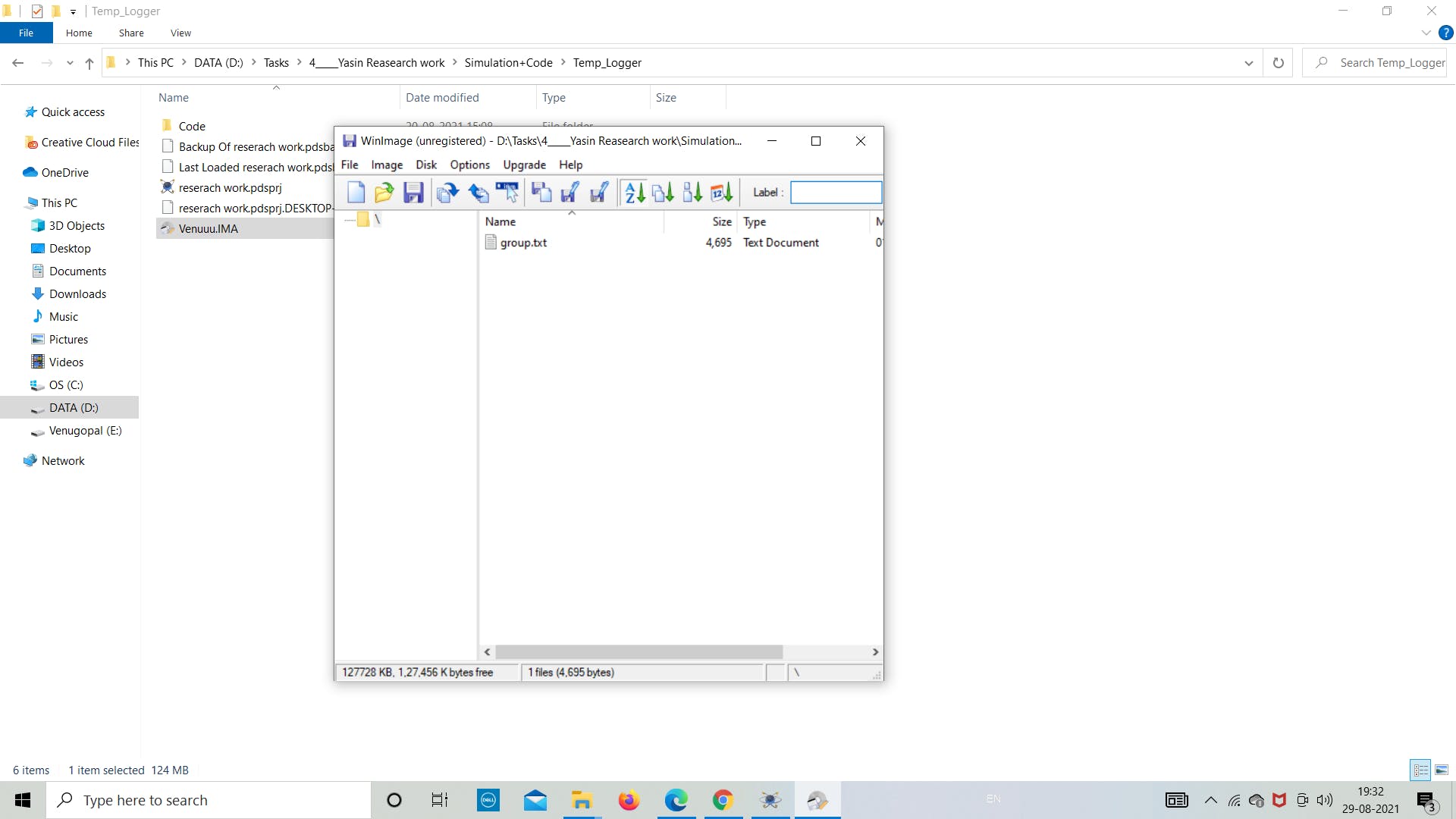
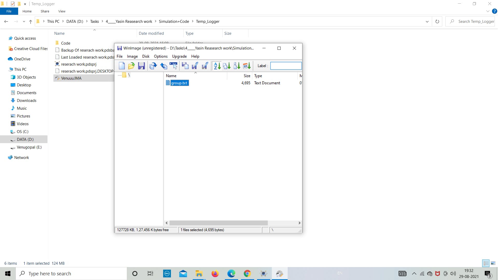
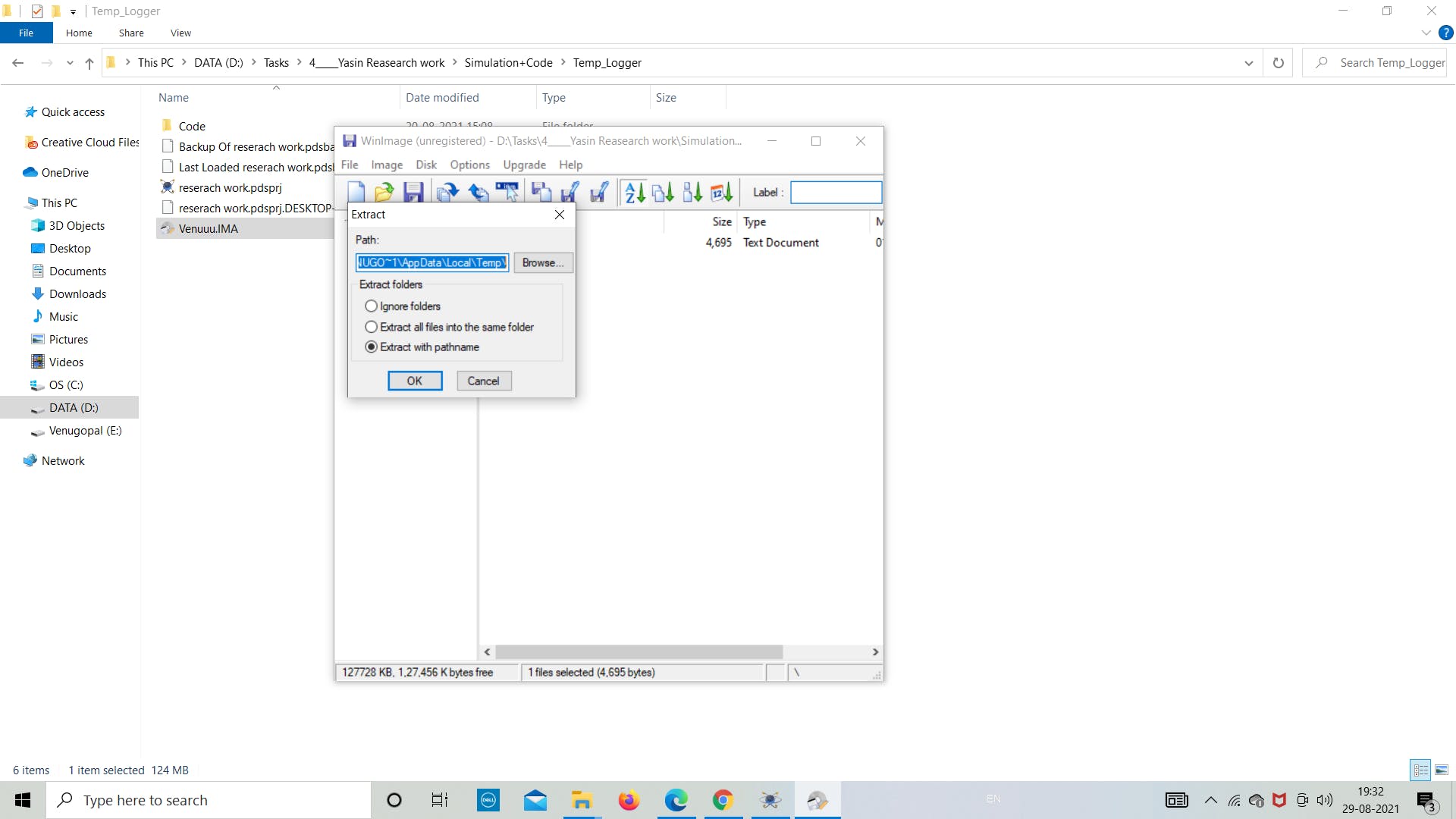
让我们打开“Venuuu.IMG”文件来查看图像文件中的内容。
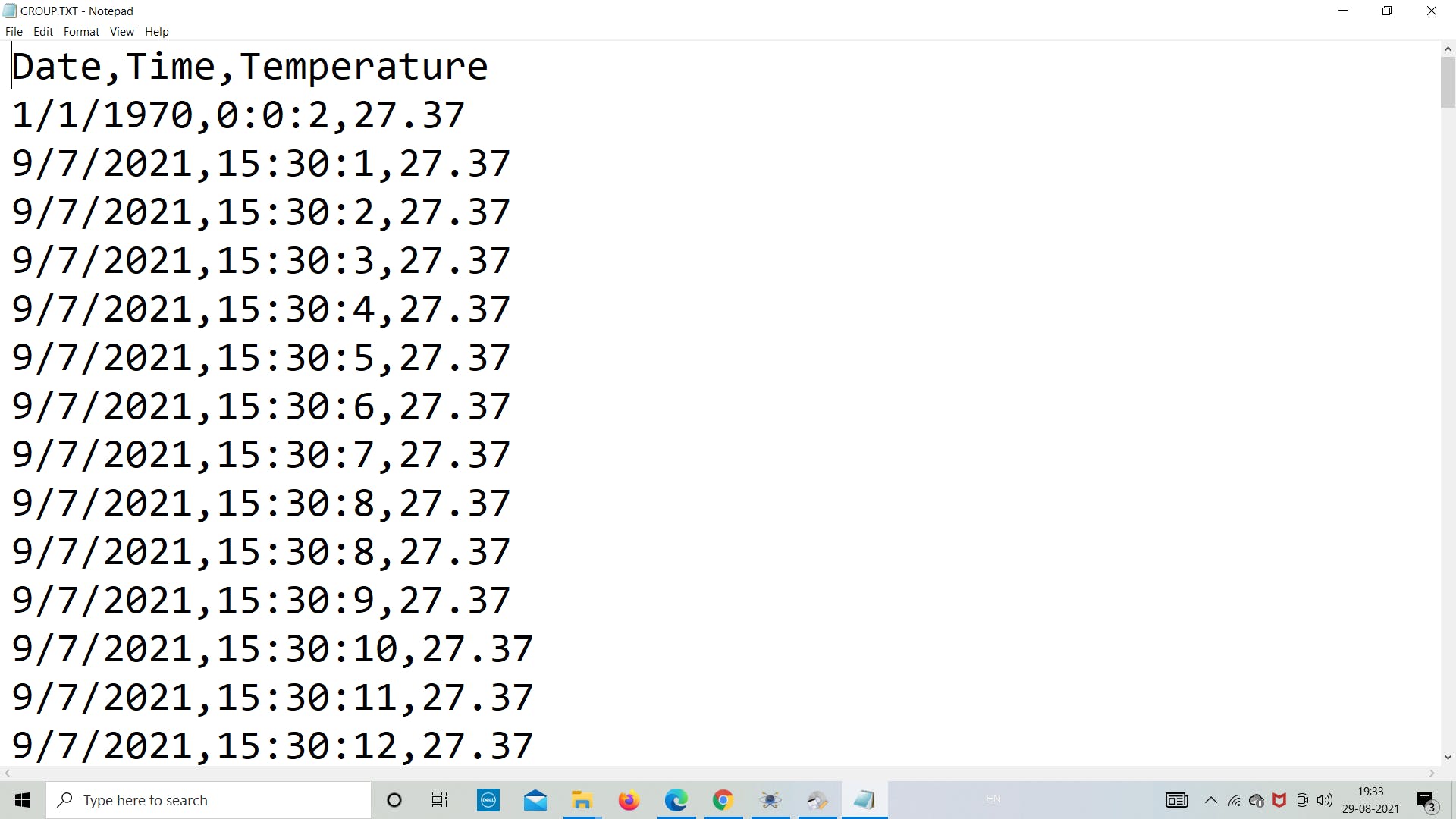
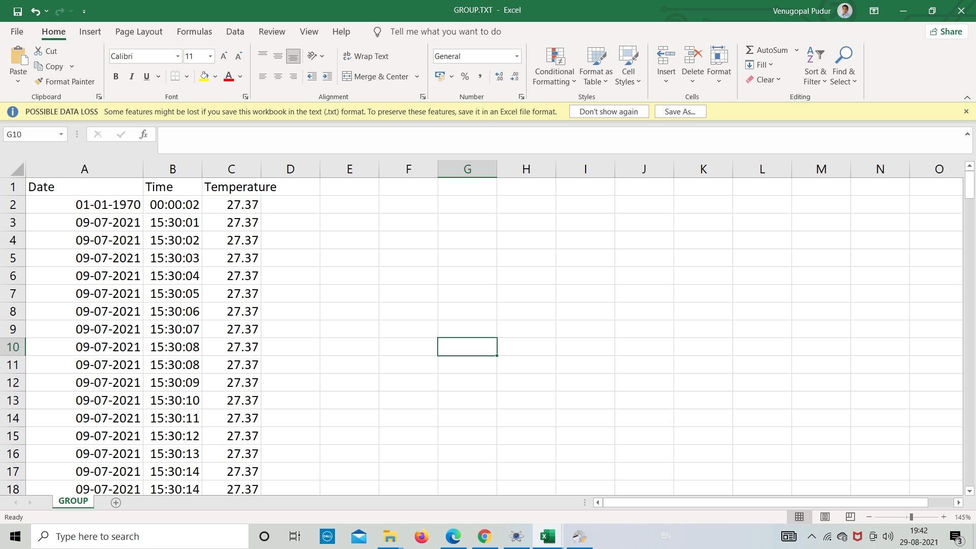
如下图所示,我们可以看到在图像文件中创建了名为“group.txt”的.txt文件。现在我们将通过双击它来导出文件。然后它会自动打开文件,我们可以看到里面存储的温度数据。
按照下图重新创建实验。
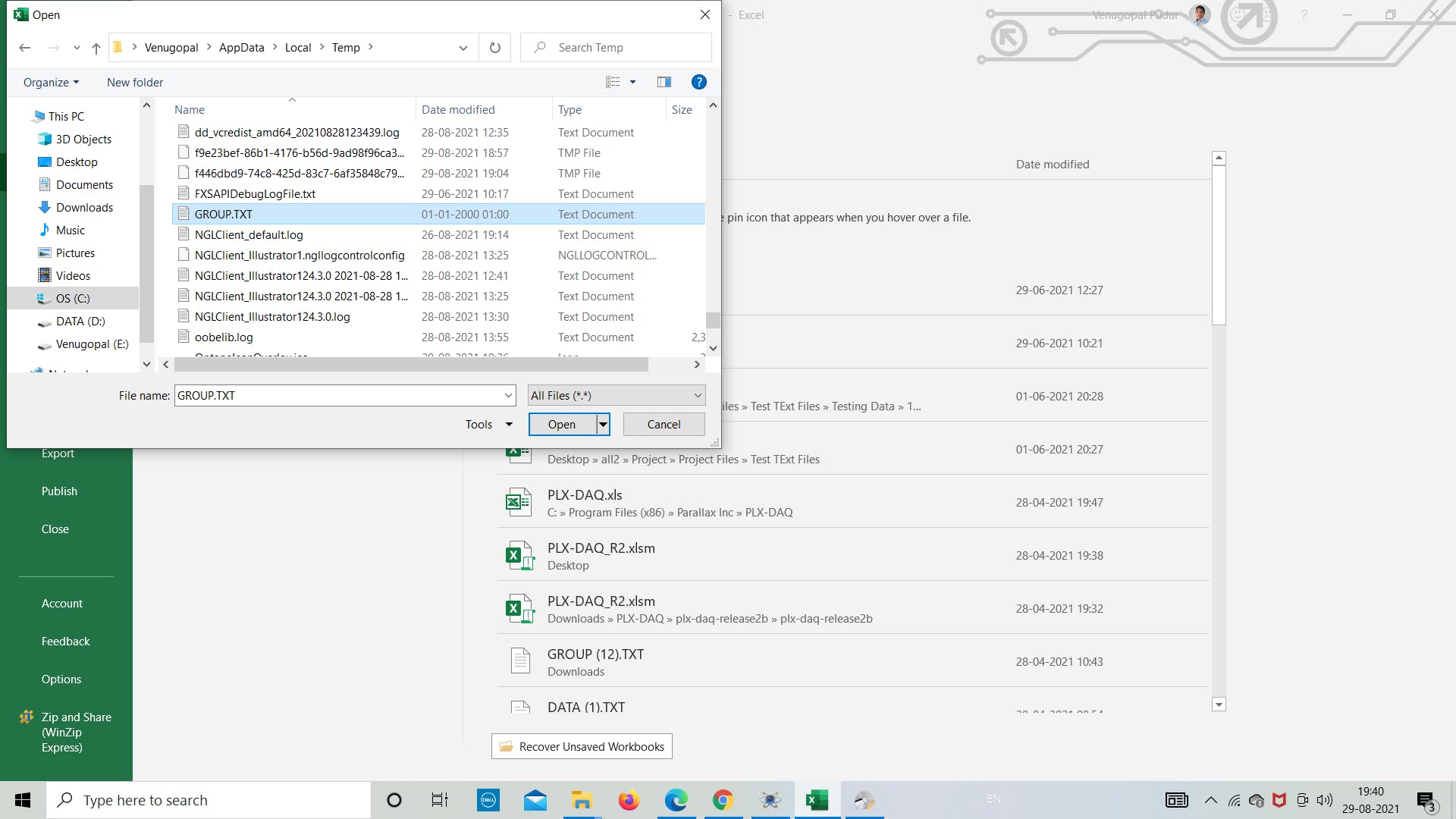
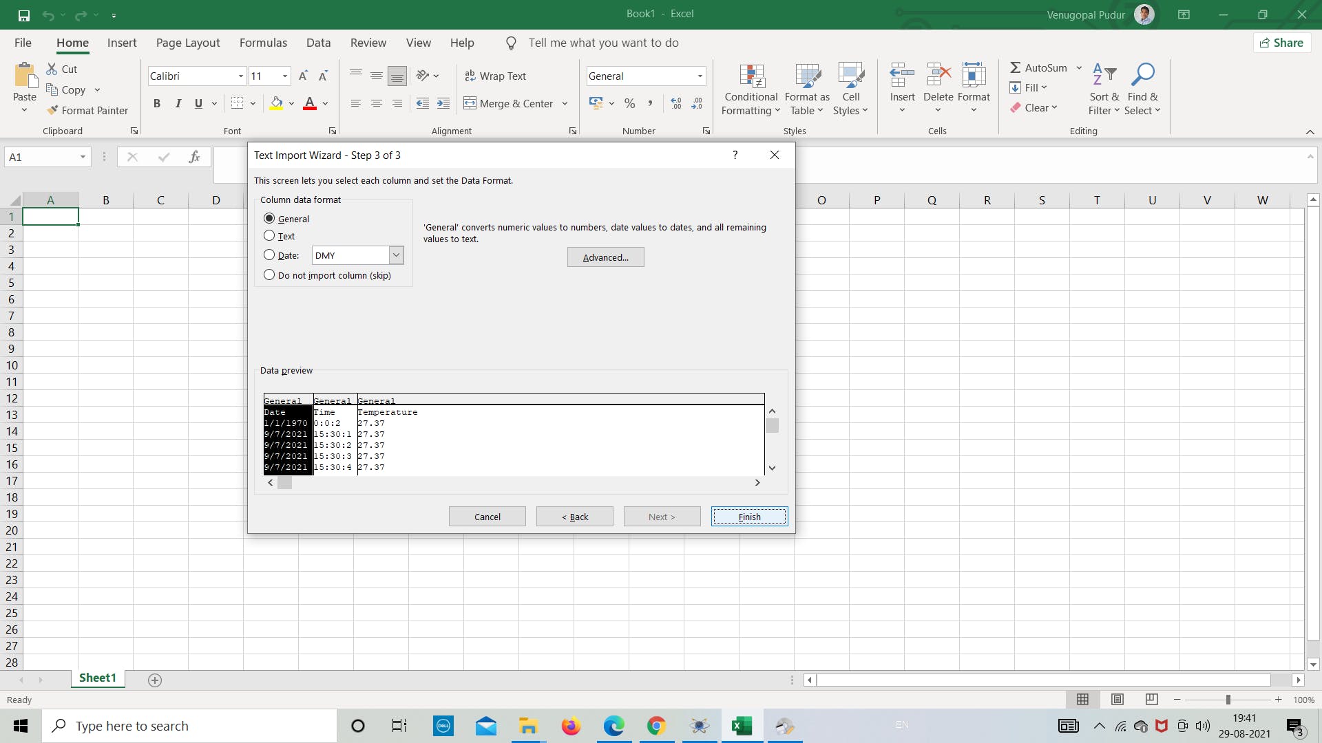
现在我们打开 excel 将文件转换为 excel 格式,以便根据数据或任何其他我们想要的目的绘制图形。
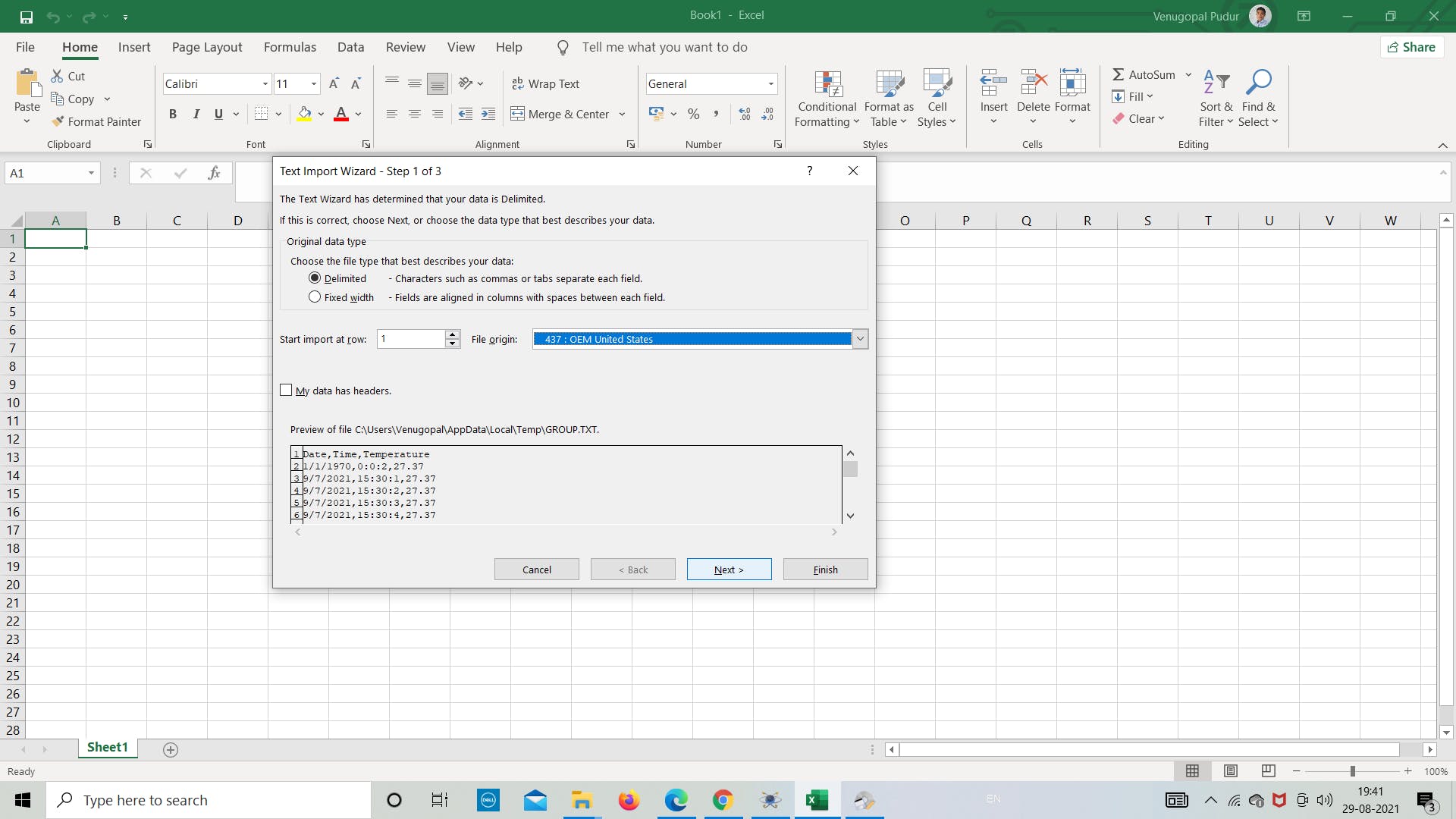
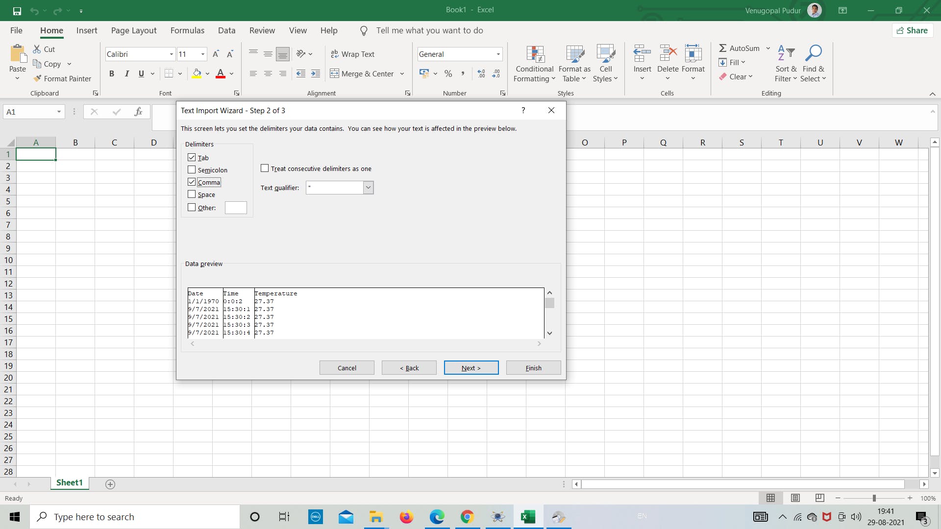
打开 .txt 文件并将分隔符设置为用逗号分隔以将数据分隔为列,然后根据需要继续分析数据。
这都是关于使用 SD 卡模块在 Proteus 中进行的简单模拟。
感谢您阅读本文,祝您有美好的一天!
声明:本文内容及配图由入驻作者撰写或者入驻合作网站授权转载。文章观点仅代表作者本人,不代表电子发烧友网立场。文章及其配图仅供工程师学习之用,如有内容侵权或者其他违规问题,请联系本站处理。 举报投诉
- 相关下载
- 相关文章


