
资料下载


量化桌面物联网项目
YYXIAO
分享资料个
描述
作为一个量化的自我爱好者,我想跟踪我在站立式办公桌上坐着和站着的时间,并在图表中很好地可视化。
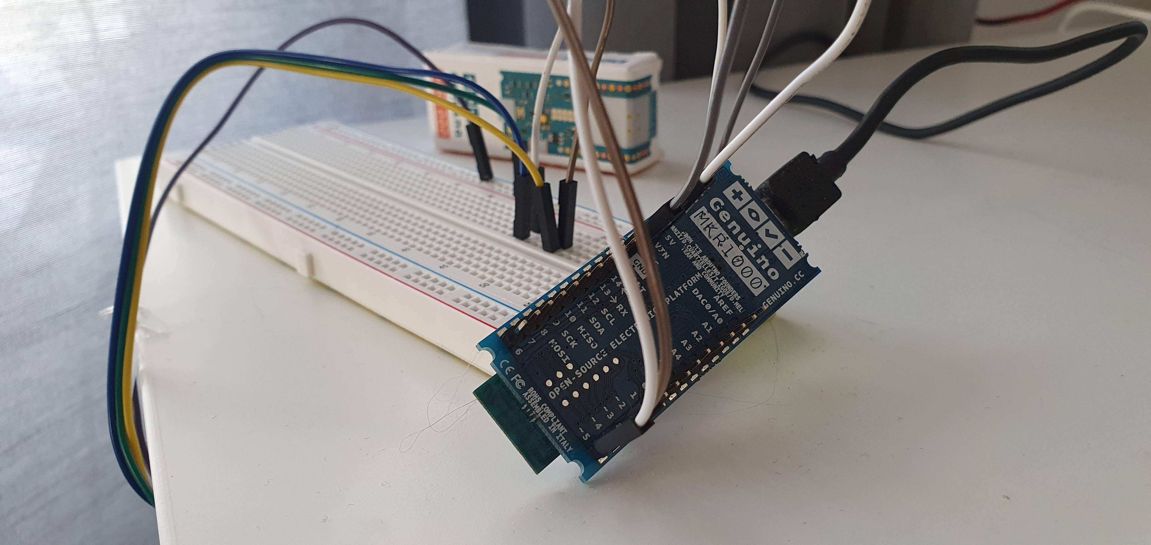
我也一直想使用 Microsoft Azure 开展个人物联网项目,因此我将我的 Genuino MKR1000 掸掉,将其连接到超声波传感器并提出了这个项目。
这个概念很简单:
- 使用超声波传感器通过将桌子放在桌面下方来测量桌子的高度并计算到地板的距离
- 定期将该数据发送到 Azure IoT 中心,并将其路由到队列服务(Azure 服务总线队列)
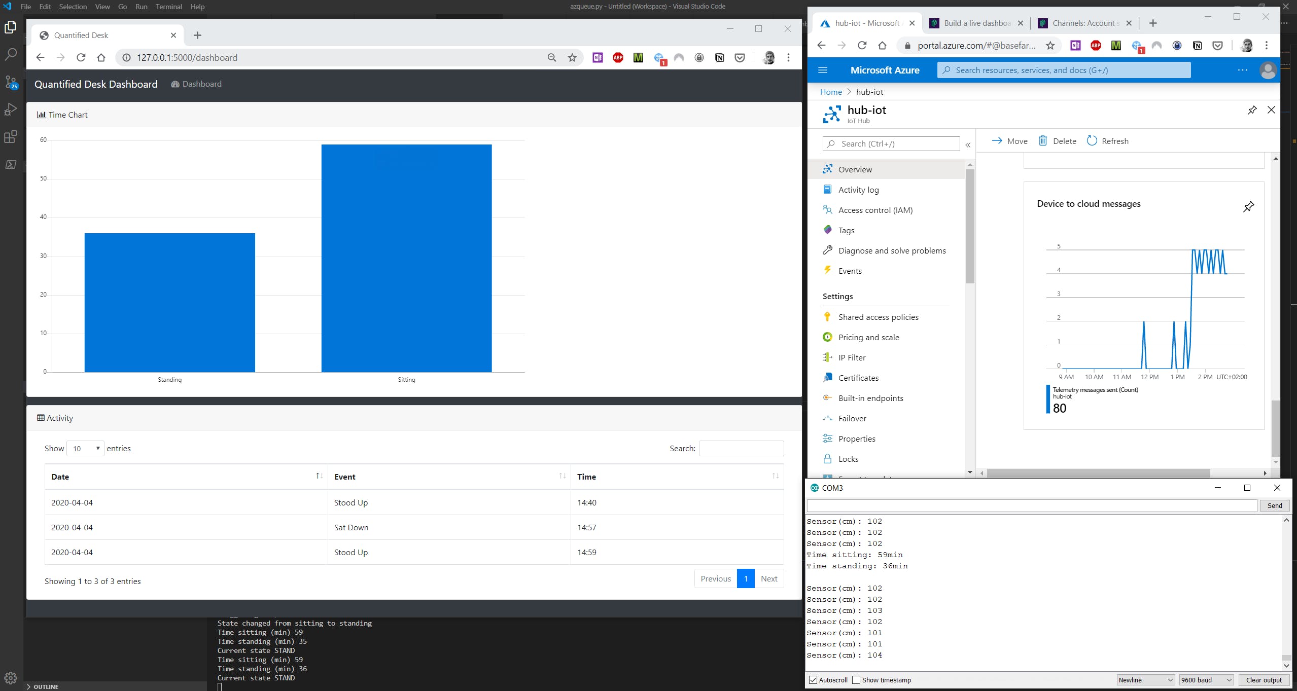
- 使用 Python 应用程序使用数据来构建实时仪表板
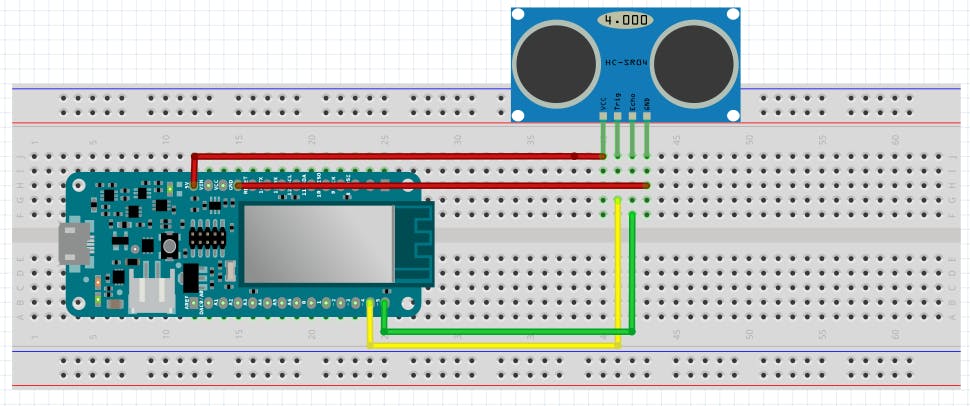
接线非常简单:
设置:
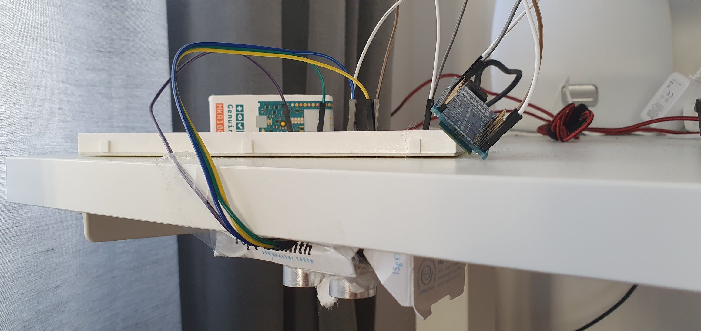
您只需确保将传感器放置在桌子上与地板之间没有障碍物的位置(例如:地板上的任何物体、椅子或您坐着时的腿)。所以把它放在一个角落里。
为了避免计算中的“噪音”(即您的腿或手臂可能在传感器下方的短暂时刻,或者由于测量高度较低而暂时阻碍程序认为您处于坐姿的任何东西),进行了测量每 5 秒一次,并且仅使用最后 12 次测量的平均值来确定当前位置并计算坐/站时间,然后将该数据发送到 azure(12 * 5 = 60 秒,因此每分钟)。
这是 Arduino 代码(或从此链接获取):
/*******************************************************************
This code implements the Quantified Desk project, which consists of
an Arduino/Genuino MKR1000 hooked up to an ultrasonic sensor to measure
the distance to the floor (height) of a standing desk.
It keeps track of the time duration (in minutes) in each state (Sitting/Standing)
which is defined by a distance threshold above which the desk is considered to be
in standing position, and below which it is considered in sitting position.
A time counter for each state increases if the corresponding state is the current state.
This data is periodically sent to Azure IoT Hub along with a timestamp.
Complete Project with Dashboard visualization
https://github.com/vmehmeri/az-iot/QuantifiedDesk
PRE-REQUISITE
Setup Azure IoT Hub and upload SSL certificate to device (for your
IoT Hub hostname). With older firmware versions the HTTP Post function
will be unreliable and may fail on several requests, so it's recommended
to update your MKR1000 firmware to the latest version.
- Instructions for setting up Azure IoT Hub:
https://docs.microsoft.com/en-us/azure/iot-hub/iot-hub-create-through-portal
- Instructions for updating Firmware and adding SSL certificate to device:
https://www.arduino.cc/en/Tutorial/FirmwareUpdater
*******************************************************************/
#include
#include
#include
#include
#include "arduino_secrets.h"
// SECRETS CONFIG -- PLEASE SET THESE IN arduino_secrets.h FILE
//WiFi creds -------------------------------------------------------------------------------------------
char ssid[] = SECRET_SSID; //  your network SSID (name)
char pass[] = SECRET_WIFIPASSWD;    // your network password (use for WPA, or use as key for WEP)
//Azure IoT Hub Secrets Config -------------------------------------------------------------------------
char hostname[] = SECRET_IOTHUB_HOSTNAME;
char uri[]= SECRET_DEVICE_POST_URI;
char authSAS[] = SECRET_DEVICE_SAS;
//------------------------------------------------------------------------------------------------------
#define slotNumber 1 //This will vary for multi slot devices
// Project Config variables
unsigned int distanceThreshold = 82; // Define here the distance (in cm) that marks the threshold between sitting and standing
const int GMT = 2; //change this to adapt it to your time zone
const int TrigPin = 4; //number of the Trigger pin
const int EchoPin = 5; //number of the Echo pin
RTCZero rtc;
WiFiSSLClient client;
Ultrasonic ultrasonic(TrigPin, EchoPin);
unsigned int count = 0;
unsigned long distanceSum = 0;
unsigned int timeStanding = 0;
unsigned int timeSitting = 0;
unsigned long startMillis;
unsigned long distanceAvg;
unsigned long distance;
int status = WL_IDLE_STATUS;
void setup() {
Serial.begin(9600);
while (!Serial) {
; // wait for serial port to connect. Needed for native USB port only
}
startMillis = millis();
rtc.begin();
// check for the presence of the shield:
if (WiFi.status() == WL_NO_SHIELD) {
Serial.println("WiFi shield not present");
// don't continue:
while (true);
}
// attempt to connect to Wifi network:
while ( status != WL_CONNECTED) {
Serial.print("Attempting to connect to SSID: ");
Serial.println(ssid);
status = WiFi.begin(ssid, pass);
// wait 10 seconds for connection:
delay(10000);
}
Serial.println("Connected to Wi-Fi");
// Get Real-Time from NTP using built-in RTC module
unsigned long epoch;
int numberOfTries = 0, maxTries = 6;
do {
epoch = WiFi.getTime();
numberOfTries++;
}
while ((epoch == 0) && (numberOfTries < maxTries));
if (numberOfTries == maxTries) {
Serial.print("NTP unreachable!!");
while (1);
}
else {
Serial.print("Epoch received: ");
Serial.println(epoch);
rtc.setEpoch(epoch);
Serial.println();
}
}
void loop() {
delay(5000); // wait 5 seconds
ultrasonic.measure();
distance = ultrasonic.get_cm();
Serial.print("Sensor(cm): ");
Serial.println(distance);
distanceSum = distanceSum + distance;
count = count + 1;
/* Takes the average of the last 12 measurements (the number 12 is arbitrary, but
*  with a 5-second delay between measurements and 12 measurements, that means
*  data is aggregated and sent to Azure every 60 seconds, which seems reasonable for
*  this project.
*/
if (count == 12) {
distanceAvg = distanceSum / count;
count = 0;
distanceSum = 0;
if (distanceAvg < distanceThreshold) {
// Add elapsed time since last measurement to sitting time
timeSitting = timeSitting + ((millis()-startMillis)/1000);
} else {
// Add elapsed time since last measurement to standing time
timeStanding = timeStanding + ((millis()-startMillis)/1000);
}
startMillis = millis();
// Show current aggregate numbers
printRTCDate();
printRTCTime();
Serial.println();
Serial.print("Time sitting: ");
Serial.print(timeSitting/60);
Serial.println("min");
Serial.print("Time standing: ");
Serial.print(timeStanding/60);
Serial.println("min");
Serial.println("");
// Creates a string to send to Azure IoT HUB.
// It's simply comma-separated string of values for sitting and standing, followed by date and time (for timestamping)
String data_string = (String(timeSitting/60) + "," + String(timeStanding/60) + "," + getRTCDate() + "," + getRTCTime());
//Serial.println(data_string);
// Send to Azure
httpPost(data_string);
String response = "";
char c;
while (client.available()) {
c = client.read();
response.concat(c);
}
}
}
void httpPost(String content)
{
if (client.connectSSL(hostname, 443)) {
client.print("POST ");
client.print(uri);
client.println(" HTTP/1.1");
client.print("Host: ");
client.println(hostname);
client.print("Authorization: ");
client.println(authSAS);
client.println("Connection: close");
client.print("Content-Type: ");
client.println("text/plain");
client.print("Content-Length: ");
client.println(content.length());
client.println();
client.println(content);
delay(500);
} else {
Serial.println("HTTP POST connection failed");
Serial.println(client.read());
}
// close connection
client.stop();
}
void printRTCTime()
{
print2digits(rtc.getHours() + GMT);
Serial.print(":");
print2digits(rtc.getMinutes());
Serial.print(":");
print2digits(rtc.getSeconds());
Serial.println();
}
void printRTCDate()
{
Serial.print(rtc.getDay());
Serial.print("/");
Serial.print(rtc.getMonth());
Serial.print("/");
Serial.print(rtc.getYear());
Serial.print(" ");
}
void print2digits(int number) {
if (number < 10) {
Serial.print("0");
}
Serial.print(number);
}
String getRTCDate()
{
String date_str = String(rtc.getDay()) + "/" + String(rtc.getMonth()) + "/" + String(rtc.getYear());
return date_str;
}
String getRTCTime()
{
String time_str = get2digits(rtc.getHours() + GMT) + ":" + get2digits(rtc.getMinutes()) + ":" + get2digits(rtc.getSeconds());
return time_str;
}
String get2digits(int number) {
if (number < 10) {
return "0" + String(number);
}
return String(number);
}
请注意,必须提供 Azure 连接详细信息,因此您需要先设置 Azure IoT 中心。
以下是设置 Azure IoT 中心的说明:
https://docs.microsoft.com/en-us/azure/iot-hub/iot-hub-create-through-portal
免费层就可以满足这一需求。所以它不会花费你任何东西!
仪表板
对于实时仪表板,我使用了 Pusher (pusher.com)。我按照本教程修改了我的应用程序的示例代码。
您可以使用我的代码(如下提供)作为参考,但您需要创建一个帐户,创建一个应用程序,并记下您的应用程序连接密钥,如下所示:
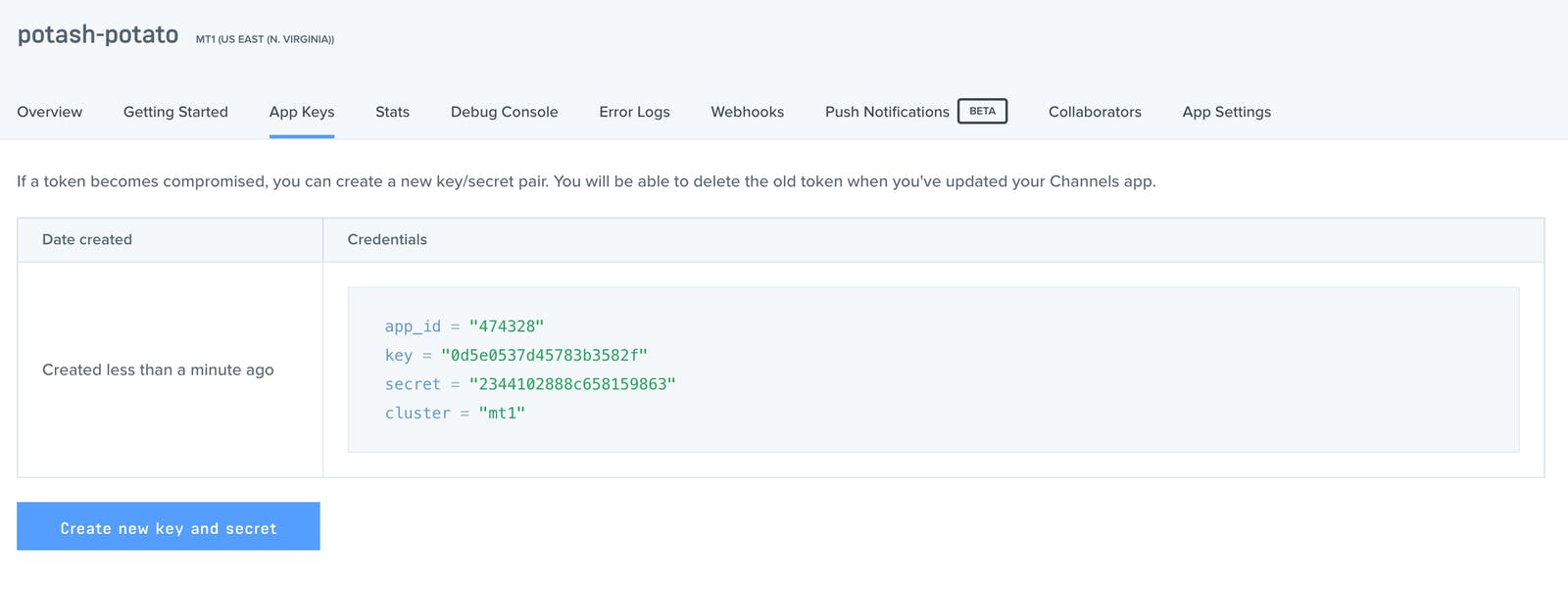
别担心,这应该花费您不到 5 分钟的时间来完成设置。
完成后,下载我的 Github 存储库中可用的代码:
https://github.com/vmehmeri/az-iot/tree/master/QuantifiedDesk
修改以下文件:
frontend/app.py
device_handler.py
使用您的应用程序密钥(对于设备处理程序,还有您的 Azure 连接信息)。您会注意到需要有关 Azure 服务总线队列的信息。在我的应用程序中,我让 Azure IoT 中心将消息路由到服务总线队列,然后从那里使用它们。设置 Azure 服务总线队列非常简单,您可以按照本教程进行操作:
在“消息传递”>“消息传递路由”>“添加”下配置 IoT 中心消息路由(然后选择您的队列)
之后,您就可以运行该应用程序了。首先,运行前端:
python frontend/app.py
在另一个终端中,运行设备处理程序,即后端应用程序:
python device_handler.py
现在,您可以在localhost:5000上打开一个浏览器窗口,然后盯着图表,同时看到条形的增长取决于您站在或坐在办公桌前的时间长短 :)(可能需要 1-2 分钟才能看到任何变化在仪表板中)
您还可以打开 Arduino 串行监视器以获得更直接和详细的输出。device_handler 的 python 代码在从设备获取消息时也应该输出一些文本。
声明:本文内容及配图由入驻作者撰写或者入驻合作网站授权转载。文章观点仅代表作者本人,不代表电子发烧友网立场。文章及其配图仅供工程师学习之用,如有内容侵权或者其他违规问题,请联系本站处理。 举报投诉
- 相关下载
- 相关文章


